2006 NISSAN PATROL fuel type
[x] Cancel search: fuel typePage 166 of 1226
Fuel Injection System
SYSTEM DESCRIPTION
Three types of fuel injection control are provided to accommodate engine operating conditions; normal control,
idle control and start control. The ECM determines the appropriate fuel injection control. Under each control,
the amount of fuel injected is compensated to improve engine performance. The ECM performs duty control
on the electric governor (built into the fuel injection pump) according to sensor signals to compensate the
amount of fuel injected to the preset value.
START CONTROL
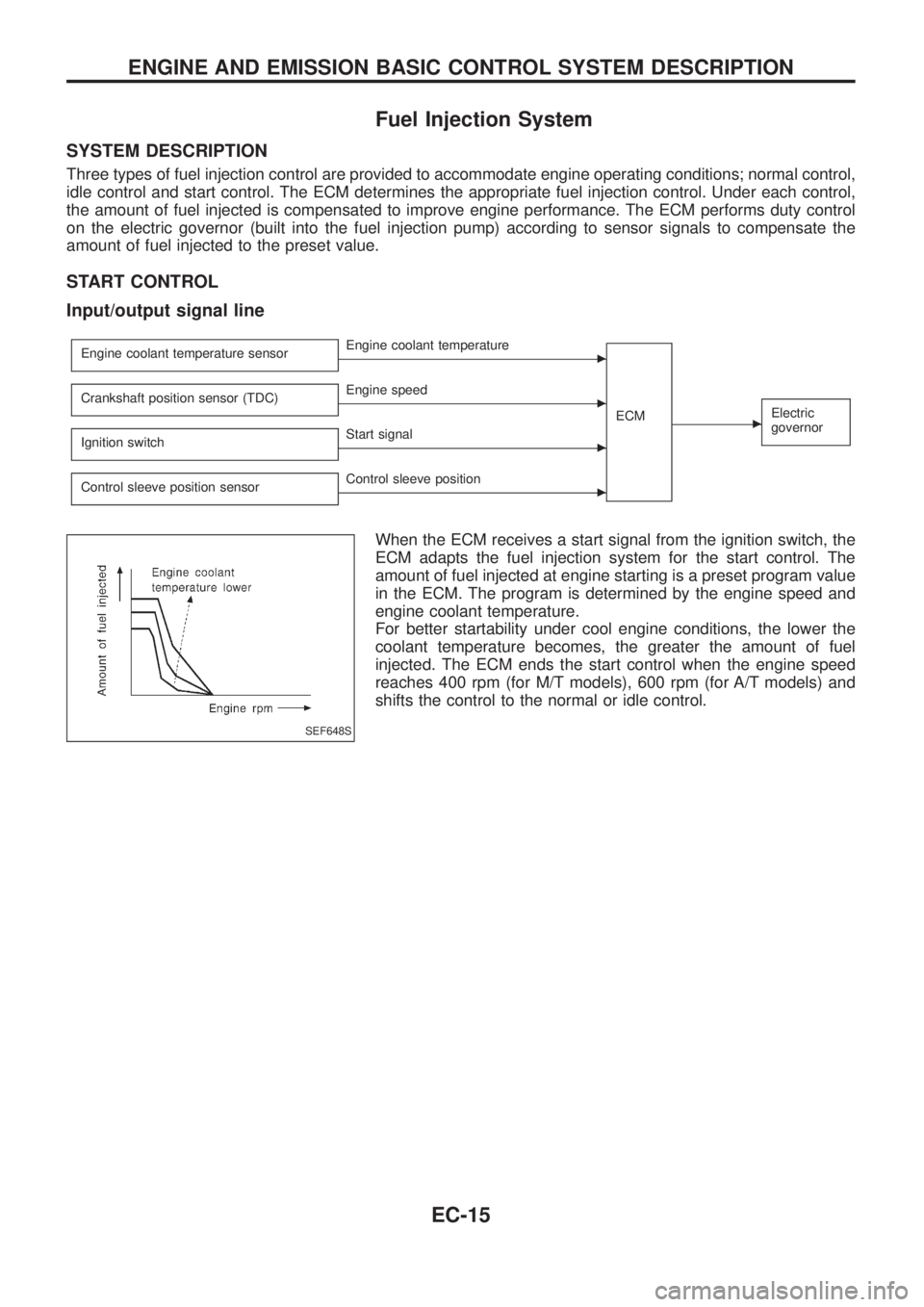
Input/output signal line
Engine coolant temperature sensorcEngine coolant temperature
ECM
cElectric
governorCrankshaft position sensor (TDC)cEngine speed
Ignition switch
cStart signal
Control sleeve position sensor
cControl sleeve position
When the ECM receives a start signal from the ignition switch, the
ECM adapts the fuel injection system for the start control. The
amount of fuel injected at engine starting is a preset program value
in the ECM. The program is determined by the engine speed and
engine coolant temperature.
For better startability under cool engine conditions, the lower the
coolant temperature becomes, the greater the amount of fuel
injected. The ECM ends the start control when the engine speed
reaches 400 rpm (for M/T models), 600 rpm (for A/T models) and
shifts the control to the normal or idle control.
SEF648S
ENGINE AND EMISSION BASIC CONTROL SYSTEM DESCRIPTION
EC-15
Page 408 of 1226
Bulb Replacement
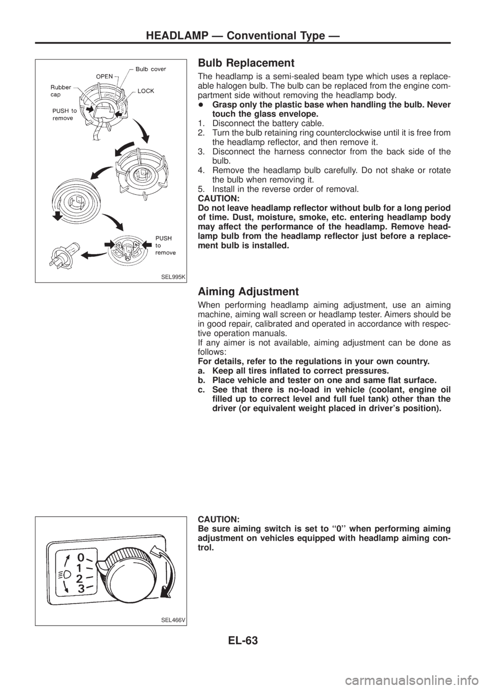
The headlamp is a semi-sealed beam type which uses a replace-
able halogen bulb. The bulb can be replaced from the engine com-
partment side without removing the headlamp body.
+Grasp only the plastic base when handling the bulb. Never
touch the glass envelope.
1. Disconnect the battery cable.
2. Turn the bulb retaining ring counterclockwise until it is free from
the headlamp re¯ector, and then remove it.
3. Disconnect the harness connector from the back side of the
bulb.
4. Remove the headlamp bulb carefully. Do not shake or rotate
the bulb when removing it.
5. Install in the reverse order of removal.
CAUTION:
Do not leave headlamp re¯ector without bulb for a long period
of time. Dust, moisture, smoke, etc. entering headlamp body
may affect the performance of the headlamp. Remove head-
lamp bulb from the headlamp re¯ector just before a replace-
ment bulb is installed.
Aiming Adjustment
When performing headlamp aiming adjustment, use an aiming
machine, aiming wall screen or headlamp tester. Aimers should be
in good repair, calibrated and operated in accordance with respec-
tive operation manuals.
If any aimer is not available, aiming adjustment can be done as
follows:
For details, refer to the regulations in your own country.
a. Keep all tires in¯ated to correct pressures.
b. Place vehicle and tester on one and same ¯at surface.
c. See that there is no-load in vehicle (coolant, engine oil
®lled up to correct level and full fuel tank) other than the
driver (or equivalent weight placed in driver's position).
CAUTION:
Be sure aiming switch is set to ``0'' when performing aiming
adjustment on vehicles equipped with headlamp aiming con-
trol.
SEL995K
SEL466V
HEADLAMP Ð Conventional Type Ð
EL-63
Page 479 of 1226
Electrical Components Inspection
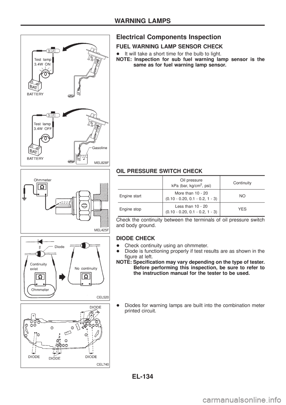
FUEL WARNING LAMP SENSOR CHECK
+It will take a short time for the bulb to light.
NOTE: Inspection for sub fuel warning lamp sensor is the
same as for fuel warning lamp sensor.
OIL PRESSURE SWITCH CHECK
Oil pressure
kPa (bar, kg/cm2, psi)Continuity
Engine startMore than 10 - 20
(0.10 - 0.20, 0.1 - 0.2,1-3)NO
Engine stopLess than 10 - 20
(0.10 - 0.20, 0.1 - 0.2,1-3)YES
Check the continuity between the terminals of oil pressure switch
and body ground.
DIODE CHECK
+Check continuity using an ohmmeter.
+Diode is functioning properly if test results are as shown in the
®gure at left.
NOTE: Speci®cation may vary depending on the type of tester.
Before performing this inspection, be sure to refer to
the instruction manual for the tester to be used.
+Diodes for warning lamps are built into the combination meter
printed circuit.
MEL828F
MEL425F
CEL520
CEL740
WARNING LAMPS
EL-134
Page 760 of 1226
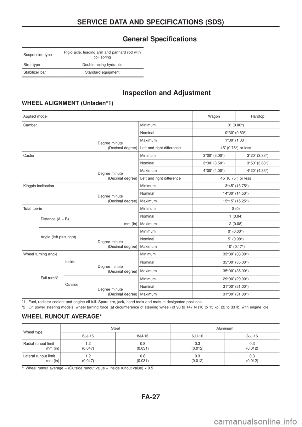
General Speci®cations
Suspension typeRigid axle, leading arm and panhard rod with
coil spring
Strut type Double-acting hydraulic
Stabilizer bar Standard equipment
Inspection and Adjustment
WHEEL ALIGNMENT (Unladen*1)
Applied modelWagon Hardtop
Camber Minimum 0É (0.00É)
Degree minute
(Decimal degree)Nominal 0É30¢(0.50É)
Maximum 1É00¢(1.00É)
Left and right difference 45¢(0.75É) or less
Caster Minimum 3É00¢(3.00É) 3É20¢(3.33É)
Degree minute
(Decimal degree)Nominal 3É30¢(3.50É) 3É50¢(3.83É)
Maximum 4É00¢(4.00É) 4É20¢(4.33É)
Left and right difference 45¢(0.75É) or less
Kingpin inclination Minimum 13É45¢(13.75É)
Degree minute
(Decimal degree)Nominal 14É30¢(14.50É)
Maximum 15É15¢(15.25É)
Total toe-in Minimum 0 (0)
Distance (A þ B)
mm (in)Nominal 1 (0.04)
Maximum 2 (0.08)
Angle (left plus right)
Degree minute
(Decimal degree)Minimum 0¢(0.00É)
Nominal 5¢(0.08É)
Maximum 10¢(0.17É)
Wheel turning angle Minimum 33É00¢(33.00É)
Full turn*2Inside
Degree minute
(Decimal degree)Nominal 35É00¢(35.00É)
Maximum 35É00¢(35.00É)
Outside
Degree minute
(Decimal degree)Minimum 29É00¢(29.00É)
Nominal 31É00¢(31.00É)
Maximum 31É00¢(31.00É)
*1: Fuel, radiator coolant and engine oil full. Spare tire, jack, hand tools and mats in designated positions.
*2: On power steering models, wheel turning force (at circumference of steering wheel) of 98 to 147 N (10 to 15 kg, 22 to 33 lb) with engine idle.
WHEEL RUNOUT AVERAGE*
Wheel typeSteel Aluminum
6JJ-16 8JJ-16 6JJ-16 8JJ-16
Radial runout limit
mm (in)1.2
(0.047)0.8
(0.031)0.3
(0.012)0.3
(0.012)
Lateral runout limit
mm (in)1.2
(0.047)0.8
(0.031)0.3
(0.012)0.3
(0.012)
*: Wheel runout average = (Outside runout value + Inside runout value) x 0.5
SERVICE DATA AND SPECIFICATIONS (SDS)
FA-27
Page 778 of 1226
Dispose of used oil and used oil ®lters through authorized waste
disposal contractors to licensed waste disposal sites, or to the
waste oil reclamation trade. If in doubt, contact the local authority
for advice on disposal facilities.
It is illegal to pour used oil on to the ground, down sewers or drains,
or into water courses.
The regulations concerning the pollution of the environment
will vary from country to country.
Precautions for Fuel
GASOLINE ENGINE:
Three way catalyst equipped models ... unleaded gasoline of at
least 91 octane (RON)
CAUTION:
Do not use leaded gasoline. Using leaded gasoline will dam-
age the three way catalyst.
Except for the above models ... unleaded or leaded gasoline of
above 88 octane (RON)
Use unleaded fuel if instructed on the fuel ®ller lid.
DIESEL ENGINE*:
Diesel fuel of above 45 cetane for TD42 engine and above 50 cet-
ane for RD28ET engine
* If two types of diesel fuel are available, use summer or winter
fuel properly according to the following temperature conditions.
+Above þ7ÉC (20ÉF) ... Summer type diesel fuel.
+Below þ7ÉC (20ÉF) ... Winter type diesel fuel.
CAUTION:
+Do not use home heating oil, gasoline, or other alternate
fuels in your diesel engine. The use of those can cause
engine damage.
+Do not use summer fuel at temperature below þ7ÉC (20ÉF).
The cold temperature will cause wax to form in the fuel. As
a result, it may prevent the engine from running smoothly.
+Do not add gasoline or other alternate fuels to diesel fuel.
Precautions for Air Conditioning
Use an approved refrigerant recovery unit any time the air condi-
tioning system must be discharged. Refer to HA section (``HFC-
134a (R-134a) Service Procedure'', ``SERVICE PROCEDURES'')
for speci®c instructions.
PRECAUTIONS
Precautions for Engine Oils (Cont'd)
GI-5
Page 982 of 1226
![NISSAN PATROL 2006 Service Manual Engine and Emission Control Service
Annual driving distance below 30,000 km (18,000 miles)
Abbreviations: I = Inspect and correct or replace as necessary, R = Replace, A = Adjust. [ ]: At the speci®e NISSAN PATROL 2006 Service Manual Engine and Emission Control Service
Annual driving distance below 30,000 km (18,000 miles)
Abbreviations: I = Inspect and correct or replace as necessary, R = Replace, A = Adjust. [ ]: At the speci®e](/manual-img/5/57368/w960_57368-981.png)
Engine and Emission Control Service
Annual driving distance below 30,000 km (18,000 miles)
Abbreviations: I = Inspect and correct or replace as necessary, R = Replace, A = Adjust. [ ]: At the speci®ed mileage only
MAINTENANCE OPERATIONMAINTENANCE INTERVAL
Reference
page Perform either at number of kilometers (miles)
or months, whichever comes ®rst.km x 1,000 10 20 30 40 50 60 70 80 90
(Miles x 1,000) (6) (12) (18) (24) (30) (36) (42) (48) (54)
Months 6 12 18 24 30 36 42 48 54
Underhood and under vehicle
Engine anti-freeze coolant (Ethylene glycol base, LLC) See NOTE (2) R MA-14
Cooling systemI I I MA-16
Fuel linesI I MA-17
Fuel ®lterR R MA-16
Air cleaner ®lter (Viscous paper type).R R MA-18
Intake & exhaust valve clearanceAAAA *1
Injection nozzles See NOTE (3)MA-18
Timing belts for camshaft and injection pump[R] *2
NOTE: (1) Maintenance items with ``.'' should be performed more frequently according to ``Maintenance Under Severe
Driving Conditions''.
(2) First replace at 80,000 km (48,000 miles) or 48 months, then every 60,000 km (36,000 miles) or 36 months.
(3) If engine power decreases, black smoke is emitted or engine noise increases, check and, if necessary, adjust
the fuel injection nozzle's starting pressure and the fuel spray pattern.
*1: ``VALVE CLEARANCE'', RD in EM section
*2: ``TIMING BELT'' RD in EM section
Annual driving distance over 30,000 km (18,000 miles)
Abbreviations: I = Inspect and correct or replace as necessary, R = Replace, A = Adjust.
MAINTENANCE OPERATIONMAINTENANCE INTERVAL
Reference
page km x 1,000 10 20 30 40 50 60 70 80 90
(Miles x 1,000) (6) (12) (18) (24) (30) (36) (42) (48) (54)
Underhood and under vehicle
Engine anti-freeze coolant (Ethylene glycol base, LLC) See NOTE (2) R MA-14
Cooling systemI I MA-16
Fuel linesI MA-17
Fuel ®lterR MA-16
Air cleaner ®lter (Viscous paper type).R MA-18
Intake & exhaust valve clearanceAAA*1
Injection nozzles See NOTE (3)MA-18
Timing belts for camshaft and injection pumpR*2
NOTE: (1) Maintenance items with ``.'' should be performed more frequently according to ``Maintenance Under Severe
Driving Conditions''.
(2) First replace at 90,000 km (54,000 miles), then every 60,000 km (36,000 miles).
(3) If engine power decreases, black smoke is emitted or engine noise increases, check and, if necessary, adjust
the fuel injection nozzle's starting pressure and the fuel spray pattern.
*1: ``VALVE CLEARANCE'', RD in EM section
*2: ``TIMING BELT'', RD in EM section
PERIODIC MAINTENANCE
MA-5
Page 985 of 1226
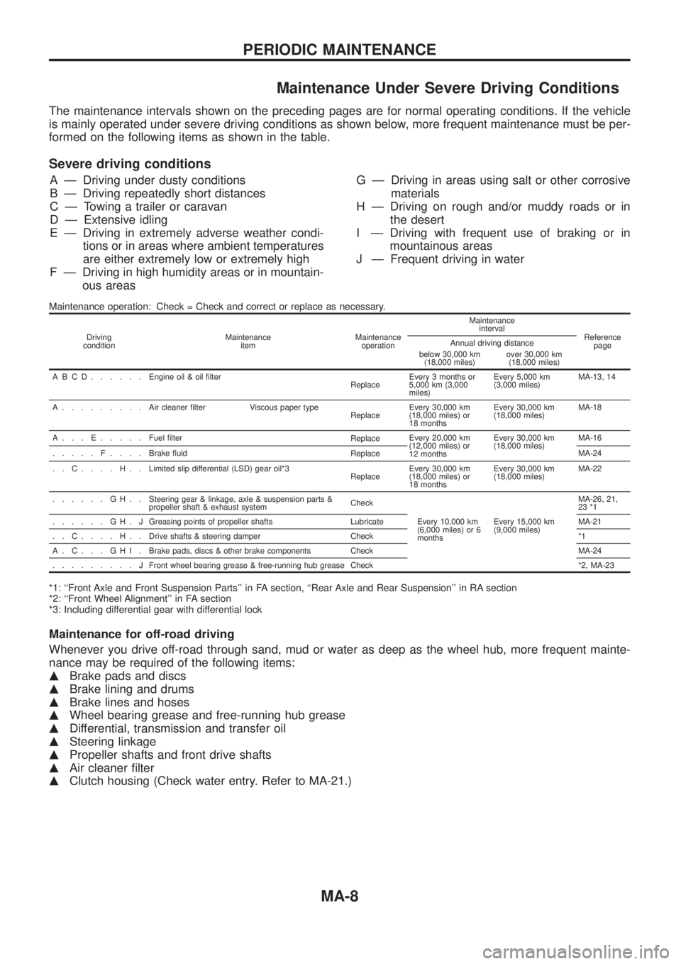
Maintenance Under Severe Driving Conditions
The maintenance intervals shown on the preceding pages are for normal operating conditions. If the vehicle
is mainly operated under severe driving conditions as shown below, more frequent maintenance must be per-
formed on the following items as shown in the table.
Severe driving conditions
A Ð Driving under dusty conditions
B Ð Driving repeatedly short distances
C Ð Towing a trailer or caravan
D Ð Extensive idling
E Ð Driving in extremely adverse weather condi-
tions or in areas where ambient temperatures
are either extremely low or extremely high
F Ð Driving in high humidity areas or in mountain-
ous areasG Ð Driving in areas using salt or other corrosive
materials
H Ð Driving on rough and/or muddy roads or in
the desert
I Ð Driving with frequent use of braking or in
mountainous areas
J Ð Frequent driving in water
Maintenance operation: Check = Check and correct or replace as necessary.
Driving
conditionMaintenance
itemMaintenance
operationMaintenance
interval
Reference
page Annual driving distance
below 30,000 km
(18,000 miles)over 30,000 km
(18,000 miles)
ABCD......Engine oil & oil ®lter
ReplaceEvery 3 months or
5,000 km (3,000
miles)Every 5,000 km
(3,000 miles)MA-13, 14
A.........Aircleaner ®lter Viscous paper type
ReplaceEvery 30,000 km
(18,000 miles) or
18 monthsEvery 30,000 km
(18,000 miles)MA-18
A...E.....Fuel ®lter
ReplaceEvery 20,000 km
(12,000 miles) or
12 monthsEvery 30,000 km
(18,000 miles)MA-16
.....F....Brake ¯uid
ReplaceMA-24
..C....H..Limited slip differential (LSD) gear oil*3
ReplaceEvery 30,000 km
(18,000 miles) or
18 monthsEvery 30,000 km
(18,000 miles)MA-22
......GH..Steering gear & linkage, axle & suspension parts &
propeller shaft & exhaust systemCheck
Every 10,000 km
(6,000 miles) or 6
monthsEvery 15,000 km
(9,000 miles)MA-26, 21,
23 *1
......GH.JGreasing points of propeller shafts Lubricate MA-21
..C....H..Drive shafts & steering damper Check *1
A.C...GHI.Brake pads, discs & other brake components Check MA-24
.........JFront wheel bearing grease & free-running hub grease Check *2, MA-23
*1: ``Front Axle and Front Suspension Parts'' in FA section, ``Rear Axle and Rear Suspension'' in RA section
*2: ``Front Wheel Alignment'' in FA section
*3: Including differential gear with differential lock
Maintenance for off-road driving
Whenever you drive off-road through sand, mud or water as deep as the wheel hub, more frequent mainte-
nance may be required of the following items:
mBrake pads and discs
mBrake lining and drums
mBrake lines and hoses
mWheel bearing grease and free-running hub grease
mDifferential, transmission and transfer oil
mSteering linkage
mPropeller shafts and front drive shafts
mAir cleaner ®lter
mClutch housing (Check water entry. Refer to MA-21.)
PERIODIC MAINTENANCE
MA-8
Page 994 of 1226
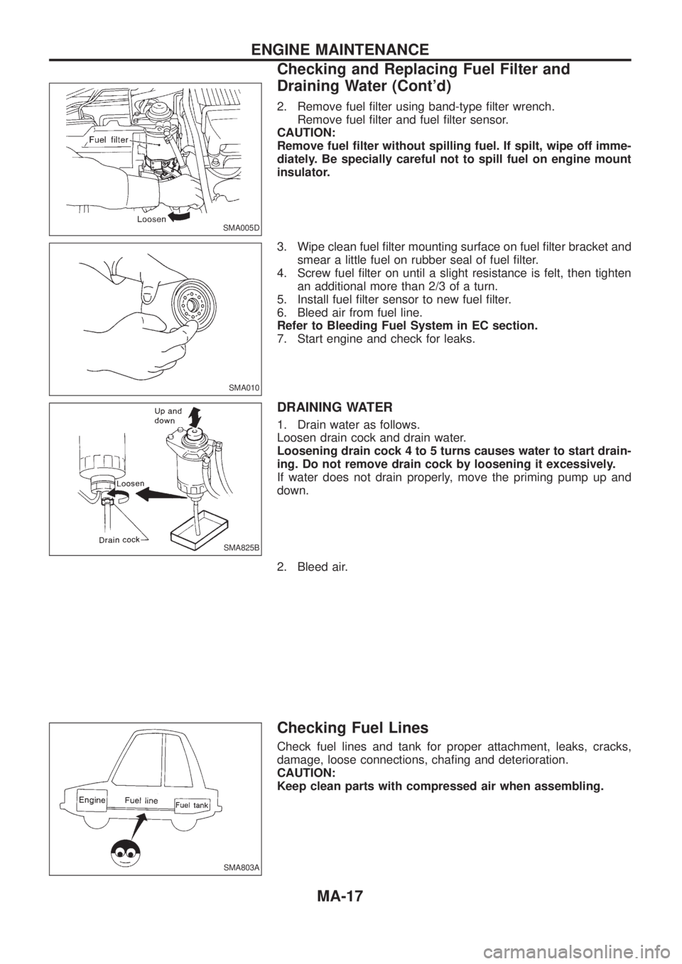
2. Remove fuel ®lter using band-type ®lter wrench.
Remove fuel ®lter and fuel ®lter sensor.
CAUTION:
Remove fuel ®lter without spilling fuel. If spilt, wipe off imme-
diately. Be specially careful not to spill fuel on engine mount
insulator.
3. Wipe clean fuel ®lter mounting surface on fuel ®lter bracket and
smear a little fuel on rubber seal of fuel ®lter.
4. Screw fuel ®lter on until a slight resistance is felt, then tighten
an additional more than 2/3 of a turn.
5. Install fuel ®lter sensor to new fuel ®lter.
6. Bleed air from fuel line.
Refer to Bleeding Fuel System in EC section.
7. Start engine and check for leaks.
DRAINING WATER
1. Drain water as follows.
Loosen drain cock and drain water.
Loosening drain cock 4 to 5 turns causes water to start drain-
ing. Do not remove drain cock by loosening it excessively.
If water does not drain properly, move the priming pump up and
down.
2. Bleed air.
Checking Fuel Lines
Check fuel lines and tank for proper attachment, leaks, cracks,
damage, loose connections, cha®ng and deterioration.
CAUTION:
Keep clean parts with compressed air when assembling.
SMA005D
SMA010
SMA825B
SMA803A
ENGINE MAINTENANCE
Checking and Replacing Fuel Filter and
Draining Water (Cont'd)
MA-17