2006 NISSAN PATROL tow
[x] Cancel search: towPage 985 of 1226
Maintenance Under Severe Driving Conditions
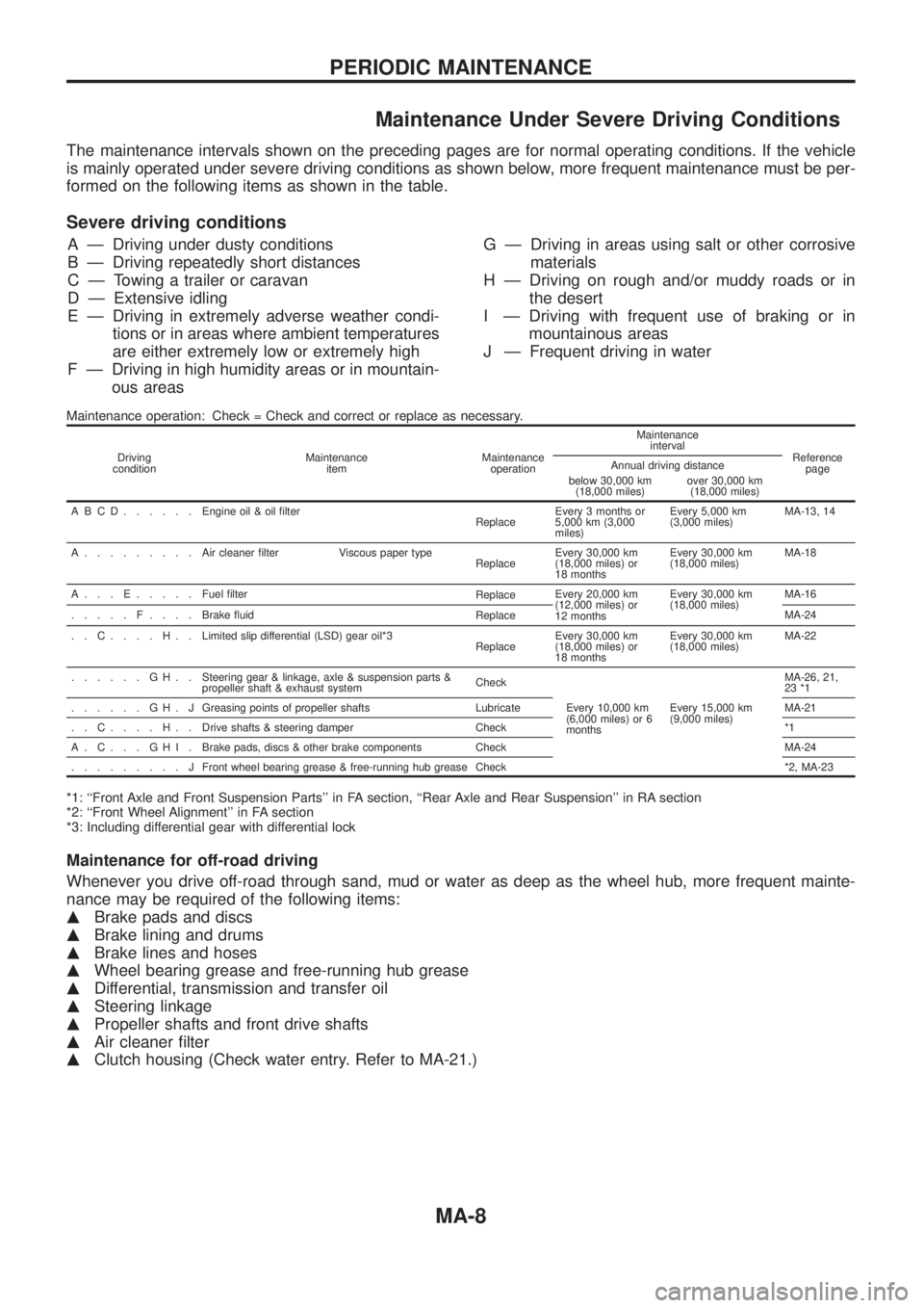
The maintenance intervals shown on the preceding pages are for normal operating conditions. If the vehicle
is mainly operated under severe driving conditions as shown below, more frequent maintenance must be per-
formed on the following items as shown in the table.
Severe driving conditions
A Ð Driving under dusty conditions
B Ð Driving repeatedly short distances
C Ð Towing a trailer or caravan
D Ð Extensive idling
E Ð Driving in extremely adverse weather condi-
tions or in areas where ambient temperatures
are either extremely low or extremely high
F Ð Driving in high humidity areas or in mountain-
ous areasG Ð Driving in areas using salt or other corrosive
materials
H Ð Driving on rough and/or muddy roads or in
the desert
I Ð Driving with frequent use of braking or in
mountainous areas
J Ð Frequent driving in water
Maintenance operation: Check = Check and correct or replace as necessary.
Driving
conditionMaintenance
itemMaintenance
operationMaintenance
interval
Reference
page Annual driving distance
below 30,000 km
(18,000 miles)over 30,000 km
(18,000 miles)
ABCD......Engine oil & oil ®lter
ReplaceEvery 3 months or
5,000 km (3,000
miles)Every 5,000 km
(3,000 miles)MA-13, 14
A.........Aircleaner ®lter Viscous paper type
ReplaceEvery 30,000 km
(18,000 miles) or
18 monthsEvery 30,000 km
(18,000 miles)MA-18
A...E.....Fuel ®lter
ReplaceEvery 20,000 km
(12,000 miles) or
12 monthsEvery 30,000 km
(18,000 miles)MA-16
.....F....Brake ¯uid
ReplaceMA-24
..C....H..Limited slip differential (LSD) gear oil*3
ReplaceEvery 30,000 km
(18,000 miles) or
18 monthsEvery 30,000 km
(18,000 miles)MA-22
......GH..Steering gear & linkage, axle & suspension parts &
propeller shaft & exhaust systemCheck
Every 10,000 km
(6,000 miles) or 6
monthsEvery 15,000 km
(9,000 miles)MA-26, 21,
23 *1
......GH.JGreasing points of propeller shafts Lubricate MA-21
..C....H..Drive shafts & steering damper Check *1
A.C...GHI.Brake pads, discs & other brake components Check MA-24
.........JFront wheel bearing grease & free-running hub grease Check *2, MA-23
*1: ``Front Axle and Front Suspension Parts'' in FA section, ``Rear Axle and Rear Suspension'' in RA section
*2: ``Front Wheel Alignment'' in FA section
*3: Including differential gear with differential lock
Maintenance for off-road driving
Whenever you drive off-road through sand, mud or water as deep as the wheel hub, more frequent mainte-
nance may be required of the following items:
mBrake pads and discs
mBrake lining and drums
mBrake lines and hoses
mWheel bearing grease and free-running hub grease
mDifferential, transmission and transfer oil
mSteering linkage
mPropeller shafts and front drive shafts
mAir cleaner ®lter
mClutch housing (Check water entry. Refer to MA-21.)
PERIODIC MAINTENANCE
MA-8
Page 1005 of 1226
Checking Body Corrosion
Visually check the body sheet metal panel for corrosion, paint damage (scratches, chipping, rubbing, etc.) or
damage to the anti-corrosion materials. In particular, check the following locations.
Hemmed portion
Hood front end, door lower end, trunk lid rear end, etc.
Panel joint
Side sill of rear fender and center pillar, rear wheel housing of rear fender, around strut tower in engine
compartment, etc.
Panel edge
Trunk lid opening, sunroof opening, fender wheelarch ¯ange, fuel ®ller lid ¯ange, around holes in panel, etc.
Parts contact
Waist molding, windshield molding, bumper, etc.
Protectors
Damage or condition of mudguard, fender protector, chipping protector, etc.
Anti-corrosion materials
Damage or separation of anti-corrosion materials under the body.
Drain holes
Condition of drain holes at door and side sill.
When repairing corroded areas, refer to the Corrosion Repair Manual.
CHASSIS AND BODY MAINTENANCE
MA-28
Page 1112 of 1226
System Components
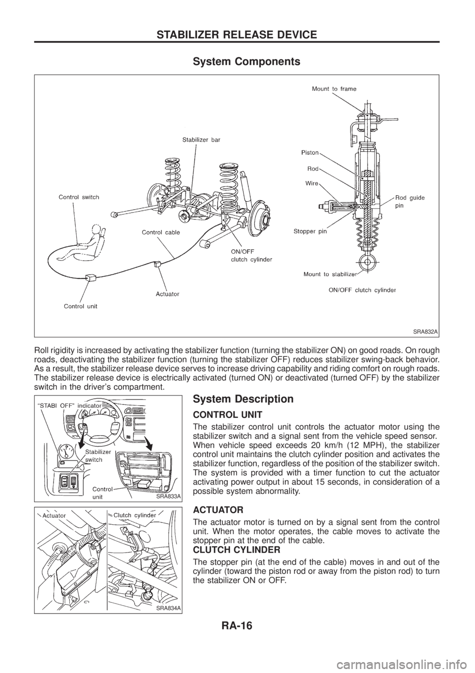
Roll rigidity is increased by activating the stabilizer function (turning the stabilizer ON) on good roads. On rough
roads, deactivating the stabilizer function (turning the stabilizer OFF) reduces stabilizer swing-back behavior.
As a result, the stabilizer release device serves to increase driving capability and riding comfort on rough roads.
The stabilizer release device is electrically activated (turned ON) or deactivated (turned OFF) by the stabilizer
switch in the driver's compartment.
System Description
CONTROL UNIT
The stabilizer control unit controls the actuator motor using the
stabilizer switch and a signal sent from the vehicle speed sensor.
When vehicle speed exceeds 20 km/h (12 MPH), the stabilizer
control unit maintains the clutch cylinder position and activates the
stabilizer function, regardless of the position of the stabilizer switch.
The system is provided with a timer function to cut the actuator
activating power output in about 15 seconds, in consideration of a
possible system abnormality.
ACTUATOR
The actuator motor is turned on by a signal sent from the control
unit. When the motor operates, the cable moves to activate the
stopper pin at the end of the cable.
CLUTCH CYLINDER
The stopper pin (at the end of the cable) moves in and out of the
cylinder (toward the piston rod or away from the piston rod) to turn
the stabilizer ON or OFF.
SRA832A
SRA833A
SRA834A
STABILIZER RELEASE DEVICE
RA-16
Page 1130 of 1226

Precautions for SRS ``AIR BAG'' and ``Seat Belt
Pre-tensioner'' Service
+Do not use a circuit tester to check SRS circuits unless instructed to in this Service Manual.
+Before servicing the SRS, turn ignition switch ``OFF'', disconnect both battery cables and wait for at least
3 minutes.
For approximately 3 minutes after the cables are removed, it is still possible for the air bag and seat belt
pre-tensioner to deploy. Therefore, do not work on any SRS connectors or wires until at least 3 minutes
have passed.
+Diagnosis sensor unit must always be installed with their arrow marks ``
S'' pointing towards the front of
the vehicle for proper operation. Also check diagnosis sensor unit for cracks, deformities or rust before
installation and replace as required.
+The spiral cable must be aligned with the neutral position since its rotations are limited. Do not attempt to
turn steering wheel or column after removal of steering gear.
+Handle air bag module carefully. Always place it with the pad side facing upward.
+Conduct self-diagnosis to check entire SRS for proper function after replacing any components.
+Instrument panel assembly should be replaced after air bag in¯ates if damaged.
Special Service Tools
Tool number
Tool nameDescriptionApplication
Seat belt
pre-ten-
sionerAir Bag
System
KV99106400
Deployment tool
NT357
Disposing of air bag mod-
ule
XX
KV99105300
Air bag module
bracket
NT354
Anchoring air bag module
ÐX
Special torx bit
NT361
Use for special bolts
[TAMPER RESISTANT
TORX (Size T50)]
a: 3.5 (0.138) dia.
b: 8.5 - 8.6
(0.335 - 0.339) dia.
c: approx. 10 (0.39) sq.
Unit: mm (in)ÐX
KV999R0020
Deployment tool
adapters for seat
belt pre-tensioner
NT721
XÐ
SUPPLEMENTAL RESTRAINT SYSTEM (SRS)
RS-8
Page 1170 of 1226
Supplemental Restraint System (SRS) ``AIR
BAG'' and ``SEAT BELT PRE-TENSIONER''
The Supplemental Restraint System such as ``AIR BAG'' and ``SEAT BELT PRE-TENSIONER'' used along with
a seat belt, helps to reduce the risk or severity of injury to the driver and front passenger in a frontal collision.
The SRS system composition which is available to NISSAN MODEL Y61 is as follows (The composition var-
ies according to the destination.):
Driver air bag module (located in the center of the steering wheel), front passenger air bag module (located
on the instrument panel on passenger side), seat belt pre-tensioner, a diagnosis sensor unit, warning lamp,
wiring harness and spiral cable.
Information necessary to service the system safely is included in theRS sectionof this Service Manual.
WARNING:
+To avoid rendering the SRS inoperative, which could increase the risk of personal injury or death
in the event of a collision which would result in air bag in¯ation, all maintenance must be performed
by an authorized NISSAN dealer.
+Improper maintenance, including incorrect removal and installation of the SRS, can lead to per-
sonal injury caused by unintentional activation of the system. For removal of Spiral Cable and Air
Bag Module, see the RS section.
+Do not use electrical test equipment on any circuit related to the SRS unless instructed to in this
Service Manual. Spiral cable and wiring harnesses covered with yellow insulation either just before
the harness connectors or for the complete harness are related to the SRS.
Precautions for Steering System
+Before disassembly, thoroughly clean the outside of the unit.
+Disassembly should be done in a clean work area. It is important to prevent the internal parts from
becoming contaminated by dirt or other foreign matter.
+Place disassembled parts in order, on a parts rack, for easier and proper assembly.
+Use nylon cloths or paper towels to clean the parts; common shop rags can leave lint that might
interfere with their operation.
+Before inspection or reassembly, carefully clean all parts with a general purpose, non-¯ammable
solvent.
+Before assembly, apply a coat of recommended ATF* to hydraulic parts. Vaseline may be applied
to O-rings and seals. Do not use any grease.
+Replace all gaskets, seals and O-rings. Avoid damaging O-rings, seals and gaskets during instal-
lation. Perform functional tests whenever designated.
*: Automatic Transmission Fluid type DEXRON
TMIII or equivalent
Special Service Tools
Tool number
Tool nameDescription
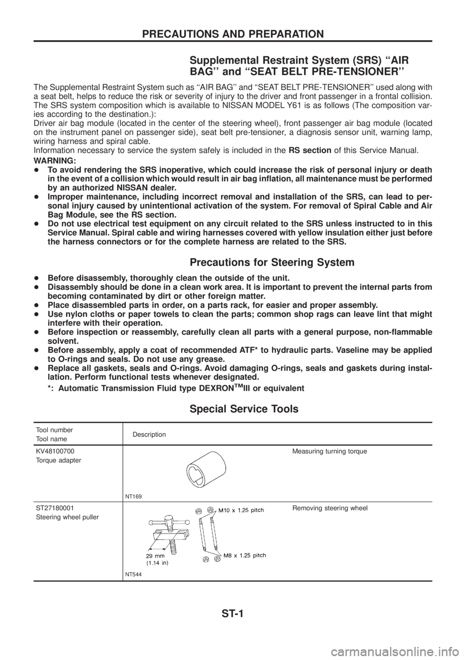
KV48100700
Torque adapter
NT169
Measuring turning torque
ST27180001
Steering wheel puller
NT544
Removing steering wheel
PRECAUTIONS AND PREPARATION
ST-1
Page 1181 of 1226
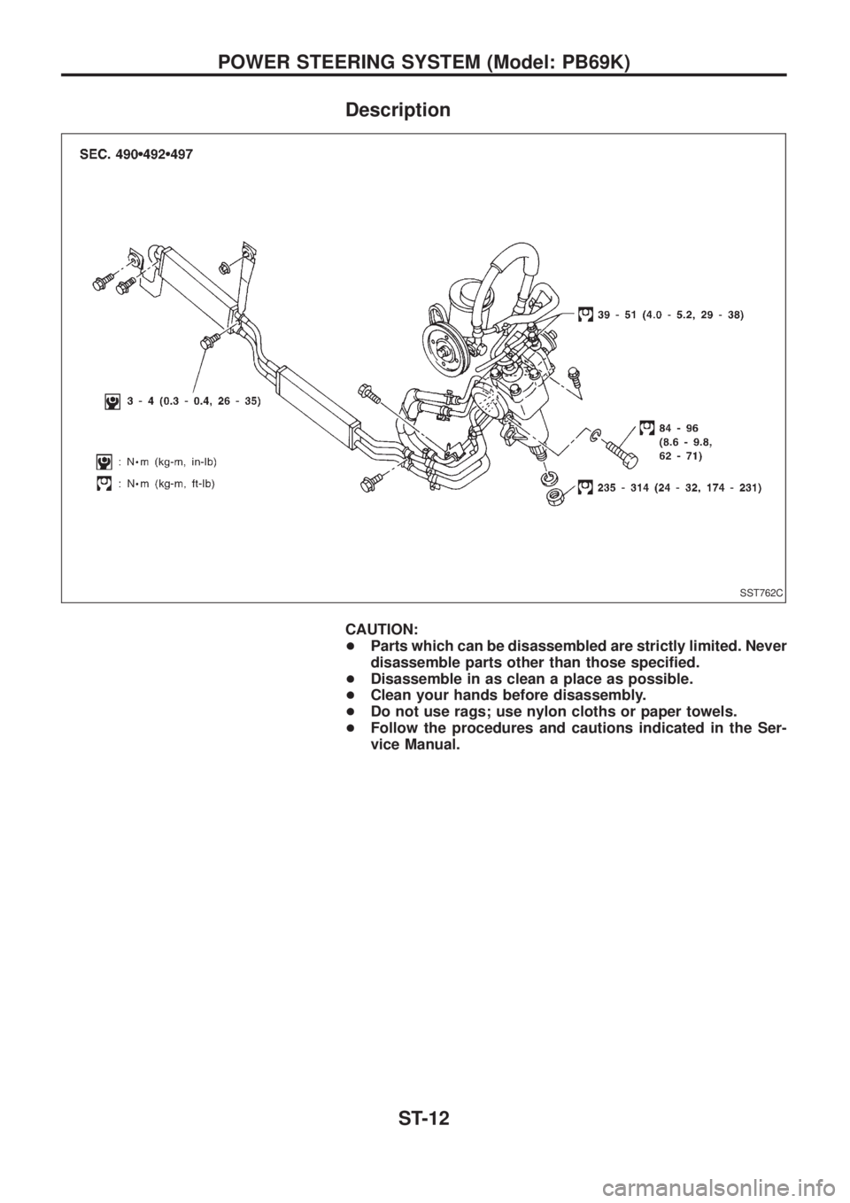
Description
CAUTION:
+Parts which can be disassembled are strictly limited. Never
disassemble parts other than those speci®ed.
+Disassemble in as clean a place as possible.
+Clean your hands before disassembly.
+Do not use rags; use nylon cloths or paper towels.
+Follow the procedures and cautions indicated in the Ser-
vice Manual.
SST762C
POWER STEERING SYSTEM (Model: PB69K)
ST-12
Page 1182 of 1226
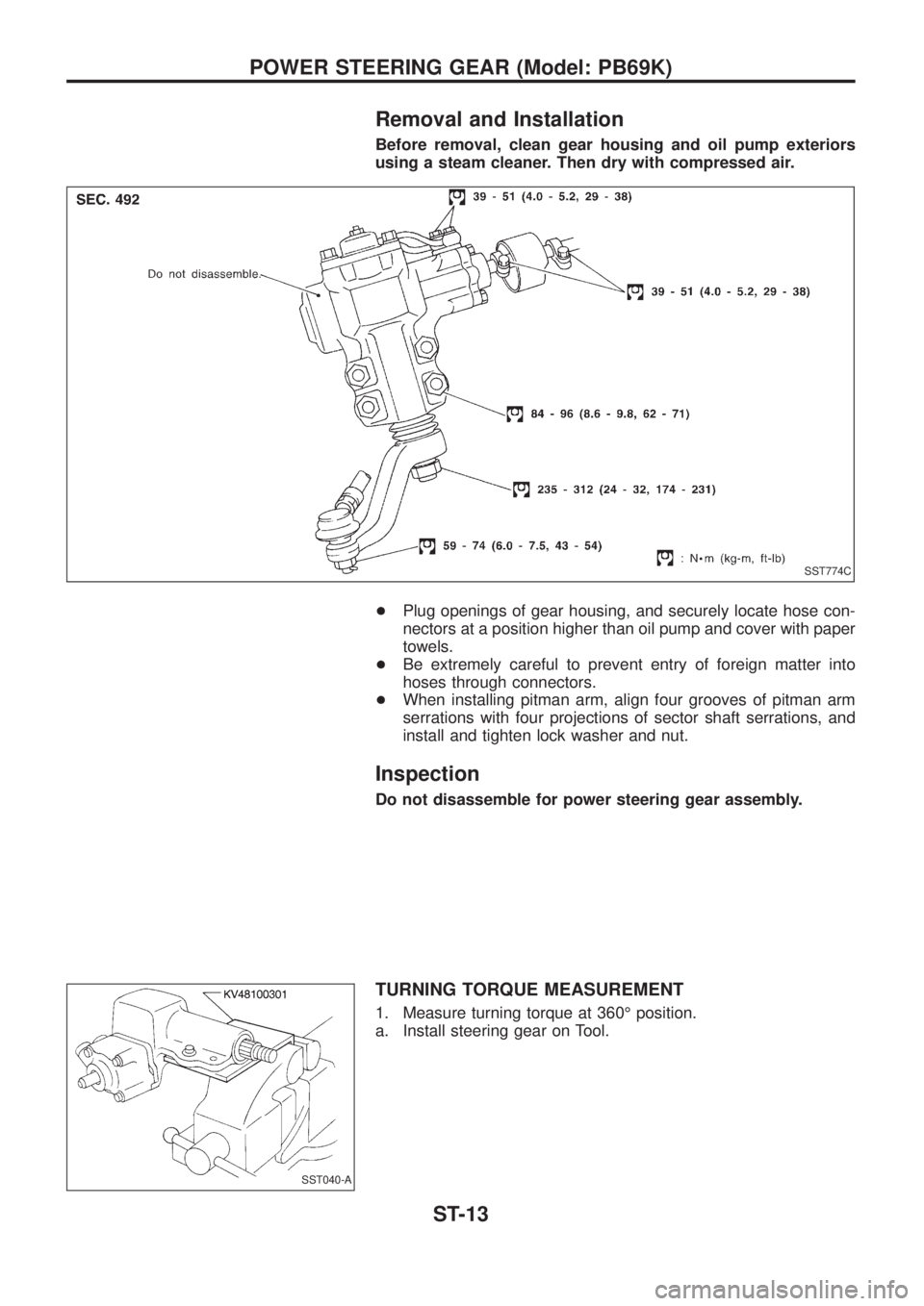
Removal and Installation
Before removal, clean gear housing and oil pump exteriors
using a steam cleaner. Then dry with compressed air.
+Plug openings of gear housing, and securely locate hose con-
nectors at a position higher than oil pump and cover with paper
towels.
+Be extremely careful to prevent entry of foreign matter into
hoses through connectors.
+When installing pitman arm, align four grooves of pitman arm
serrations with four projections of sector shaft serrations, and
install and tighten lock washer and nut.
Inspection
Do not disassemble for power steering gear assembly.
TURNING TORQUE MEASUREMENT
1. Measure turning torque at 360É position.
a. Install steering gear on Tool.
SST774C
SST040-A
POWER STEERING GEAR (Model: PB69K)
ST-13
Page 1186 of 1226
Inspection
PULLEY AND PULLEY SHAFT
+If pulley is cracked or deformed, replace it.
+If ¯uid leak is found around the pulley shaft, replace the oil seal.
Disassembly
CAUTION:
+Parts which can be disassembled are strictly limited. Never
disassemble parts other than those speci®ed.
+Disassemble in as clean a place as possible.
+Clean your hands before disassembly.
+Do not use rags; use nylon cloths or paper towels.
+When disassembling and reassembling, do not let foreign
matter enter or contact the parts.
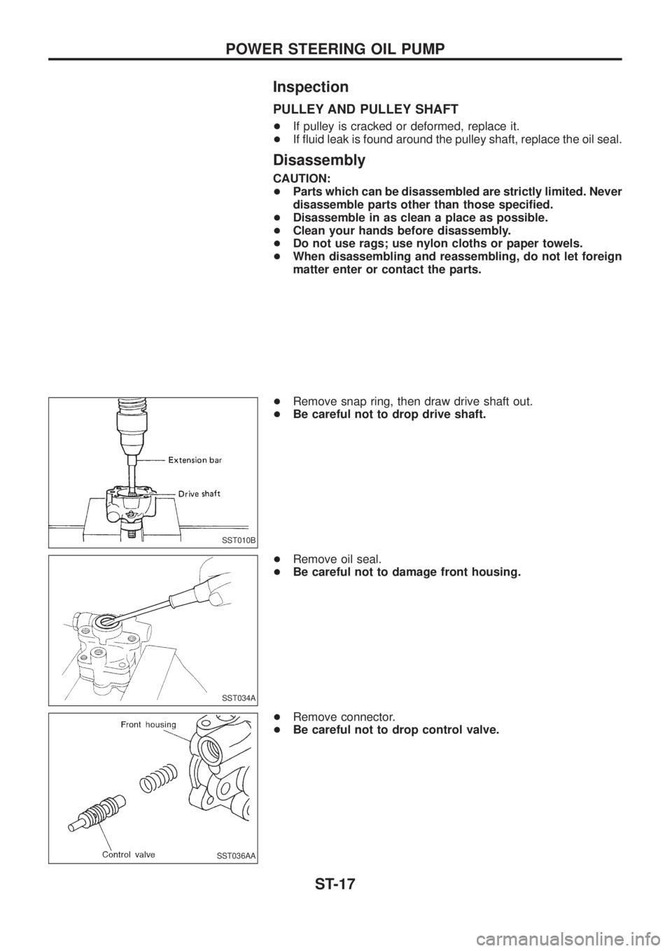
+Remove snap ring, then draw drive shaft out.
+Be careful not to drop drive shaft.
+Remove oil seal.
+Be careful not to damage front housing.
+Remove connector.
+Be careful not to drop control valve.
SST010B
SST034A
SST036AA
POWER STEERING OIL PUMP
ST-17