2006 NISSAN PATROL tow
[x] Cancel search: towPage 710 of 1226
Adjusting
Adjust valve clearance while engine is cold.
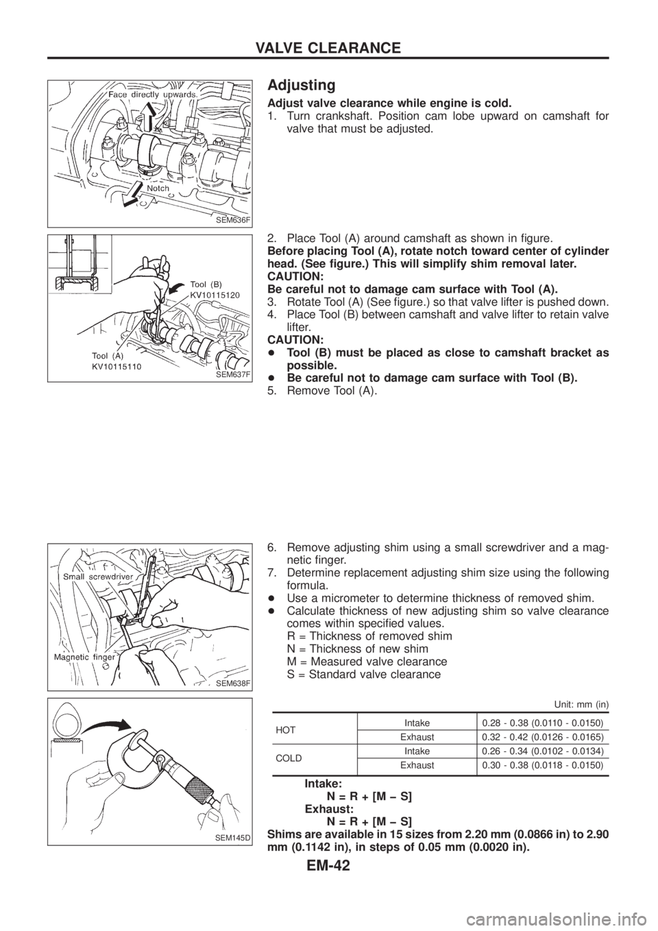
1. Turn crankshaft. Position cam lobe upward on camshaft for
valve that must be adjusted.
2. Place Tool (A) around camshaft as shown in ®gure.
Before placing Tool (A), rotate notch toward center of cylinder
head. (See ®gure.) This will simplify shim removal later.
CAUTION:
Be careful not to damage cam surface with Tool (A).
3. Rotate Tool (A) (See ®gure.) so that valve lifter is pushed down.
4. Place Tool (B) between camshaft and valve lifter to retain valve
lifter.
CAUTION:
+Tool (B) must be placed as close to camshaft bracket as
possible.
+Be careful not to damage cam surface with Tool (B).
5. Remove Tool (A).
6. Remove adjusting shim using a small screwdriver and a mag-
netic ®nger.
7. Determine replacement adjusting shim size using the following
formula.
+Use a micrometer to determine thickness of removed shim.
+Calculate thickness of new adjusting shim so valve clearance
comes within speci®ed values.
R = Thickness of removed shim
N = Thickness of new shim
M = Measured valve clearance
S = Standard valve clearance
Unit: mm (in)
HOTIntake 0.28 - 0.38 (0.0110 - 0.0150)
Exhaust 0.32 - 0.42 (0.0126 - 0.0165)
COLDIntake 0.26 - 0.34 (0.0102 - 0.0134)
Exhaust 0.30 - 0.38 (0.0118 - 0.0150)
Intake:
N=R+[MþS]
Exhaust:
N=R+[MþS]
Shims are available in 15 sizes from 2.20 mm (0.0866 in) to 2.90
mm (0.1142 in), in steps of 0.05 mm (0.0020 in).
SEM636F
SEM637F
SEM638F
SEM145D
VALVE CLEARANCE
EM-42
Page 723 of 1226
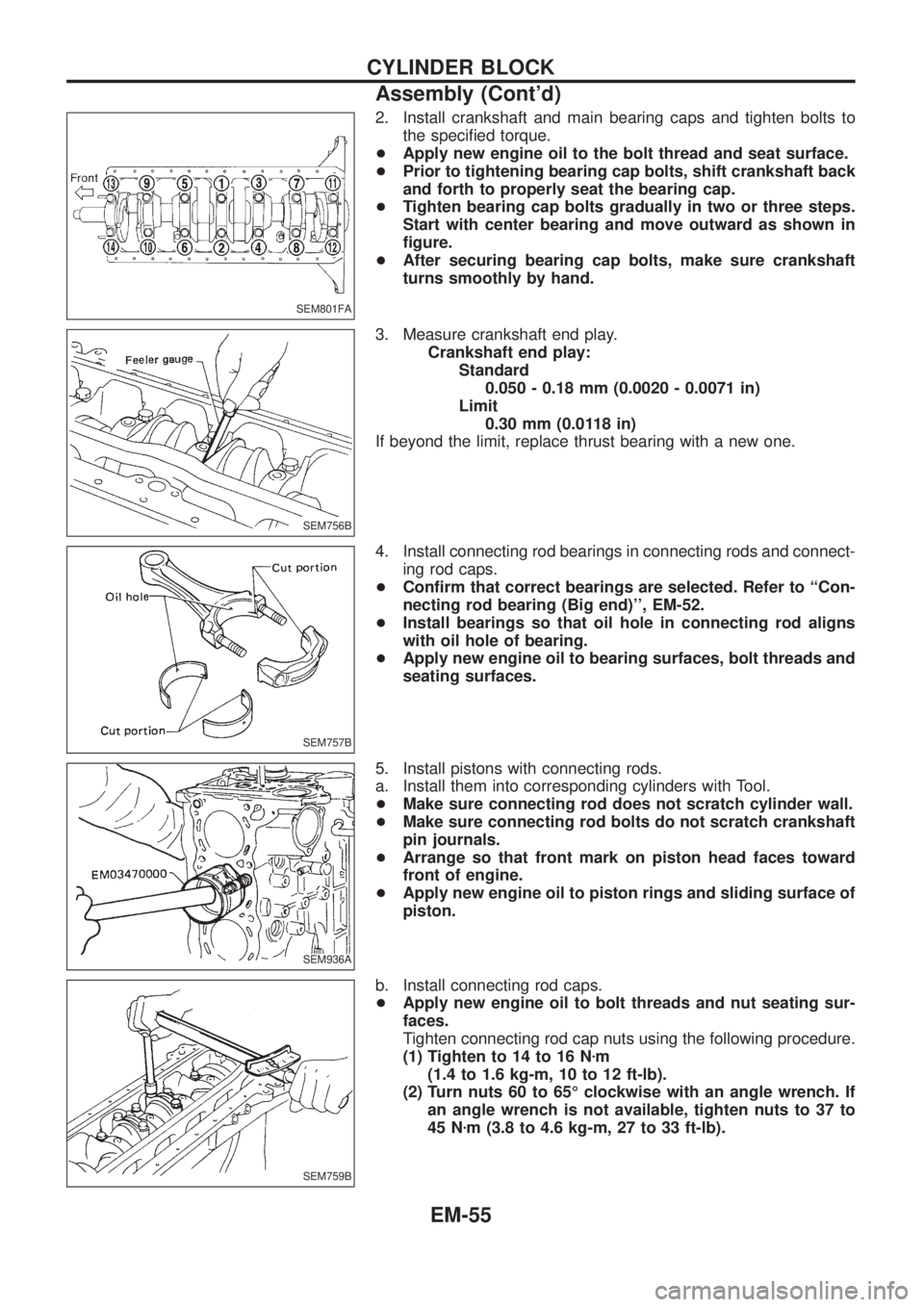
2. Install crankshaft and main bearing caps and tighten bolts to
the speci®ed torque.
+Apply new engine oil to the bolt thread and seat surface.
+Prior to tightening bearing cap bolts, shift crankshaft back
and forth to properly seat the bearing cap.
+Tighten bearing cap bolts gradually in two or three steps.
Start with center bearing and move outward as shown in
®gure.
+After securing bearing cap bolts, make sure crankshaft
turns smoothly by hand.
3. Measure crankshaft end play.
Crankshaft end play:
Standard
0.050 - 0.18 mm (0.0020 - 0.0071 in)
Limit
0.30 mm (0.0118 in)
If beyond the limit, replace thrust bearing with a new one.
4. Install connecting rod bearings in connecting rods and connect-
ing rod caps.
+Con®rm that correct bearings are selected. Refer to ``Con-
necting rod bearing (Big end)'', EM-52.
+Install bearings so that oil hole in connecting rod aligns
with oil hole of bearing.
+Apply new engine oil to bearing surfaces, bolt threads and
seating surfaces.
5. Install pistons with connecting rods.
a. Install them into corresponding cylinders with Tool.
+Make sure connecting rod does not scratch cylinder wall.
+Make sure connecting rod bolts do not scratch crankshaft
pin journals.
+Arrange so that front mark on piston head faces toward
front of engine.
+Apply new engine oil to piston rings and sliding surface of
piston.
b. Install connecting rod caps.
+Apply new engine oil to bolt threads and nut seating sur-
faces.
Tighten connecting rod cap nuts using the following procedure.
(1) Tighten to 14 to 16 Nzm
(1.4 to 1.6 kg-m, 10 to 12 ft-lb).
(2) Turn nuts 60 to 65É clockwise with an angle wrench. If
an angle wrench is not available, tighten nuts to 37 to
45 Nzm (3.8 to 4.6 kg-m, 27 to 33 ft-lb).
SEM801FA
SEM756B
SEM757B
SEM936A
SEM759B
CYLINDER BLOCK
Assembly (Cont'd)
EM-55
Page 773 of 1226
GENERAL INFORMATION
SECTION
GI
CONTENTS
PRECAUTIONS...............................................................1
Precaution for Supplemental Restraint System
(SRS) ``AIR BAG'' and ``SEAT BELT
PRE-TENSIONER'' ......................................................1
General Precautions ....................................................2
Precautions for Multiport Fuel Injection System
or ECCS Engine ..........................................................3
Precautions for Three Way Catalyst
(If so equipped)............................................................4
Precautions for Engine Oils .........................................4
Precautions for Fuel ....................................................5
Precautions for Air Conditioning ..................................5
HOW TO USE THIS MANUAL........................................6
HOW TO READ WIRING DIAGRAMS............................8
Sample/Wiring Diagram Ð EXAMPL Ð......................8
Description .................................................................10
HOW TO CHECK TERMINAL.......................................17
How to Probe Connectors .........................................17
How to Check Enlarged Contact Spring of
Terminal .....................................................................18
Waterproof Connector Inspection ..............................19
Terminal Lock Inspection ...........................................19
HOW TO PERFORM EFFICIENT DIAGNOSIS FOR
AN ELECTRICAL INCIDENT........................................20Work Flow ..................................................................20
Incident Simulation Tests ...........................................21
Circuit Inspection .......................................................24
HOW TO FOLLOW FLOW CHART IN TROUBLE
DIAGNOSES..................................................................30
How to Follow This Flow Chart .................................31
CONSULT CHECKING SYSTEM..................................33
Function and System Application ..............................33
Lithium Battery Replacement ....................................33
Checking Equipment..................................................33
Loading Procedure ....................................................34
CONSULT Data Link Connector (DLC) Circuit..........34
IDENTIFICATION INFORMATION.................................35
Model Variation ..........................................................35
Identi®cation Number .................................................36
Dimensions ................................................................38
Wheels & Tires ..........................................................38
LIFTING POINTS AND TOW TRUCK TOWING...........39
Screw Jack ................................................................39
Garage Jack and Safety Stand .................................39
2-pole Lift ...................................................................40
Tow Truck Towing ......................................................41
SAE J1930 TERMINOLOGY LIST................................43
SAE J1930 Terminology List .....................................43
GI
Page 812 of 1226
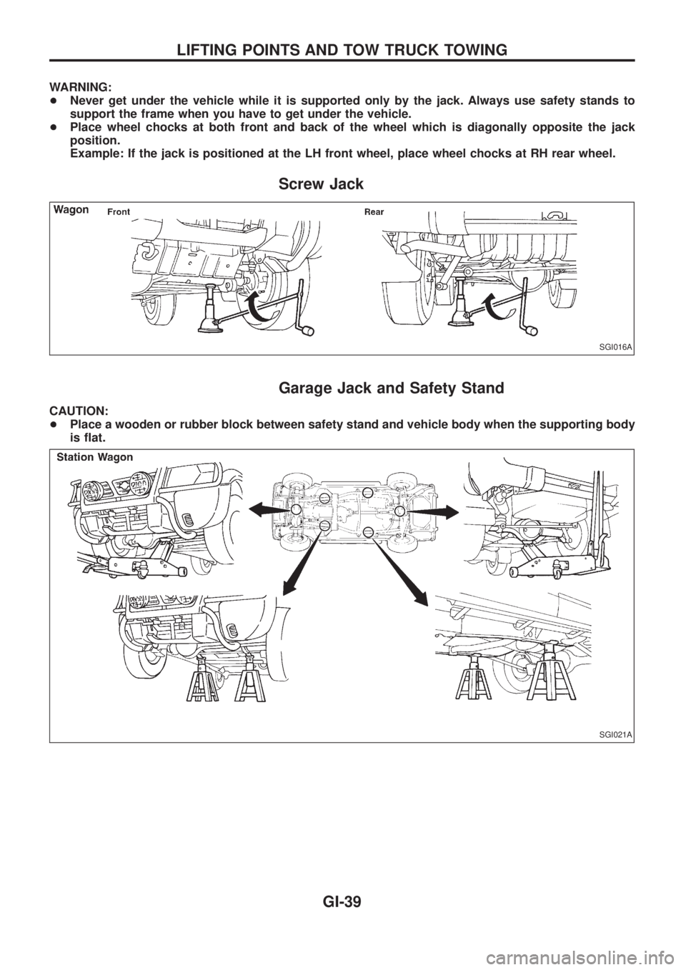
WARNING:
+Never get under the vehicle while it is supported only by the jack. Always use safety stands to
support the frame when you have to get under the vehicle.
+Place wheel chocks at both front and back of the wheel which is diagonally opposite the jack
position.
Example: If the jack is positioned at the LH front wheel, place wheel chocks at RH rear wheel.
Screw Jack
Garage Jack and Safety Stand
CAUTION:
+Place a wooden or rubber block between safety stand and vehicle body when the supporting body
is ¯at.
SGI016A
SGI021A
LIFTING POINTS AND TOW TRUCK TOWING
GI-39
Page 813 of 1226
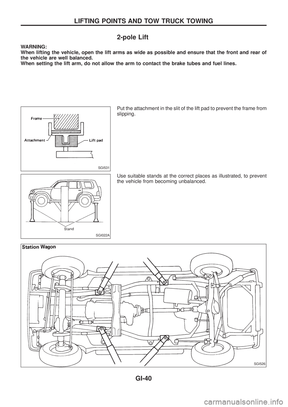
2-pole Lift
WARNING:
When lifting the vehicle, open the lift arms as wide as possible and ensure that the front and rear of
the vehicle are well balanced.
When setting the lift arm, do not allow the arm to contact the brake tubes and fuel lines.
Put the attachment in the slit of the lift pad to prevent the frame from
slipping.
Use suitable stands at the correct places as illustrated, to prevent
the vehicle from becoming unbalanced.
SGI531
SGI022A
SGI526
LIFTING POINTS AND TOW TRUCK TOWING
GI-40
Page 814 of 1226
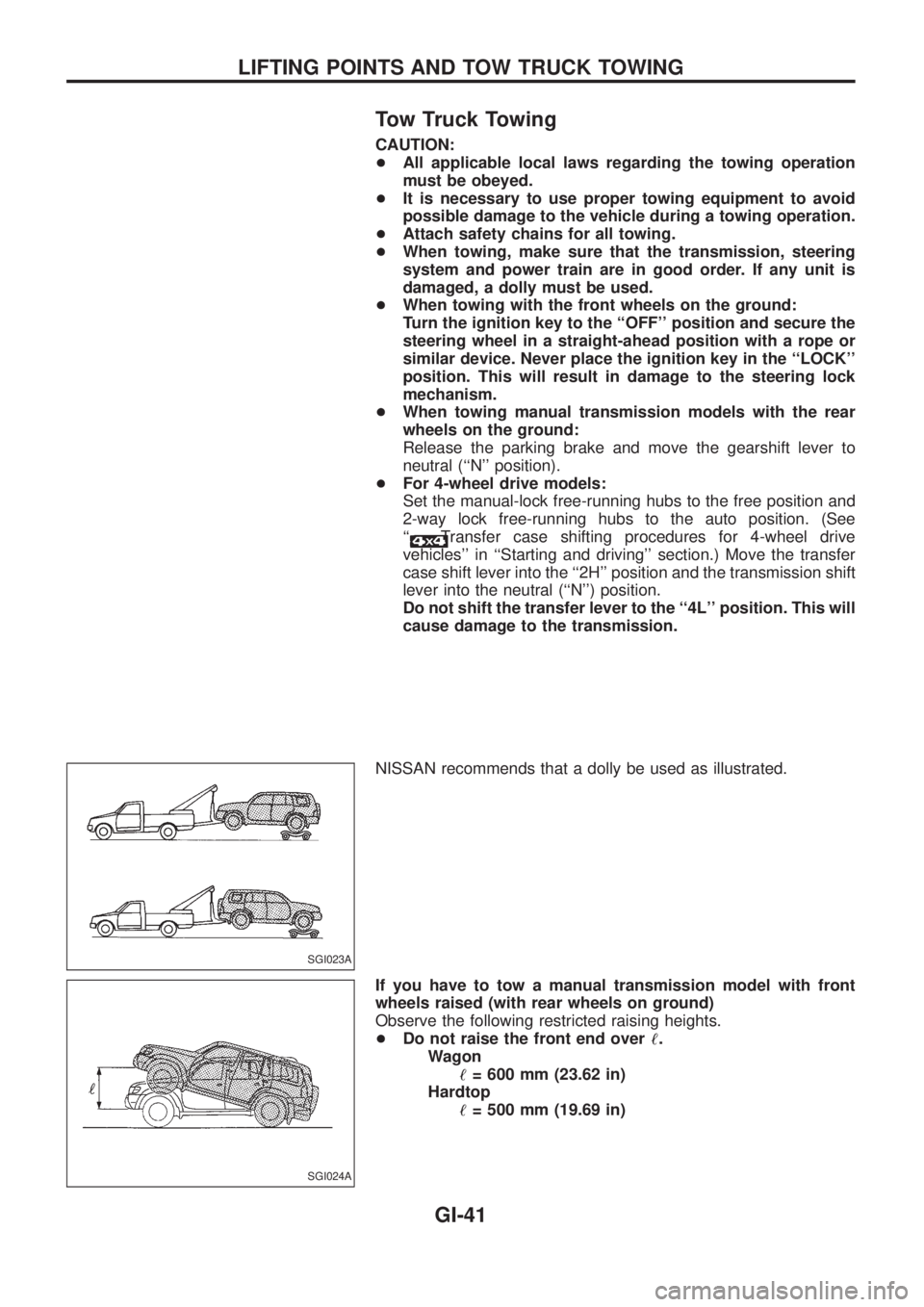
Tow Truck Towing
CAUTION:
+All applicable local laws regarding the towing operation
must be obeyed.
+It is necessary to use proper towing equipment to avoid
possible damage to the vehicle during a towing operation.
+Attach safety chains for all towing.
+When towing, make sure that the transmission, steering
system and power train are in good order. If any unit is
damaged, a dolly must be used.
+When towing with the front wheels on the ground:
Turn the ignition key to the ``OFF'' position and secure the
steering wheel in a straight-ahead position with a rope or
similar device. Never place the ignition key in the ``LOCK''
position. This will result in damage to the steering lock
mechanism.
+When towing manual transmission models with the rear
wheels on the ground:
Release the parking brake and move the gearshift lever to
neutral (``N'' position).
+For 4-wheel drive models:
Set the manual-lock free-running hubs to the free position and
2-way lock free-running hubs to the auto position. (See
``
Transfer case shifting procedures for 4-wheel drive
vehicles'' in ``Starting and driving'' section.) Move the transfer
case shift lever into the ``2H'' position and the transmission shift
lever into the neutral (``N'') position.
Do not shift the transfer lever to the ``4L'' position. This will
cause damage to the transmission.
NISSAN recommends that a dolly be used as illustrated.
If you have to tow a manual transmission model with front
wheels raised (with rear wheels on ground)
Observe the following restricted raising heights.
+Do not raise the front end over!.
Wagon
!= 600 mm (23.62 in)
Hardtop
!= 500 mm (19.69 in)
SGI023A
SGI024A
LIFTING POINTS AND TOW TRUCK TOWING
GI-41
Page 815 of 1226
If you have to tow an automatic transmission model
with four wheels on ground or tow an automatic
transmission model with front wheels raised (with rear
wheels on ground)
Observe the following restricted towing speeds, distances and rais-
ing heights.
+Speed: Below 50 km/h (30 MPH)
+Distance: Less than 65 km (40 miles)
+Do not raise the front end over!.
Wagon
!= 600 mm (23.62 in)
Hardtop
!= 500 mm (19.69 in)
If the speed, distance or height must necessarily be greater,
remove the propeller shaft beforehand to prevent damage to the
transmission.
CAUTION:
+Never tow your vehicle from the rear (i.e., backward) with
four wheels on the ground as this may cause serious and
expensive damage to the transmission.
+Be sure to place the transfer case shift lever into the ``2H''
position and the transmission shift lever into the neutral
(``N'') position if the vehicle is to be towed.
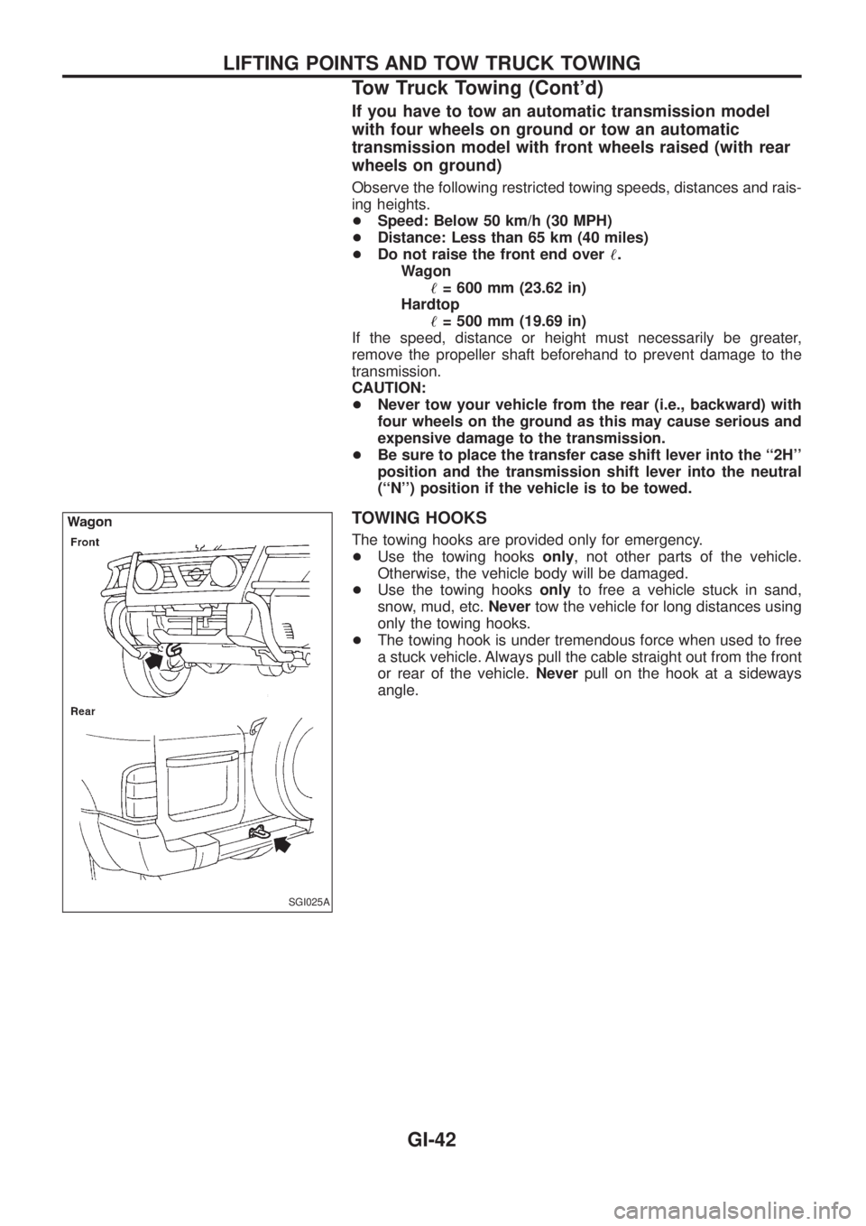
TOWING HOOKS
The towing hooks are provided only for emergency.
+Use the towing hooksonly, not other parts of the vehicle.
Otherwise, the vehicle body will be damaged.
+Use the towing hooksonlyto free a vehicle stuck in sand,
snow, mud, etc.Nevertow the vehicle for long distances using
only the towing hooks.
+The towing hook is under tremendous force when used to free
a stuck vehicle. Always pull the cable straight out from the front
or rear of the vehicle.Neverpull on the hook at a sideways
angle.
SGI025A
LIFTING POINTS AND TOW TRUCK TOWING
Tow Truck Towing (Cont'd)
GI-42
Page 954 of 1226
Tie-rod ball joints.............................................ST-19
Tie-rod .............................................................ST-19
Timing belt......................................................EM-15
Tire rotation ....................................................MA-25
Tire size ...........................................................GI-38
Tooth contact (front ®nal drive 4WD) .............PD-29
Tooth contact diff. ...........................................PD-29
Tow truck towing ..............................................GI-41
Towing point.....................................................GI-42
Transfer case ..................................................TF-10
Transfer ¯uid replacement .............................MA-21
Transfer serial number ....................................GI-37
Transmission case (M/T) ..................................MT-9
Trim .................................................................BT-14
Trouble diagnoses ...........................................GI-30
Turbocharger charge air cooler .....................EM-27
Turbocharger ..................................................EM-23
Two-pole lift .....................................................GI-40
U
Under body .....................................................BT-51
V
VSS - Wiring diagram ....................................EC-82
Vacuum hose (brake system) ........................BR-17
Vacuum hose (brake system) ........................BR-18
Vacuum hose drawing (ECCS) ......................EC-13
Valve clearance..............................................EM-40
Valve guide ....................................................EM-31
Valve lifter ......................................................EM-35
Valve seat ......................................................EM-32
Valve spring ...................................................EM-34Vehicle identi®cation number...........................GI-36
Vehicle speed sensor (VSS) ..........................EC-82
Viscosity number (SAE) .................................MA-10
W
WARN - Wiring diagram ...............................EL-123
WINDOW - Wiring diagram ..........................EL-198
WIP/R - Wiring diagram ................................EL-146
WIPER - Wiring diagram ..............................EL-142
Warning chime ..............................................EL-135
Warning lamps ..............................................EL-121
Washer, front .................................................EL-141
Washer, rear..................................................EL-145
Water pump ....................................................LC-10
Water temperature gauge .............................EL-102
Weatherstrip - See Exterior ............................BT-26
Wheel alignment (front) ....................................FA-8
Wheel bearing (front axle) ................................FA-5
Wheel bearing (rear) ........................................RA-5
Wheel hub (front) ............................................FA-14
Wheel size .......................................................GI-38
Window, back door .........................................BT-45
Window, door ....................................................BT-9
Window, rear side ...........................................BT-44
Window, side - See Rear side window ...........BT-44
Windshield.......................................................BT-42
Wiper deicer ..................................................EL-166
Wiper, front....................................................EL-141
Wiper, rear ....................................................EL-145
Wiring diagram (cell code) list ......................EL-315
Wiring diagrams.................................................GI-8
Withdrawal lever (clutch) ................................CL-11
ALPHABETICAL INDEX
IDX-7