2006 NISSAN PATROL Air conditioning
[x] Cancel search: Air conditioningPage 150 of 1226
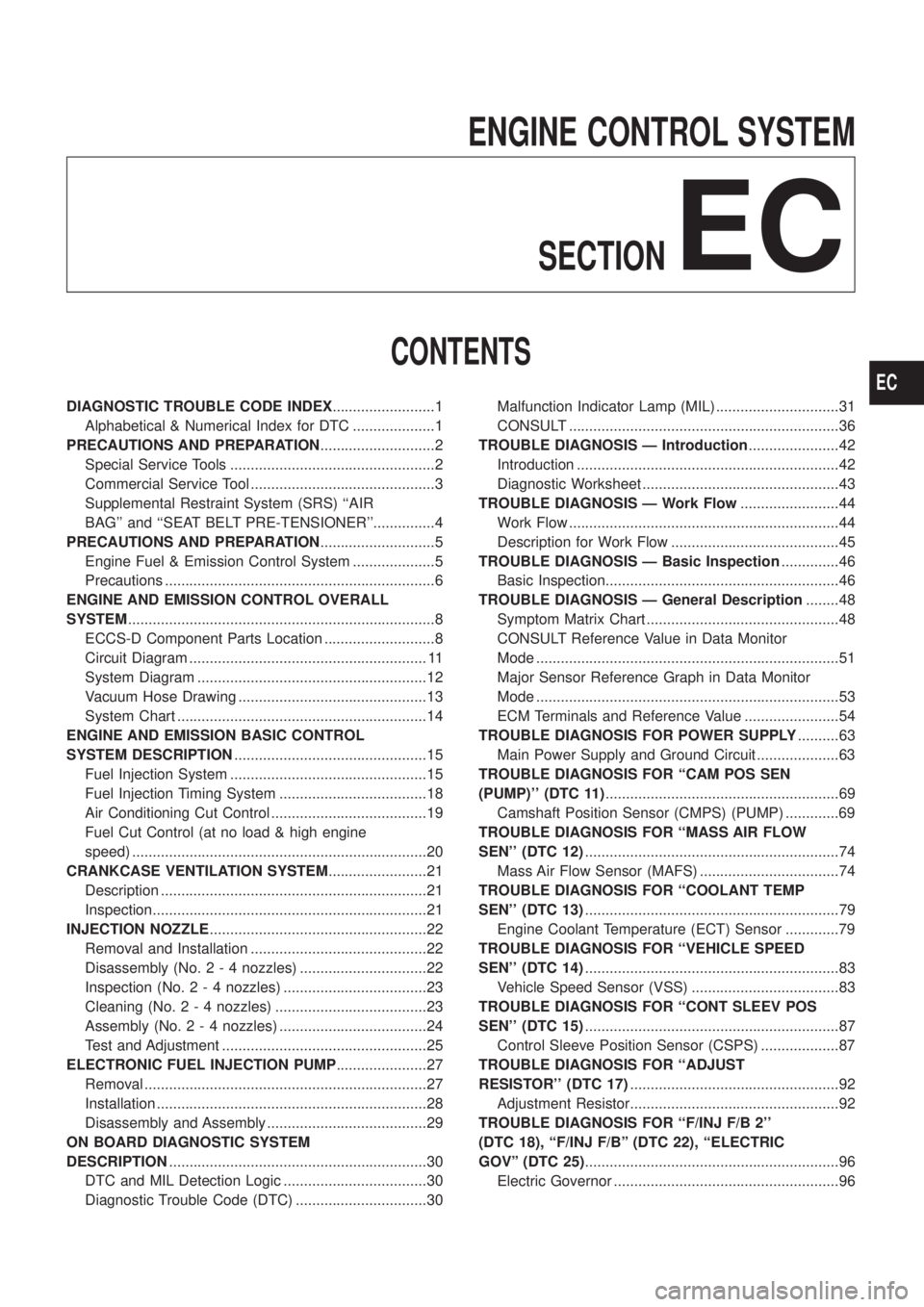
ENGINE CONTROL SYSTEMSECTION
EC
CONTENTS
DIAGNOSTIC TROUBLE CODE INDEX .........................1
Alphabetical & Numerical Index for DTC ....................1
PRECAUTIONS AND PREPARATION ............................2
Special Service Tools ..................................................2
Commercial Service Tool .............................................3
Supplemental Restraint System (SRS) ``AIR
BAG'' and ``SEAT BELT PRE-TENSIONER''...............4
PRECAUTIONS AND PREPARATION ............................5
Engine Fuel & Emission Control System ....................5
Precautions ..................................................................6
ENGINE AND EMISSION CONTROL OVERALL
SYSTEM ........................................................................\
...8
ECCS-D Component Parts Location ...........................8
Circuit Diagram .......................................................... 11
System Diagram ........................................................12
Vacuum Hose Drawing ..............................................13
System Chart .............................................................14
ENGINE AND EMISSION BASIC CONTROL
SYSTEM DESCRIPTION ...............................................15
Fuel Injection System ................................................15
Fuel Injection Timing System ....................................18
Air Conditioning Cut Control ......................................19
Fuel Cut Control (at no load & high engine
speed) ........................................................................\
20
CRANKCASE VENTILATION SYSTEM ........................21
Description .................................................................21
Inspection...................................................................21
INJECTION NOZZLE .....................................................22
Removal and Installation ...........................................22
Disassembly (No. 2 - 4 nozzles) ...............................22
Inspection (No. 2 - 4 nozzles) ...................................23
Cleaning (No. 2 - 4 nozzles) .....................................23
Assembly (No. 2 - 4 nozzles) ....................................24
Test and Adjustment ..................................................25
ELECTRONIC FUEL INJECTION PUMP ......................27
Removal .....................................................................27
Installation ..................................................................28
Disassembly and Assembly .......................................29
ON BOARD DIAGNOSTIC SYSTEM
DESCRIPTION ...............................................................30
DTC and MIL Detection Logic ...................................30
Diagnostic Trouble Code (DTC) ................................30 Malfunction Indicator Lamp (MIL) ..............................31
CONSULT ..................................................................36
TROUBLE DIAGNOSIS Ð Introduction ......................42
Introduction ................................................................42
Diagnostic Worksheet ................................................43
TROUBLE DIAGNOSIS Ð Work Flow ........................44
Work Flow ..................................................................44
Description for Work Flow .........................................45
TROUBLE DIAGNOSIS Ð Basic Inspection ..............46
Basic Inspection.........................................................46
TROUBLE DIAGNOSIS Ð General Description ........48
Symptom Matrix Chart ...............................................48
CONSULT Reference Value in Data Monitor
Mode ........................................................................\
..51
Major Sensor Reference Graph in Data Monitor
Mode ........................................................................\
..53
ECM Terminals and Reference Value .......................54
TROUBLEDIAGNOSISFORPOWERSUPPLY ..........63
MainPowerSupplyandGroundCircuit....................63
TROUBLE DIAGNOSIS FOR ``CAM POS SEN
(PUMP)''(DTC11) .........................................................69
CamshaftPositionSensor(CMPS)(PUMP).............69
TROUBLEDIAGNOSISFOR``MASSAIRFLOW
SEN''(DTC12) ..............................................................74
MassAirFlowSensor(MAFS)..................................74
TROUBLEDIAGNOSISFOR``COOLANTTEMP
SEN''(DTC13) ..............................................................79
EngineCoolantTemperature(ECT)Sensor.............79
TROUBLEDIAGNOSISFOR``VEHICLESPEED
SEN''(DTC14) ..............................................................83
VehicleSpeedSensor(VSS)....................................83
TROUBLEDIAGNOSISFOR``CONTSLEEVPOS
SEN''(DTC15) ..............................................................87
ControlSleevePositionSensor(CSPS)...................87
TROUBLEDIAGNOSISFOR``ADJUST
RESISTOR''(DTC17) ...................................................92
AdjustmentResistor...................................................92
TROUBLEDIAGNOSISFOR``F/INJF/B2''
(DTC18),``F/INJF/B''(DTC22),``ELECTRIC
GOV''(DTC25) ..............................................................96
ElectricGovernor.......................................................96
EC
Page 165 of 1226
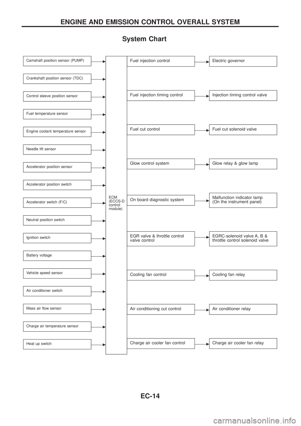
System Chart
Camshaft position sensor (PUMP)c
ECM
(ECCS-D
control
module)
Crankshaft position sensor (TDC)c
Control sleeve position sensorc
Fuel temperature sensorc
Engine coolant temperature sensorc
Needle lift sensorc
Accelerator position sensorc
Accelerator position switchc
Accelerator switch (F/C)c
Neutral position switchc
Ignition switchc
Battery voltagec
Vehicle speed sensorc
Air conditioner switchc
Mass air ¯ow sensorc
Charge air temperature sensorc
Heat up switchc
Fuel injection controlcElectric governor
Fuel injection timing controlcInjection timing control valve
Fuel cut controlcFuel cut solenoid valve
Glow control systemcGlow relay & glow lamp
On board diagnostic systemcMalfunction indicator lamp
(On the instrument panel)
EGR valve & throttle control
valve controlcEGRC-solenoid valve A, B &
throttle control solenoid valve
Cooling fan controlcCooling fan relay
Air conditioning cut controlcAir conditioner relay
Charge air cooler fan controlcCharge air cooler fan relay
ENGINE AND EMISSION CONTROL OVERALL SYSTEM
EC-14
Page 170 of 1226
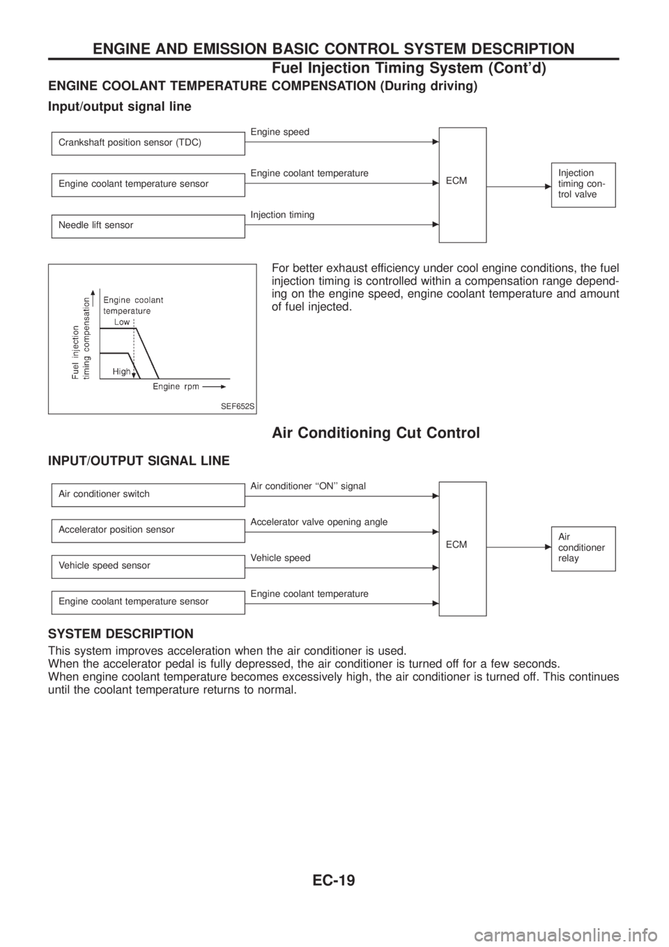
ENGINE COOLANT TEMPERATURE COMPENSATION (During driving)
Input/output signal line
Crankshaft position sensor (TDC)cEngine speed
ECM
c
Injection
timing con-
trol valveEngine coolant temperature sensorcEngine coolant temperature
Needle lift sensor
cInjection timing
For better exhaust efficiency under cool engine conditions, the fuel
injection timing is controlled within a compensation range depend-
ing on the engine speed, engine coolant temperature and amount
of fuel injected.
Air Conditioning Cut Control
INPUT/OUTPUT SIGNAL LINE
Air conditioner switchcAir conditioner ``ON'' signal
ECM
cAir
conditioner
relayAccelerator position sensorcAccelerator valve opening angle
Vehicle speed sensor
cVehicle speed
Engine coolant temperature sensor
cEngine coolant temperature
SYSTEM DESCRIPTION
This system improves acceleration when the air conditioner is used.
When the accelerator pedal is fully depressed, the air conditioner is turned off for a few seconds.
When engine coolant temperature becomes excessively high, the air conditioner is turned off. This continues
until the coolant temperature returns to normal.
SEF652S
ENGINE AND EMISSION BASIC CONTROL SYSTEM DESCRIPTION
Fuel Injection Timing System (Cont'd)
EC-19
Page 773 of 1226
GENERAL INFORMATION
SECTION
GI
CONTENTS
PRECAUTIONS...............................................................1
Precaution for Supplemental Restraint System
(SRS) ``AIR BAG'' and ``SEAT BELT
PRE-TENSIONER'' ......................................................1
General Precautions ....................................................2
Precautions for Multiport Fuel Injection System
or ECCS Engine ..........................................................3
Precautions for Three Way Catalyst
(If so equipped)............................................................4
Precautions for Engine Oils .........................................4
Precautions for Fuel ....................................................5
Precautions for Air Conditioning ..................................5
HOW TO USE THIS MANUAL........................................6
HOW TO READ WIRING DIAGRAMS............................8
Sample/Wiring Diagram Ð EXAMPL Ð......................8
Description .................................................................10
HOW TO CHECK TERMINAL.......................................17
How to Probe Connectors .........................................17
How to Check Enlarged Contact Spring of
Terminal .....................................................................18
Waterproof Connector Inspection ..............................19
Terminal Lock Inspection ...........................................19
HOW TO PERFORM EFFICIENT DIAGNOSIS FOR
AN ELECTRICAL INCIDENT........................................20Work Flow ..................................................................20
Incident Simulation Tests ...........................................21
Circuit Inspection .......................................................24
HOW TO FOLLOW FLOW CHART IN TROUBLE
DIAGNOSES..................................................................30
How to Follow This Flow Chart .................................31
CONSULT CHECKING SYSTEM..................................33
Function and System Application ..............................33
Lithium Battery Replacement ....................................33
Checking Equipment..................................................33
Loading Procedure ....................................................34
CONSULT Data Link Connector (DLC) Circuit..........34
IDENTIFICATION INFORMATION.................................35
Model Variation ..........................................................35
Identi®cation Number .................................................36
Dimensions ................................................................38
Wheels & Tires ..........................................................38
LIFTING POINTS AND TOW TRUCK TOWING...........39
Screw Jack ................................................................39
Garage Jack and Safety Stand .................................39
2-pole Lift ...................................................................40
Tow Truck Towing ......................................................41
SAE J1930 TERMINOLOGY LIST................................43
SAE J1930 Terminology List .....................................43
GI
Page 778 of 1226
Dispose of used oil and used oil ®lters through authorized waste
disposal contractors to licensed waste disposal sites, or to the
waste oil reclamation trade. If in doubt, contact the local authority
for advice on disposal facilities.
It is illegal to pour used oil on to the ground, down sewers or drains,
or into water courses.
The regulations concerning the pollution of the environment
will vary from country to country.
Precautions for Fuel
GASOLINE ENGINE:
Three way catalyst equipped models ... unleaded gasoline of at
least 91 octane (RON)
CAUTION:
Do not use leaded gasoline. Using leaded gasoline will dam-
age the three way catalyst.
Except for the above models ... unleaded or leaded gasoline of
above 88 octane (RON)
Use unleaded fuel if instructed on the fuel ®ller lid.
DIESEL ENGINE*:
Diesel fuel of above 45 cetane for TD42 engine and above 50 cet-
ane for RD28ET engine
* If two types of diesel fuel are available, use summer or winter
fuel properly according to the following temperature conditions.
+Above þ7ÉC (20ÉF) ... Summer type diesel fuel.
+Below þ7ÉC (20ÉF) ... Winter type diesel fuel.
CAUTION:
+Do not use home heating oil, gasoline, or other alternate
fuels in your diesel engine. The use of those can cause
engine damage.
+Do not use summer fuel at temperature below þ7ÉC (20ÉF).
The cold temperature will cause wax to form in the fuel. As
a result, it may prevent the engine from running smoothly.
+Do not add gasoline or other alternate fuels to diesel fuel.
Precautions for Air Conditioning
Use an approved refrigerant recovery unit any time the air condi-
tioning system must be discharged. Refer to HA section (``HFC-
134a (R-134a) Service Procedure'', ``SERVICE PROCEDURES'')
for speci®c instructions.
PRECAUTIONS
Precautions for Engine Oils (Cont'd)
GI-5
Page 823 of 1226
General Refrigerant Precautions
WARNING:
+Do not release refrigerant into the air. Use approved recovery/recycling equipment to capture the
refrigerant every time an air conditioning system is discharged.
+Always wear eye and hand protection (goggles and gloves) when working with any refrigerant or
air conditioning system.
+Do not store or heat refrigerant containers above 52ÉC.
+Do not heat a refrigerant container with an open ¯ame; if container warming is required, place the
bottom of the container in a warm pail of water.
+Do not intentionally drop, puncture, or incinerate refrigerant containers.
+Keep refrigerant away from open ¯ames: poisonous gas will be produced if refrigerant burns.
+Refrigerant will displace oxygen, therefore be certain to work in well ventilated areas to prevent
suffocation.
+Do not introduce compressed air to any refrigerant container or refrigerant component.
Precautions for Refrigerant Connection
A new type refrigerant connection has been introduced to all refrigerant lines except the following location.
+Expansion valve to cooling unit
+A part of high-pressure line
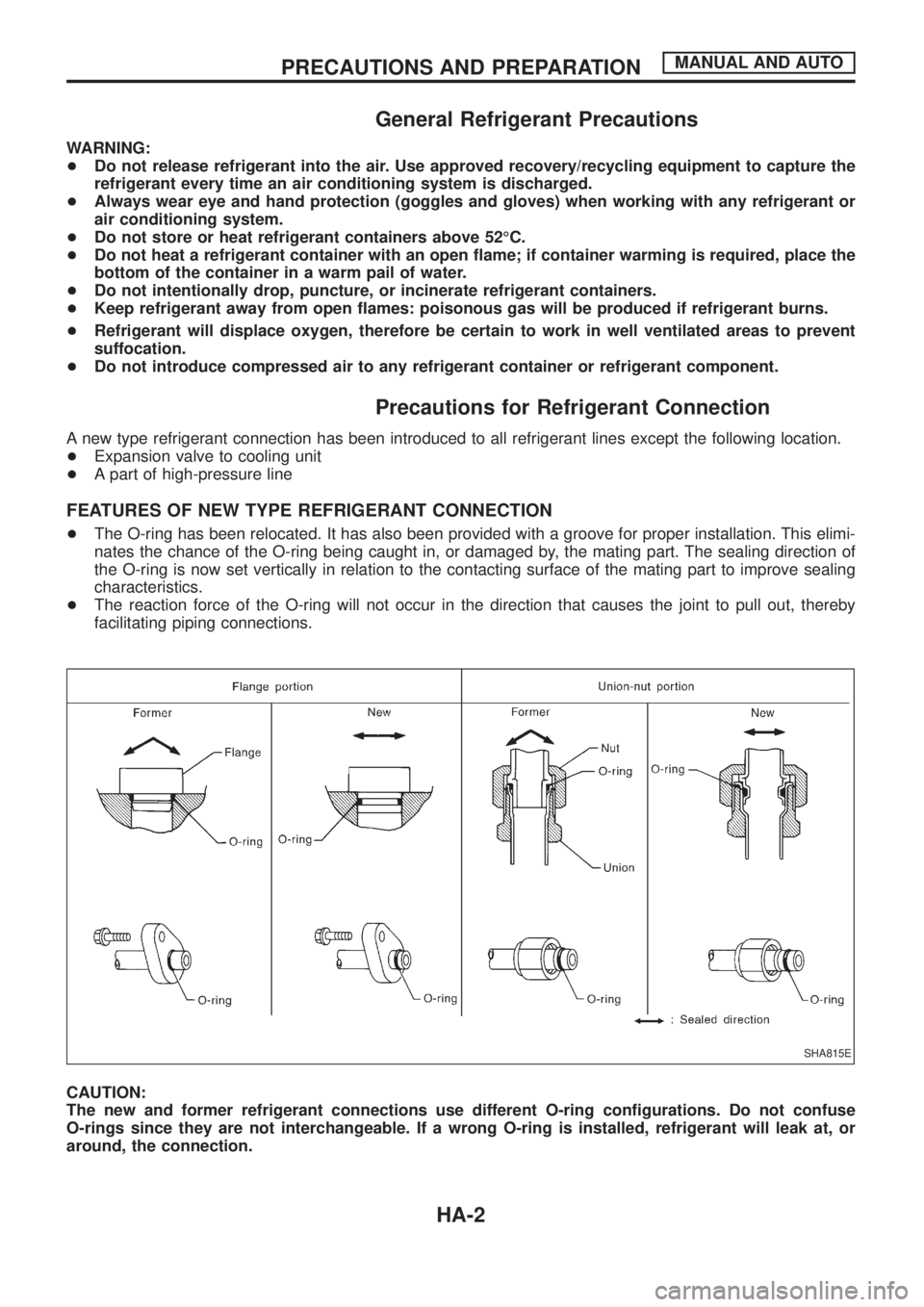
FEATURES OF NEW TYPE REFRIGERANT CONNECTION
+The O-ring has been relocated. It has also been provided with a groove for proper installation. This elimi-
nates the chance of the O-ring being caught in, or damaged by, the mating part. The sealing direction of
the O-ring is now set vertically in relation to the contacting surface of the mating part to improve sealing
characteristics.
+The reaction force of the O-ring will not occur in the direction that causes the joint to pull out, thereby
facilitating piping connections.
CAUTION:
The new and former refrigerant connections use different O-ring con®gurations. Do not confuse
O-rings since they are not interchangeable. If a wrong O-ring is installed, refrigerant will leak at, or
around, the connection.
SHA815E
PRECAUTIONS AND PREPARATIONMANUAL AND AUTO
HA-2
Page 856 of 1226
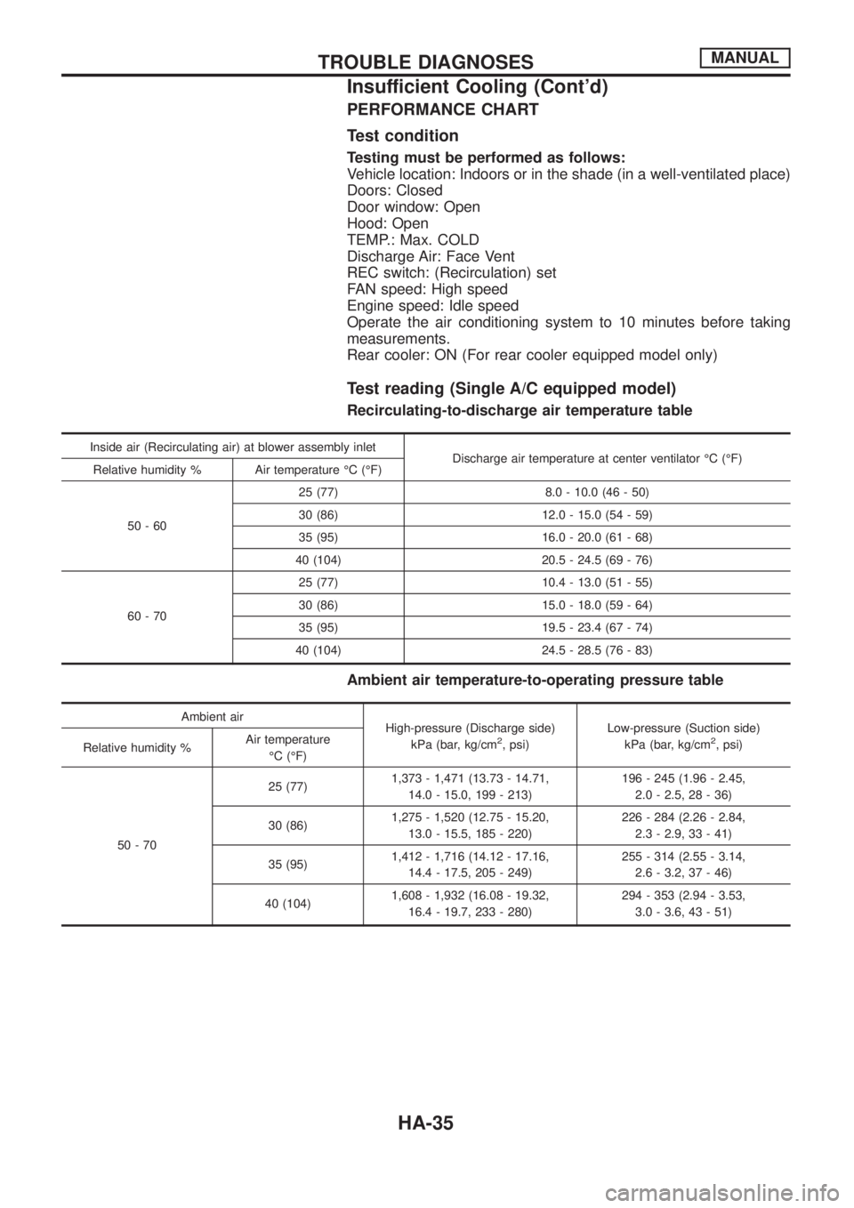
PERFORMANCE CHART
Test condition
Testing must be performed as follows:
Vehicle location: Indoors or in the shade (in a well-ventilated place)
Doors: Closed
Door window: Open
Hood: Open
TEMP.: Max. COLD
Discharge Air: Face Vent
REC switch: (Recirculation) set
FAN speed: High speed
Engine speed: Idle speed
Operate the air conditioning system to 10 minutes before taking
measurements.
Rear cooler: ON (For rear cooler equipped model only)
Test reading (Single A/C equipped model)
Recirculating-to-discharge air temperature table
Inside air (Recirculating air) at blower assembly inlet
Discharge air temperature at center ventilator ÉC (ÉF)
Relative humidity % Air temperature ÉC (ÉF)
50-6025 (77) 8.0 - 10.0 (46 - 50)
30 (86) 12.0 - 15.0 (54 - 59)
35 (95) 16.0 - 20.0 (61 - 68)
40 (104) 20.5 - 24.5 (69 - 76)
60-7025 (77) 10.4 - 13.0 (51 - 55)
30 (86) 15.0 - 18.0 (59 - 64)
35 (95) 19.5 - 23.4 (67 - 74)
40 (104) 24.5 - 28.5 (76 - 83)
Ambient air temperature-to-operating pressure table
Ambient air
High-pressure (Discharge side)
kPa (bar, kg/cm
2, psi)Low-pressure (Suction side)
kPa (bar, kg/cm2, psi)
Relative humidity %Air temperature
ÉC (ÉF)
50-7025 (77)1,373 - 1,471 (13.73 - 14.71,
14.0 - 15.0, 199 - 213)196 - 245 (1.96 - 2.45,
2.0 - 2.5, 28 - 36)
30 (86)1,275 - 1,520 (12.75 - 15.20,
13.0 - 15.5, 185 - 220)226 - 284 (2.26 - 2.84,
2.3 - 2.9, 33 - 41)
35 (95)1,412 - 1,716 (14.12 - 17.16,
14.4 - 17.5, 205 - 249)255 - 314 (2.55 - 3.14,
2.6 - 3.2, 37 - 46)
40 (104)1,608 - 1,932 (16.08 - 19.32,
16.4 - 19.7, 233 - 280)294 - 353 (2.94 - 3.53,
3.0 - 3.6, 43 - 51)
TROUBLE DIAGNOSESMANUAL
Insufficient Cooling (Cont'd)
HA-35
Page 986 of 1226
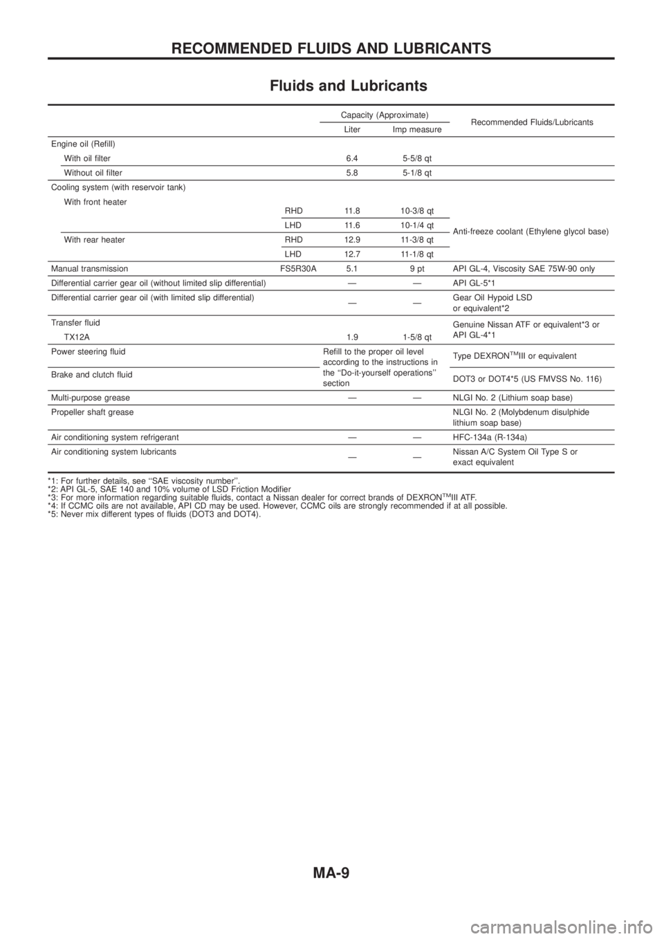
Fluids and Lubricants
Capacity (Approximate)Recommended Fluids/Lubricants
Liter Imp measure
Engine oil (Re®ll) With oil ®lter 6.4 5-5/8 qt
Without oil ®lter 5.8 5-1/8 qt
Cooling system (with reservoir tank)
Anti-freeze coolant (Ethylene glycol base)
With front heater
RHD 11.8 10-3/8 qt
LHD 11.6 10-1/4 qt
With rear heater RHD 12.9 11-3/8 qt LHD 12.7 11-1/8 qt
Manual transmission FS5R30A 5.1 9 pt API GL-4, Viscosity SAE 75W-90 only
Differential carrier gear oil (without limited slip differential) Ð Ð API GL-5*1
Differential carrier gear oil (with limited slip differential) ÐÐGearOilHypoidLSD
orequivalent*2
Transfer ¯uid Genuine Nissan ATF or equivalent*3 or
API GL-4*1
TX12A 1.9 1-5/8 qt
Power steering ¯uid Re®ll to the proper oil level according to the instructions in
the ``Do-it-yourself operations''
sectionType DEXRON
TMIII or equivalent
Brake and clutch ¯uid DOT3 or DOT4*5 (US FMVSS No. 116)
Multi-purpose grease Ð Ð NLGI No. 2 (Lithium soap base)
Propeller shaft grease NLGI No. 2 (Molybdenum disulphide
lithium soap base)
Air conditioning system refrigerant Ð Ð HFC-134a (R-134a)
Air conditioning system lubricants ÐÐNissan A/C System Oil Type S or
exact equivalent
*1: For further details, see ``SAE viscosity number''.
*2:APIGL-5,SAE140and10%volumeofLSDFrictionModi®er
*3: For more information regarding suitable ¯uids, contact a Nissan dealer for correct brands of DEXRON
TMIII ATF.
*4: If CCMC oils are not available, API CD may be used. However, CCMC oils are strongly recommended if at all possible.
*5: Never mix different types of ¯uids (DOT3 and DOT4).
RECOMMENDED FLUIDS AND LUBRICANTS
MA-9