Page 169 of 1226
Fuel Injection Timing System
SYSTEM DESCRIPTION
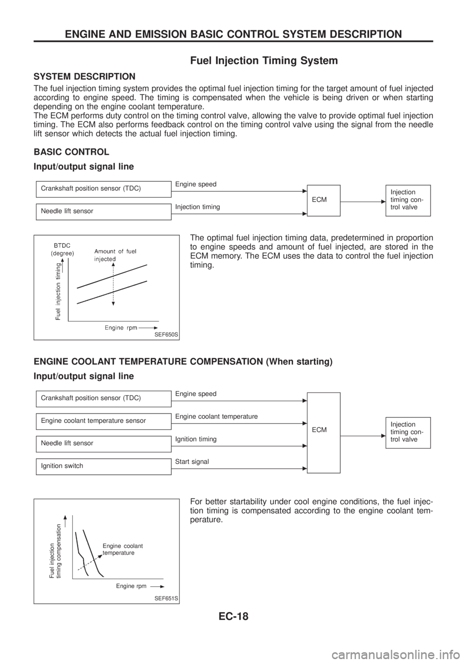
The fuel injection timing system provides the optimal fuel injection timing for the target amount of fuel injected
according to engine speed. The timing is compensated when the vehicle is being driven or when starting
depending on the engine coolant temperature.
The ECM performs duty control on the timing control valve, allowing the valve to provide optimal fuel injection
timing. The ECM also performs feedback control on the timing control valve using the signal from the needle
lift sensor which detects the actual fuel injection timing.
BASIC CONTROL
Input/output signal line
Crankshaft position sensor (TDC)cEngine speed
ECM
c
Injection
timing con-
trol valve
Needle lift sensorcInjection timing
The optimal fuel injection timing data, predetermined in proportion
to engine speeds and amount of fuel injected, are stored in the
ECM memory. The ECM uses the data to control the fuel injection
timing.
ENGINE COOLANT TEMPERATURE COMPENSATION (When starting)
Input/output signal line
Crankshaft position sensor (TDC)cEngine speed
ECM
c
Injection
timing con-
trol valveEngine coolant temperature sensorcEngine coolant temperature
Needle lift sensor
cIgnition timing
Ignition switch
cStart signal
For better startability under cool engine conditions, the fuel injec-
tion timing is compensated according to the engine coolant tem-
perature.
SEF650S
SEF651S
Fuel injection
timing compensation
Engine coolant
temperature
Engine rpm
ENGINE AND EMISSION BASIC CONTROL SYSTEM DESCRIPTION
EC-18
Page 220 of 1226
Camshaft Position Sensor (CMPS) (PUMP)
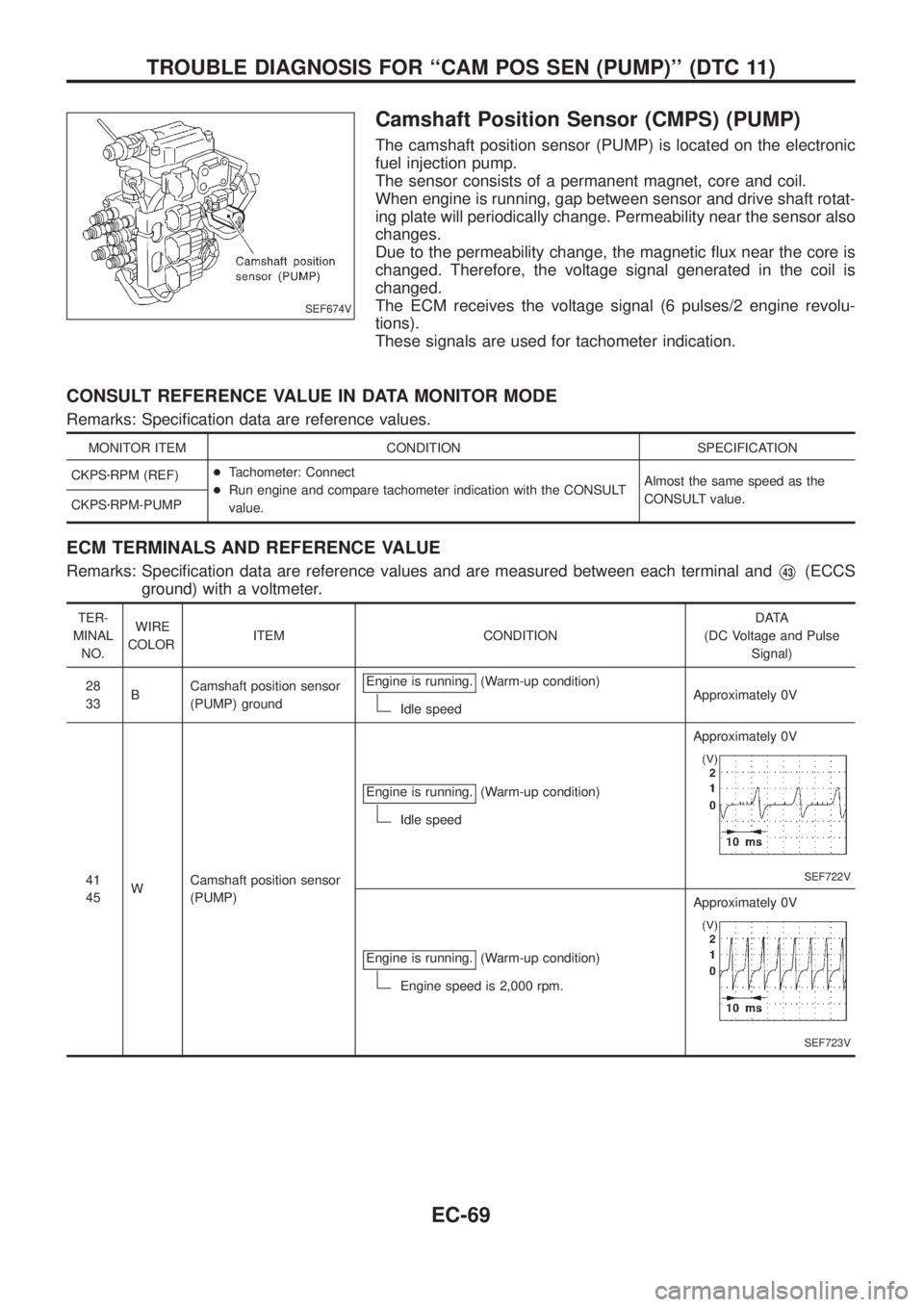
The camshaft position sensor (PUMP) is located on the electronic
fuel injection pump.
The sensor consists of a permanent magnet, core and coil.
When engine is running, gap between sensor and drive shaft rotat-
ing plate will periodically change. Permeability near the sensor also
changes.
Due to the permeability change, the magnetic ¯ux near the core is
changed. Therefore, the voltage signal generated in the coil is
changed.
The ECM receives the voltage signal (6 pulses/2 engine revolu-
tions).
These signals are used for tachometer indication.
CONSULT REFERENCE VALUE IN DATA MONITOR MODE
Remarks: Speci®cation data are reference values.
MONITOR ITEM CONDITION SPECIFICATION
CKPSzRPM (REF)+Tachometer: Connect
+Run engine and compare tachometer indication with the CONSULT
value.Almost the same speed as the
CONSULT value.
CKPSzRPM-PUMP
ECM TERMINALS AND REFERENCE VALUE
Remarks: Speci®cation data are reference values and are measured between each terminal andV43(ECCS
ground) with a voltmeter.
TER-
MINAL
NO.WIRE
COLORITEM CONDITIONDATA
(DC Voltage and Pulse
Signal)
28
33BCamshaft position sensor
(PUMP) groundEngine is running.
(Warm-up condition)
Idle speedApproximately 0V
41
45WCamshaft position sensor
(PUMP)Engine is running.
(Warm-up condition)
Idle speedApproximately 0V
SEF722V
Engine is running.(Warm-up condition)
Engine speed is 2,000 rpm.Approximately 0V
SEF723V
SEF674V
TROUBLE DIAGNOSIS FOR ``CAM POS SEN (PUMP)'' (DTC 11)
EC-69
Page 329 of 1226
Charge Air Cooler Fan Control
SYSTEM DESCRIPTION
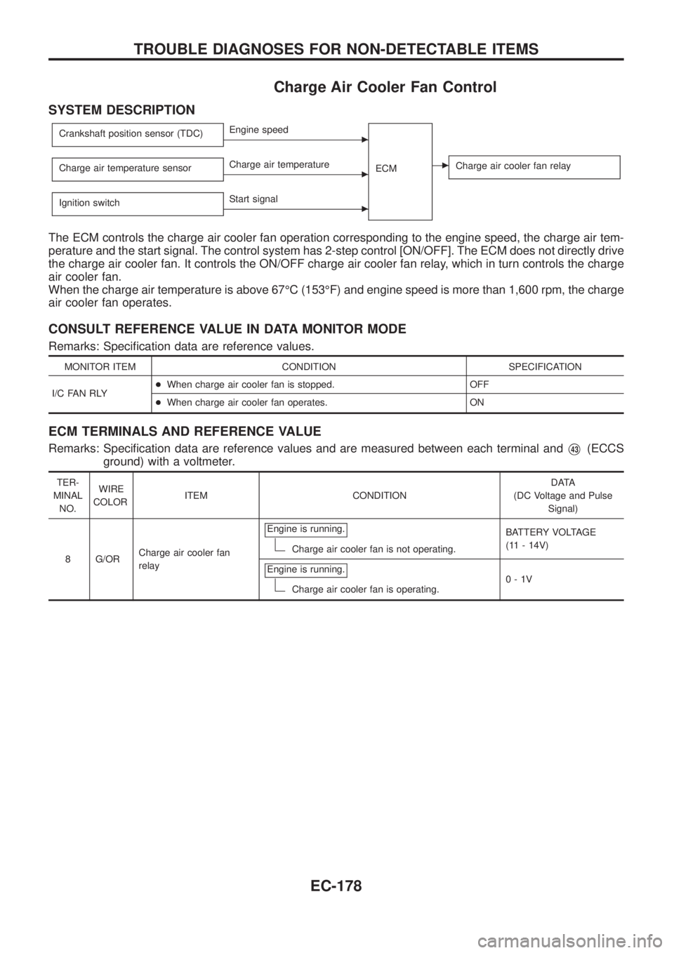
Crankshaft position sensor (TDC)cEngine speed
ECM
cCharge air cooler fan relayCharge air temperature sensorcCharge air temperature
Ignition switch
cStart signal
The ECM controls the charge air cooler fan operation corresponding to the engine speed, the charge air tem-
perature and the start signal. The control system has 2-step control [ON/OFF]. The ECM does not directly drive
the charge air cooler fan. It controls the ON/OFF charge air cooler fan relay, which in turn controls the charge
air cooler fan.
When the charge air temperature is above 67ÉC (153ÉF) and engine speed is more than 1,600 rpm, the charge
air cooler fan operates.
CONSULT REFERENCE VALUE IN DATA MONITOR MODE
Remarks: Speci®cation data are reference values.
MONITOR ITEM CONDITION SPECIFICATION
I/C FAN RLY+When charge air cooler fan is stopped. OFF
+When charge air cooler fan operates. ON
ECM TERMINALS AND REFERENCE VALUE
Remarks: Speci®cation data are reference values and are measured between each terminal andV43(ECCS
ground) with a voltmeter.
TER-
MINAL
NO.WIRE
COLORITEM CONDITIONDATA
(DC Voltage and Pulse
Signal)
8 G/ORCharge air cooler fan
relayEngine is running.
Charge air cooler fan is not operating.BATTERY VOLTAGE
(11 - 14V)
Engine is running.
Charge air cooler fan is operating.0-1V
TROUBLE DIAGNOSES FOR NON-DETECTABLE ITEMS
EC-178
Page 676 of 1226
NVH Troubleshooting Chart Ð Engine Noise
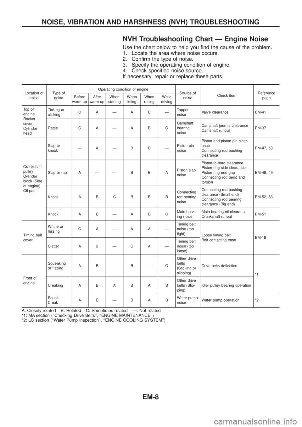
Use the chart below to help you ®nd the cause of the problem.
1. Locate the area where noise occurs.
2. Con®rm the type of noise.
3. Specify the operating condition of engine.
4. Check speci®ed noise source.
If necessary, repair or replace these parts.
Location of
noiseType of
noiseOperating condition of engine
Source of
noiseCheck itemReference
page Before
warm-upAfter
warm-upWhen
startingWhen
idlingWhen
racingWhile
driving
To p o f
engine
Rocker
cover
Cylinder
headTicking or
clickingCAÐABÐTappet
noiseValve clearance EM-41
Rattle C A Ð A B CCamshaft
bearing
noiseCamshaft journal clearance
Camshaft runoutEM-37
Crankshaft
pulley
Cylinder
block (Side
of engine)
Oil panSlap or
knockÐAÐB BÐPiston pin
noisePiston and piston pin clear-
ance
Connecting rod bushing
clearanceEM-47, 53
Slap or rap A Ð Ð B B APiston slap
noisePiston-to-bore clearance
Piston ring side clearance
Piston ring end gap
Connecting rod bend and
torsionEM-48, 49
Knock A B C B B BConnecting
rod bearing
noiseConnecting rod bushing
clearance (Small end)
Connecting rod bearing
clearance (Big end)EM-52, 53
Knock A B Ð A B CMain bear-
ing noiseMain bearing oil clearance
Crankshaft runoutEM-51
Timing belt
coverWhine or
hissingCAÐAAÐTiming belt
noise (too
tight)
Loose timing belt
Belt contacting caseEM-18
Clatter A B Ð C A ÐTiming belt
noise (too
loose)
Front of
engineSqueaking
or ®zzingABÐBÐCOther drive
belts
(Sticking or
slipping)Drive belts de¯ection
*1
CreakingABABABOther drive
belts (Slip-
ping)Idler pulley bearing operation
Squall
CreakABÐBABWater pump
noiseWater pump operation *2
A: Closely related B: Related C: Sometimes related Ð: Not related
*1: MA section (``Checking Drive Belts'', ``ENGINE MAINTENANCE'')
*2: LC section (``Water Pump Inspection'', ``ENGINE COOLING SYSTEM'')
NOISE, VIBRATION AND HARSHNESS (NVH) TROUBLESHOOTING
EM-8
Page 684 of 1226
CAUTION:
+Do not bend or twist timing belt.
+After removing timing belt, do not turn crankshaft and
camshaft separately because valves will strike piston
heads.
+Make sure that timing belt, camshaft sprocket, crankshaft
sprocket, idler pulley, injection pump pulley and belt ten-
sioner are clean and free from oil and water.
+Align white lines on timing belt with punch mark on cam-
shaft sprocket, crankshaft sprocket and injection pump
pulley.
+Installation should be carried out when engine is cold.
Removal
1. Remove radiator shroud.
2. Remove the following belts.
+Power steering drive belt
+A/C compressor drive belt
+Alternator drive belt
3. Remove cooling fan coupling and water pump pulley.
SMA767BA
TIMING BELT
EM-16
Page 688 of 1226
3. Install tensioner spring and tighten belt tensioner lock nut.
:32-40Nzm
(3.3 - 4.1 kg-m, 24 - 30 ft-lb)
4. Install front cover.
5. Install crankshaft pulley.
6. Install water pump pulley and cooling fan coupling.
7. Apply liquid gasket to the connecting surface and install the
starter motor.
Use Genuine Liquid Gasket or equivalent.
8. Install drive belts and check drive belt de¯ections by pushing
midway between pulleys.
Refer to MA section (``Checking Drive Belts'').
SMA770B
SMA015C
TIMING BELT
Installation (Cont'd)
EM-20
Page 698 of 1226
CAUTION:
+When installing sliding parts such as camshaft and oil
seal, be sure to apply new engine oil on their sliding sur-
faces.
+When tightening cylinder head bolts, apply new engine oil
to thread portions and seat surfaces of bolts.
Removal
1. Remove charge air cooler assembly.
2. Set No. 1 cylinder at BDC on its expansion stroke.
3. Drain engine coolant from drain plugs on cylinder block and
radiator.
4. Remove air cleaner and/or air duct.
5. Remove timing belt.
6. Remove rocker cover securing bolts/nuts in numerical order
shown in ®gure.
To install rocker cover, tighten bolts/nuts in reverse order of
removal. Tighten in two or three stages.
7. Remove camshaft sprocket, injection pump drive sprocket and
back cover.
8. Disconnect exhaust manifold from exhaust tube.
9. Remove intake and exhaust manifold.
To install manifolds, tighten bolts/nuts in reverse order of
removal. Tighten in two or three stages.
SEM786F
SEM711B
SEM431C
CYLINDER HEAD
EM-30
Page 710 of 1226
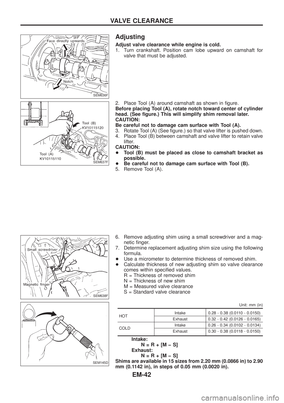
Adjusting
Adjust valve clearance while engine is cold.
1. Turn crankshaft. Position cam lobe upward on camshaft for
valve that must be adjusted.
2. Place Tool (A) around camshaft as shown in ®gure.
Before placing Tool (A), rotate notch toward center of cylinder
head. (See ®gure.) This will simplify shim removal later.
CAUTION:
Be careful not to damage cam surface with Tool (A).
3. Rotate Tool (A) (See ®gure.) so that valve lifter is pushed down.
4. Place Tool (B) between camshaft and valve lifter to retain valve
lifter.
CAUTION:
+Tool (B) must be placed as close to camshaft bracket as
possible.
+Be careful not to damage cam surface with Tool (B).
5. Remove Tool (A).
6. Remove adjusting shim using a small screwdriver and a mag-
netic ®nger.
7. Determine replacement adjusting shim size using the following
formula.
+Use a micrometer to determine thickness of removed shim.
+Calculate thickness of new adjusting shim so valve clearance
comes within speci®ed values.
R = Thickness of removed shim
N = Thickness of new shim
M = Measured valve clearance
S = Standard valve clearance
Unit: mm (in)
HOTIntake 0.28 - 0.38 (0.0110 - 0.0150)
Exhaust 0.32 - 0.42 (0.0126 - 0.0165)
COLDIntake 0.26 - 0.34 (0.0102 - 0.0134)
Exhaust 0.30 - 0.38 (0.0118 - 0.0150)
Intake:
N=R+[MþS]
Exhaust:
N=R+[MþS]
Shims are available in 15 sizes from 2.20 mm (0.0866 in) to 2.90
mm (0.1142 in), in steps of 0.05 mm (0.0020 in).
SEM636F
SEM637F
SEM638F
SEM145D
VALVE CLEARANCE
EM-42