Page 1008 of 1226

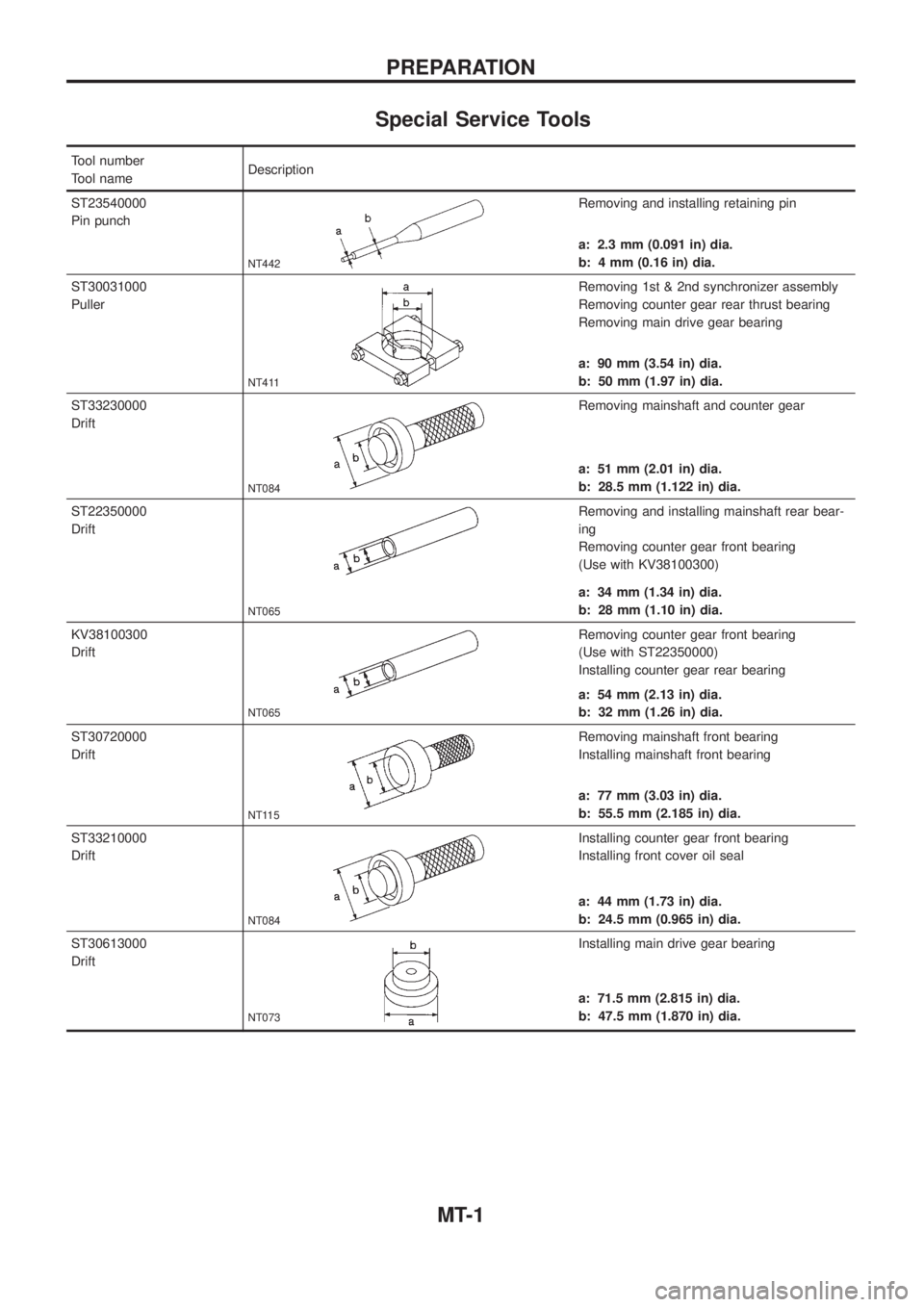
Special Service Tools
Tool number
Tool nameDescription
ST23540000
Pin punch
NT442
Removing and installing retaining pin
a: 2.3 mm (0.091 in) dia.
b: 4 mm (0.16 in) dia.
ST30031000
Puller
NT411
Removing 1st & 2nd synchronizer assembly
Removing counter gear rear thrust bearing
Removing main drive gear bearing
a: 90 mm (3.54 in) dia.
b: 50 mm (1.97 in) dia.
ST33230000
Drift
NT084
Removing mainshaft and counter gear
a: 51 mm (2.01 in) dia.
b: 28.5 mm (1.122 in) dia.
ST22350000
Drift
NT065
Removing and installing mainshaft rear bear-
ing
Removing counter gear front bearing
(Use with KV38100300)
a: 34 mm (1.34 in) dia.
b: 28 mm (1.10 in) dia.
KV38100300
Drift
NT065
Removing counter gear front bearing
(Use with ST22350000)
Installing counter gear rear bearing
a: 54 mm (2.13 in) dia.
b: 32 mm (1.26 in) dia.
ST30720000
Drift
NT115
Removing mainshaft front bearing
Installing mainshaft front bearing
a: 77 mm (3.03 in) dia.
b: 55.5 mm (2.185 in) dia.
ST33210000
Drift
NT084
Installing counter gear front bearing
Installing front cover oil seal
a: 44 mm (1.73 in) dia.
b: 24.5 mm (0.965 in) dia.
ST30613000
Drift
NT073
Installing main drive gear bearing
a: 71.5 mm (2.815 in) dia.
b: 47.5 mm (1.870 in) dia.
PREPARATION
MT-1
Page 1022 of 1226
3. Drive out retaining pin from striking lever.
4. While pulling out striking rod, remove striking lever and striking
interlock. Then remove 1st & 2nd, 3rd & 4th and reverse shift
fork.
5. Drive out retaining pin from OD shift fork.
6. Pull out OD fork rod and then remove OD shift fork.
Gear Components
1. Before removing gears and shafts, measure each gear end
play.
Gear end play:
Refer to SDS, MT-33.
+If not within speci®cation, disassemble and check contact sur-
face of gear to hub, washer, bushing, needle bearing and shaft.
2. Remove rear side components on mainshaft and counter gear.
a. Remove reverse coupling sleeve.
b. Remove mainshaft rear snap ring and counter gear rear snap
ring.
c. Remove C-ring holder and mainshaft C-rings from mainshaft.
Use punch and hammer to remove C-rings.
SMT374AA
SMT824C
SMT376A
SMT825C
SMT826C
DISASSEMBLY
Shift Control Components (Cont'd)
MT-15
Page 1026 of 1226
Shift Control Components
+Check contact surface and sliding surface for wear, scratches,
projections or other damage.
Gear Components
GEARS AND SHAFTS
+Check shafts for cracks, wear or bending.
+Check gears for excessive wear, chips or cracks.
SYNCHRONIZERS
+Check spline portion of coupling sleeves, hubs, and gears for
wear or cracks.
+Check baulk rings for cracks or deformation.
+Check shifting inserts for wear or deformation.
+Check insert springs for deformation.
+Measure wear of main drive, 1st and OD baulk rings.
Clearance between baulk ring and gear:
Refer to SDS, MT-33.
+If the clearance is smaller than the wear limit, replace baulk
ring.
SMT398A
SMT386A
SMT423A
SMT427C
SMT140
INSPECTION
MT-19
Page 1032 of 1226
b. Place dial indicator on front end of reverse idler shaft.
c. Put straightedge on front surface of OD gear case as a stop-
per of reverse idler shaft.
d. Move reverse idler shaft up and down and measure reverse
idler gear end play.
Reverse idler gear end play:
0.30 - 0.53 mm (0.0118 - 0.0209 in)
e. If not within speci®cation, replace reverse idler rear thrust
washer with the other (A or B) and check again.
7. Install mainshaft and counter gear on adapter plate and main
drive gear on mainshaft.
a. Mount adapter plate on vise and apply multi-purpose grease to
counter gear rear bearing.
b. Install mainshaft a little on mainshaft front bearing.
+To allow for installation of counter gear, do not install
mainshaft completely.
c. Install counter gear on counter gear rear bearing and install
main drive gear, pilot bearing and spacer on mainshaft.
SMT433A
SMT438A
SMT440A
SMT441A
ASSEMBLY
Gear Components (Cont'd)
MT-25
Page 1033 of 1226
+When installing counter gear into counter gear rear
bearing, push up on upper roller of counter gear rear bear-
ing with screwdriver.
d. Install mainshaft and counter gear completely by tapping rear
side of adapter plate and pulling mainshaft.
8. Install rear side components on mainshaft and counter gear.
a. Install OD gear bushing while pushing on the front of counter
gear.
b. Install OD main gear.
+Pay attention to direction of OD main gear. (B is wider than
A as shown at left.)
c. Install adapter plate with gear assembly onto transmission
case.
d. Install OD gear needle bearing and then install OD counter gear
and reverse idler shaft.
e. Install reverse cone.
SMT442A
SMT443A
SMT444AA
SMT580AB
SMT582AA
ASSEMBLY
Gear Components (Cont'd)
MT-26
Page 1039 of 1226
General Speci®cations
Applied modelRD28ETi
4WD
Transmission FS5R30A
Number of speed 5
Transmission control Floor direct
Shift pattern
Synchromesh type Warner
Gear ratio
1st 4.061
2nd 2.357
3rd 1.490
4th 1.000
OD 0.862
Reverse 4.125
Number of teeth
Mainshaft
Drive 20
1st 32
2nd 30
3rd 28
OD 23
Reverse 30
Countershaft
Drive 33
1st 13
2nd 21
3rd 31
OD 44
Reverse 12
Reverse idler gear 22
Oil capacity!(Imp pt) 5.1 (9)
Remarks2nd & 3rd double baulk ring
type synchronizer
Reverse breaking mechanism type
SERVICE DATA AND SPECIFICATIONS (SDS)
MT-32
Page 1040 of 1226

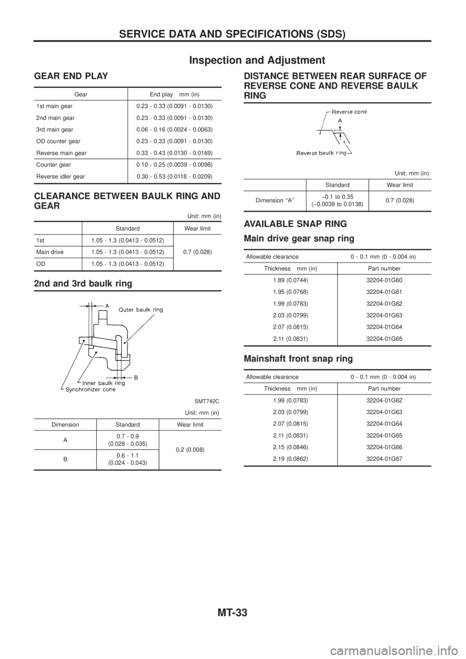
Inspection and Adjustment
GEAR END PLAY
Gear End play mm (in)
1st main gear 0.23 - 0.33 (0.0091 - 0.0130)
2nd main gear 0.23 - 0.33 (0.0091 - 0.0130)
3rd main gear 0.06 - 0.16 (0.0024 - 0.0063)
OD counter gear 0.23 - 0.33 (0.0091 - 0.0130)
Reverse main gear 0.33 - 0.43 (0.0130 - 0.0169)
Counter gear 0.10 - 0.25 (0.0039 - 0.0098)
Reverse idler gear 0.30 - 0.53 (0.0118 - 0.0209)
CLEARANCE BETWEEN BAULK RING AND
GEAR
Unit: mm (in)
Standard Wear limit
1st 1.05 - 1.3 (0.0413 - 0.0512)
0.7 (0.028) Main drive 1.05 - 1.3 (0.0413 - 0.0512)
OD 1.05 - 1.3 (0.0413 - 0.0512)
2nd and 3rd baulk ring
SMT742C
Unit: mm (in)
Dimension Standard Wear limit
A0.7 - 0.9
(0.028 - 0.035)
0.2 (0.008)
B0.6 - 1.1
(0.024 - 0.043)
DISTANCE BETWEEN REAR SURFACE OF
REVERSE CONE AND REVERSE BAULK
RING
Unit: mm (in)
Standard Wear limit
Dimension ``A''þ0.1 to 0.35
(þ0.0039 to 0.0138)0.7 (0.028)
AVAILABLE SNAP RING
Main drive gear snap ring
Allowable clearance 0 - 0.1 mm (0 - 0.004 in)
Thickness mm (in) Part number
1.89 (0.0744) 32204-01G60
1.95 (0.0768) 32204-01G61
1.99 (0.0783) 32204-01G62
2.03 (0.0799) 32204-01G63
2.07 (0.0815) 32204-01G64
2.11 (0.0831) 32204-01G65
Mainshaft front snap ring
Allowable clearance 0 - 0.1 mm (0 - 0.004 in)
Thickness mm (in) Part number
1.99 (0.0783) 32204-01G62
2.03 (0.0799) 32204-01G63
2.07 (0.0815) 32204-01G64
2.11 (0.0831) 32204-01G65
2.15 (0.0846) 32204-01G66
2.19 (0.0862) 32204-01G67
SERVICE DATA AND SPECIFICATIONS (SDS)
MT-33
Page 1042 of 1226

PROPELLER SHAFT &
DIFFERENTIAL CARRIER
SECTION
PD
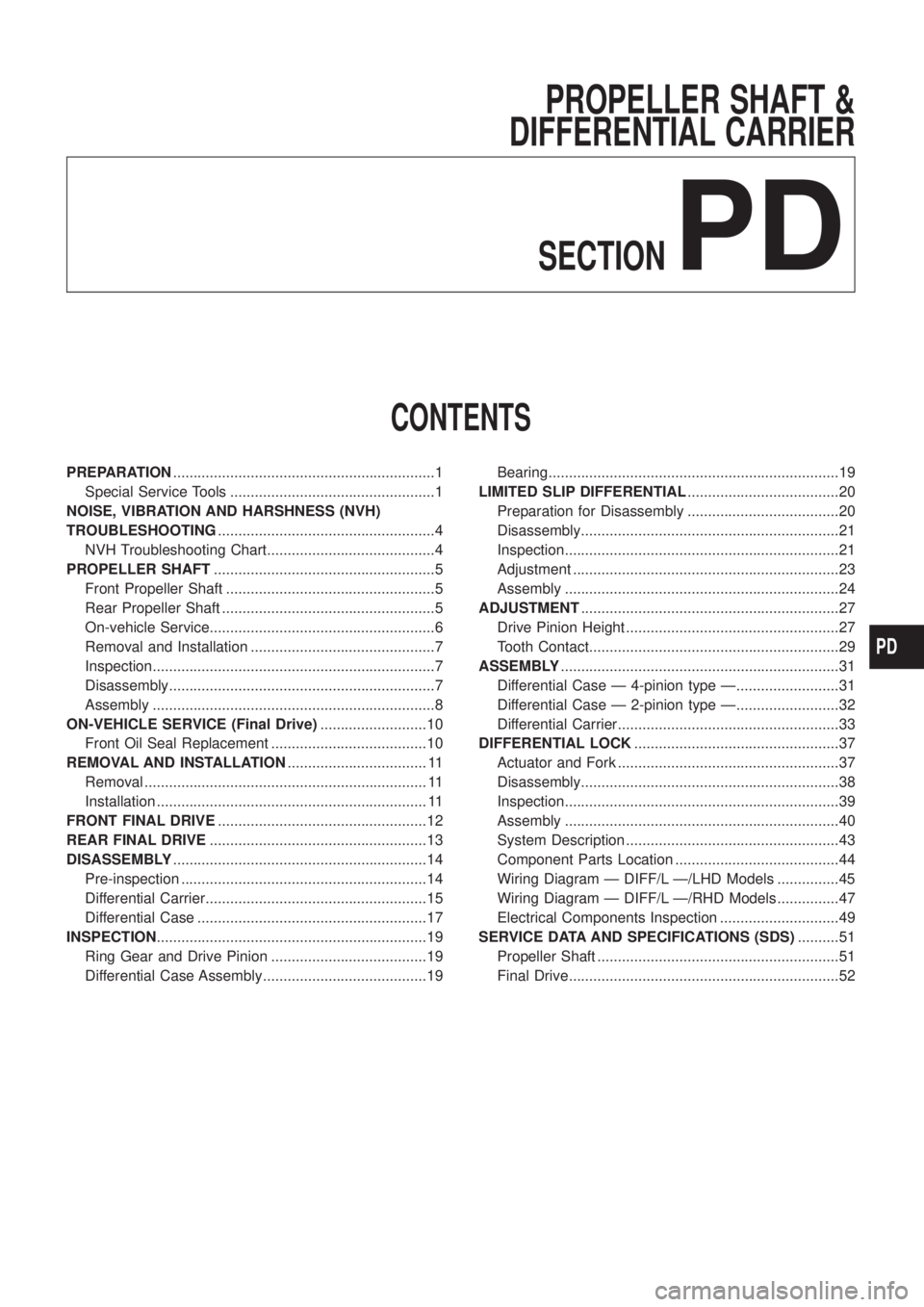
CONTENTS
PREPARATION................................................................1
Special Service Tools ..................................................1
NOISE, VIBRATION AND HARSHNESS (NVH)
TROUBLESHOOTING.....................................................4
NVH Troubleshooting Chart.........................................4
PROPELLER SHAFT......................................................5
Front Propeller Shaft ...................................................5
Rear Propeller Shaft ....................................................5
On-vehicle Service.......................................................6
Removal and Installation .............................................7
Inspection.....................................................................7
Disassembly.................................................................7
Assembly .....................................................................8
ON-VEHICLE SERVICE (Final Drive)..........................10
Front Oil Seal Replacement ......................................10
REMOVAL AND INSTALLATION.................................. 11
Removal ..................................................................... 11
Installation .................................................................. 11
FRONT FINAL DRIVE...................................................12
REAR FINAL DRIVE.....................................................13
DISASSEMBLY..............................................................14
Pre-inspection ............................................................14
Differential Carrier......................................................15
Differential Case ........................................................17
INSPECTION..................................................................19
Ring Gear and Drive Pinion ......................................19
Differential Case Assembly........................................19Bearing.......................................................................19
LIMITED SLIP DIFFERENTIAL.....................................20
Preparation for Disassembly .....................................20
Disassembly...............................................................21
Inspection...................................................................21
Adjustment .................................................................23
Assembly ...................................................................24
ADJUSTMENT...............................................................27
Drive Pinion Height ....................................................27
Tooth Contact.............................................................29
ASSEMBLY....................................................................31
Differential Case Ð 4-pinion type Ð.........................31
Differential Case Ð 2-pinion type Ð.........................32
Differential Carrier......................................................33
DIFFERENTIAL LOCK..................................................37
Actuator and Fork ......................................................37
Disassembly...............................................................38
Inspection...................................................................39
Assembly ...................................................................40
System Description ....................................................43
Component Parts Location ........................................44
Wiring Diagram Ð DIFF/L Ð/LHD Models ...............45
Wiring Diagram Ð DIFF/L Ð/RHD Models ...............47
Electrical Components Inspection .............................49
SERVICE DATA AND SPECIFICATIONS (SDS)..........51
Propeller Shaft ...........................................................51
Final Drive..................................................................52
PD