2006 NISSAN PATROL fuel
[x] Cancel search: fuelPage 1 of 1226

Edition: February 1998
Release: February 1998 (01)
Publication No.: SM8E-0Y61E0E
Reference No.: 7711346063GENERAL INFORMATIONGI
MAINTENANCEMA
ENGINE MECHANICALEM
ENGINE LUBRICATION &
COOLING SYSTEMSLC
ENGINE CONTROL SYSTEMEC
ACCELERATOR CONTROL,
FUEL & EXHAUST SYSTEMFE
CLUTCHCL
MANUAL TRANSMISSIONMT
AUTOMATIC TRANSMISSIONAT
TRANSFERTF
PROPELLER SHAFT &
DIFFERENTIAL CARRIERPD
FRONT AXLE & FRONT SUSPENSIONFA
REAR AXLE & REAR SUSPENSIONRA
BRAKE SYSTEMBR
STEERING SYSTEMST
RESTRAINT SYSTEMRS
BODY & TRIMBT
HEATER & AIR CONDITIONERHA
ELECTRICAL SYSTEMEL
ALPHABETICAL INDEXIDX
PATROL GR
MODEL Y61 SERIES
NISSAN EUROPE S.A.S.
1998 NISSAN EUROPE S.A.S.
Produced in The Netherlands
Not to be reproduced in whole or in part
without the prior written permission of
Nissan Europe S.A.S., Paris, France.
QUICK REFERENCE INDEX
Page 11 of 1226

1. Ensure vehicle is unladen condition*.* Fuel, radiator coolant and engine oil full. Spare tire, jack,hand tools and mats in designated positions.
2. Have a driver sit in the driver's seat and one person sit on the rear end. Then have the person on the rear end slowly get off
the vehicle. This is necessary to stabilize suspension de¯ec-
tion.
3. Gradually depress brake pedal and attach a lever to the stop- per bolt, then adjust length ``L'' as follows:Length ``L'': Approx. 175.2 - 178.2 mm (6.90 - 7.02 in)
4. Remove front LH tire.
5. Connect tool to air bleeders on front LH brake caliper and rear LH or RH brake wheel cylinder.
6. Install front LH tire.
Before installing front LH tire, con®rm the tool is not touching
the front LH wheel.
7. Bleed air from Tool.
8. Raise front brake pressure to 4,904 kPa (49.0 bar, 50 kg/cm
2,
711 psi) and 9,807 kPa (98.1 bar, 100 kg/cm2, 1,422 psi) and
check rear brake pressure. Rear brake pressure: Refer to table on next page.
SBR287E
SBR822BA
SBR823BA
SBR377D
BRAKE HYDRAULIC LINE/CONTROL VALVE
Load Sensing Valve (Cont'd)
BR-7
Page 84 of 1226
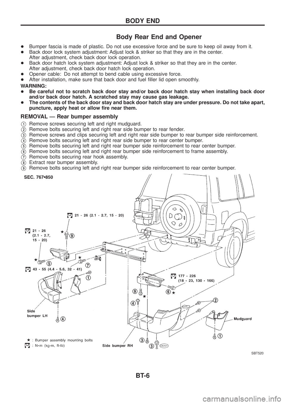
Body Rear End and Opener
+Bumper fascia is made of plastic. Do not use excessive force and be sure to keep oil away from it.
+Back door lock system adjustment: Adjust lock & striker so that they are in the center.
After adjustment, check back door lock operation.
+Back door hatch lock system adjustment: Adjust lock & striker so that they are in the center.
After adjustment, check back door hatch lock operation.
+Opener cable: Do not attempt to bend cable using excessive force.
+After installation, make sure that back door and fuel ®ller lid open smoothly.
WARNING:
+Be careful not to scratch back door stay and/or back door hatch stay when installing back door
and/or back door hatch. A scratched stay may cause gas leakage.
+The contents of the back door stay and back door hatch stay are under pressure. Do not take apart,
puncture, apply heat or allow ®re near them.
REMOVAL Ð Rear bumper assembly
V1Remove screws securing left and right mudguard.
V2Remove bolts securing left and right rear side bumper to rear fender.
V3Remove screws and clips securing left and right rear side bumper to rear bumper side reinforcement.
V4Remove bolts securing left and right rear side bumper to rear center bumper.
V5Remove bolts securing left and right rear bumper side reinforcement to rear center bumper.
V6Remove bolts securing left and right rear bumper side reinforcement to frame assembly.
V7Remove bolts securing rear hook assembly.
V8Extract rear bumper assembly.
V9Remove bolts securing left and right rear bumper side reinforcement to rear center bumper.
SBT520
BODY END
BT-6
Page 150 of 1226
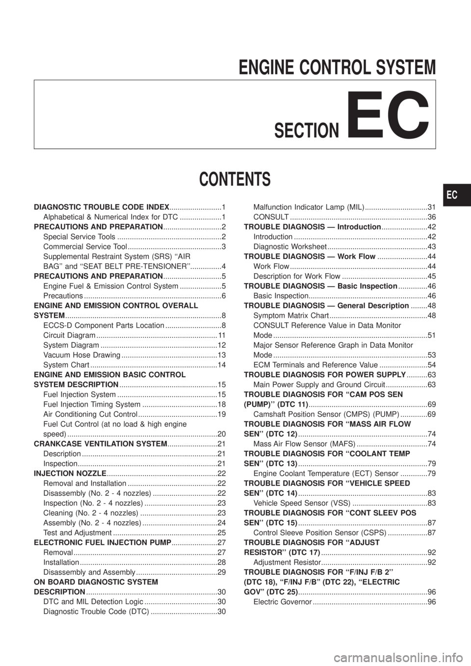
ENGINE CONTROL SYSTEMSECTION
EC
CONTENTS
DIAGNOSTIC TROUBLE CODE INDEX .........................1
Alphabetical & Numerical Index for DTC ....................1
PRECAUTIONS AND PREPARATION ............................2
Special Service Tools ..................................................2
Commercial Service Tool .............................................3
Supplemental Restraint System (SRS) ``AIR
BAG'' and ``SEAT BELT PRE-TENSIONER''...............4
PRECAUTIONS AND PREPARATION ............................5
Engine Fuel & Emission Control System ....................5
Precautions ..................................................................6
ENGINE AND EMISSION CONTROL OVERALL
SYSTEM ........................................................................\
...8
ECCS-D Component Parts Location ...........................8
Circuit Diagram .......................................................... 11
System Diagram ........................................................12
Vacuum Hose Drawing ..............................................13
System Chart .............................................................14
ENGINE AND EMISSION BASIC CONTROL
SYSTEM DESCRIPTION ...............................................15
Fuel Injection System ................................................15
Fuel Injection Timing System ....................................18
Air Conditioning Cut Control ......................................19
Fuel Cut Control (at no load & high engine
speed) ........................................................................\
20
CRANKCASE VENTILATION SYSTEM ........................21
Description .................................................................21
Inspection...................................................................21
INJECTION NOZZLE .....................................................22
Removal and Installation ...........................................22
Disassembly (No. 2 - 4 nozzles) ...............................22
Inspection (No. 2 - 4 nozzles) ...................................23
Cleaning (No. 2 - 4 nozzles) .....................................23
Assembly (No. 2 - 4 nozzles) ....................................24
Test and Adjustment ..................................................25
ELECTRONIC FUEL INJECTION PUMP ......................27
Removal .....................................................................27
Installation ..................................................................28
Disassembly and Assembly .......................................29
ON BOARD DIAGNOSTIC SYSTEM
DESCRIPTION ...............................................................30
DTC and MIL Detection Logic ...................................30
Diagnostic Trouble Code (DTC) ................................30 Malfunction Indicator Lamp (MIL) ..............................31
CONSULT ..................................................................36
TROUBLE DIAGNOSIS Ð Introduction ......................42
Introduction ................................................................42
Diagnostic Worksheet ................................................43
TROUBLE DIAGNOSIS Ð Work Flow ........................44
Work Flow ..................................................................44
Description for Work Flow .........................................45
TROUBLE DIAGNOSIS Ð Basic Inspection ..............46
Basic Inspection.........................................................46
TROUBLE DIAGNOSIS Ð General Description ........48
Symptom Matrix Chart ...............................................48
CONSULT Reference Value in Data Monitor
Mode ........................................................................\
..51
Major Sensor Reference Graph in Data Monitor
Mode ........................................................................\
..53
ECM Terminals and Reference Value .......................54
TROUBLEDIAGNOSISFORPOWERSUPPLY ..........63
MainPowerSupplyandGroundCircuit....................63
TROUBLE DIAGNOSIS FOR ``CAM POS SEN
(PUMP)''(DTC11) .........................................................69
CamshaftPositionSensor(CMPS)(PUMP).............69
TROUBLEDIAGNOSISFOR``MASSAIRFLOW
SEN''(DTC12) ..............................................................74
MassAirFlowSensor(MAFS)..................................74
TROUBLEDIAGNOSISFOR``COOLANTTEMP
SEN''(DTC13) ..............................................................79
EngineCoolantTemperature(ECT)Sensor.............79
TROUBLEDIAGNOSISFOR``VEHICLESPEED
SEN''(DTC14) ..............................................................83
VehicleSpeedSensor(VSS)....................................83
TROUBLEDIAGNOSISFOR``CONTSLEEVPOS
SEN''(DTC15) ..............................................................87
ControlSleevePositionSensor(CSPS)...................87
TROUBLEDIAGNOSISFOR``ADJUST
RESISTOR''(DTC17) ...................................................92
AdjustmentResistor...................................................92
TROUBLEDIAGNOSISFOR``F/INJF/B2''
(DTC18),``F/INJF/B''(DTC22),``ELECTRIC
GOV''(DTC25) ..............................................................96
ElectricGovernor.......................................................96
EC
Page 151 of 1226
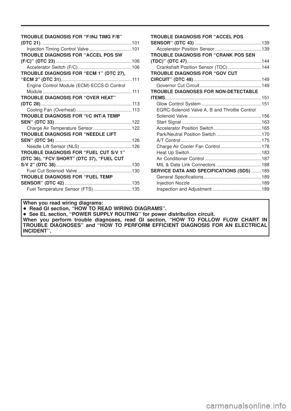
TROUBLEDIAGNOSISFOR``F/INJTIMGF/B''
(DTC21).......................................................................101
InjectionTimingControlValve.................................101
TROUBLEDIAGNOSISFOR``ACCELPOSSW
(F/C)''(DTC23) ...........................................................106
AcceleratorSwitch(F/C)..........................................106
TROUBLEDIAGNOSISFOR``ECM1''(DTC27),
``ECM2''(DTC31) .......................................................111
EngineControlModule(ECM)-ECCS-DControl
Module.....................................................................111
TROUBLEDIAGNOSISFOR``OVERHEAT''
(DTC28) .......................................................................113
CoolingFan(Overheat)...........................................113
TROUBLEDIAGNOSISFOR``I/CINT/ATEMP
SEN''(DTC33) ............................................................122
ChargeAirTemperatureSensor..............................122
TROUBLEDIAGNOSISFOR``NEEDLELIFT
SEN''(DTC34) ............................................................126
NeedleLiftSensor(NLS)........................................126
TROUBLE DIAGNOSIS FOR ``FUEL CUT S/V 1''
(DTC 36), ``FCV SHORT'' (DTC 37), ``FUEL CUT
S/V2''(DTC38) ...........................................................130
FuelCutSolenoidValve..........................................130
TROUBLE DIAGNOSIS FOR ``FUEL TEMP
SENSOR''(DTC42) ....................................................135
FuelTemperatureSensor(FTS)..............................135 TROUBLE DIAGNOSIS FOR ``ACCEL POS
SENSOR''(DTC43)
....................................................139
AcceleratorPositionSensor....................................139
TROUBLE DIAGNOSIS FOR ``CRANK POS SEN
(TDC)''(DTC47) ..........................................................144
CrankshaftPositionSensor(TDC)..........................144
TROUBLEDIAGNOSISFOR``GOVCUT
CIRCUIT''(DTC48) .....................................................149
GovernorCutCircuit................................................149
TROUBLEDIAGNOSESFORNON-DETECTABLE
ITEMS ........................................................................\
...151
GlowControlSystem...............................................151
EGRC-SolenoidValveA,BandThrottleControl
SolenoidValve.........................................................156
StartSignal..............................................................163
AcceleratorPositionSwitch.....................................165
Park/NeutralPositionSwitch...................................170
A/TControl...............................................................175
ChargeAirCoolerFanControl................................178
HeatUpSwitch........................................................183
AirConditionerControl............................................187
MIL&DataLinkConnectors...................................188
SERVICEDATAANDSPECIFICATIONS(SDS) ........189
GeneralSpeci®cations.............................................189
InjectionNozzle.......................................................189
InspectionandAdjustment......................................189
When you read wiring diagrams:
+ Read GI section, ``HOW TO READ WIRING DIAGRAMS''.
+ See EL section, ``POWER SUPPLY ROUTING'' for power distribution circuit.
When you perform trouble diagnoses, read GI section, ``HOW TO FOLLOW FLOW CHART IN
TROUBLE DIAGNOSES'' and ``HOW TO PERFORM EFFICIENT DIAGNOSIS FOR AN ELECTRICAL
INCIDENT''.
Page 152 of 1226
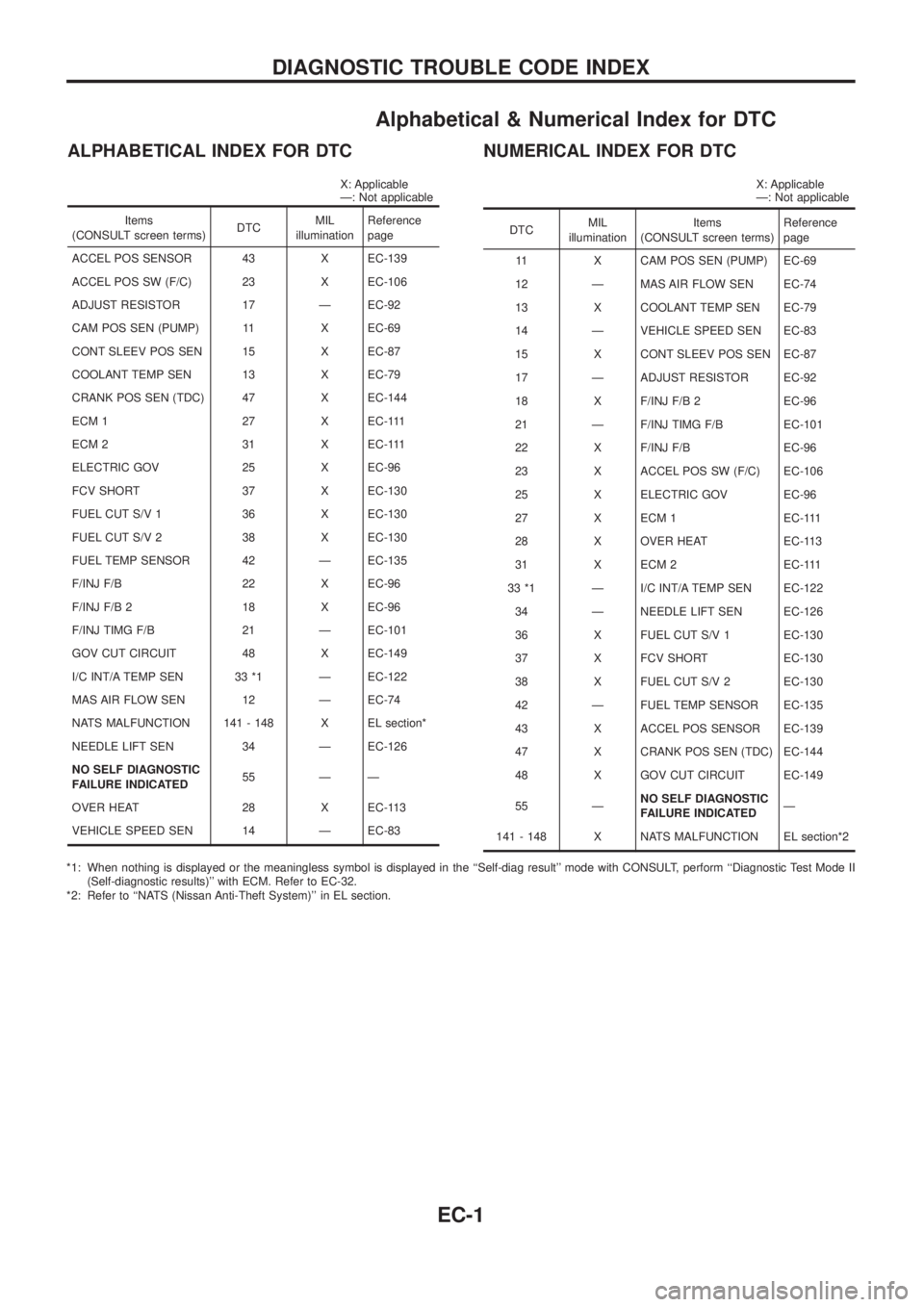
Alphabetical & Numerical Index for DTC
ALPHABETICAL INDEX FOR DTC
X: Applicable
Ð: Not applicable
Items
(CONSULT screen terms) DTCMIL
illumination Reference
page
ACCEL POS SENSOR 43 X EC-139
ACCEL POS SW (F/C) 23 X EC-106
ADJUST RESISTOR 17 Ð EC-92
CAM POS SEN (PUMP) 11 X EC-69
CONT SLEEV POS SEN 15 X EC-87
COOLANT TEMP SEN 13 X EC-79
CRANK POS SEN (TDC) 47 X EC-144
ECM 1 27 X EC-111
ECM 2 31 X EC-111
ELECTRIC GOV 25 X EC-96
FCV SHORT 37 X EC-130
FUEL CUT S/V 1 36 X EC-130
FUEL CUT S/V 2 38 X EC-130
FUEL TEMP SENSOR 42 Ð EC-135
F/INJ F/B 22 X EC-96
F/INJ F/B 2 18 X EC-96
F/INJ TIMG F/B 21 Ð EC-101
GOV CUT CIRCUIT 48 X EC-149
I/C INT/A TEMP SEN 33 *1 Ð EC-122
MAS AIR FLOW SEN 12 Ð EC-74
NATS MALFUNCTION 141 - 148 X EL section*
NEEDLE LIFT SEN 34 Ð EC-126
NO SELF DIAGNOSTIC
FAILURE INDICATED 55 Ð Ð
OVER HEAT 28 X EC-113
VEHICLE SPEED SEN 14 Ð EC-83
NUMERICAL INDEX FOR DTC
X: Applicable
Ð: Not applicable
DTC MIL
illumination Items
(CONSULT screen terms) Reference
page
11 X CAM POS SEN (PUMP) EC-69
12 Ð MAS AIR FLOW SEN EC-74
13 X COOLANT TEMP SEN EC-79
14 Ð VEHICLE SPEED SEN EC-83
15 X CONT SLEEV POS SEN EC-87
17 Ð ADJUST RESISTOR EC-92
18 X F/INJ F/B 2 EC-96
21 Ð F/INJ TIMG F/B EC-101
22 X F/INJ F/B EC-96
23 X ACCEL POS SW (F/C) EC-106
25 X ELECTRIC GOV EC-96
27 X ECM 1 EC-111
28 X OVER HEAT EC-113
31 X ECM 2 EC-111
33 *1 Ð I/C INT/A TEMP SEN EC-122 34 Ð NEEDLE LIFT SEN EC-126
36 X FUEL CUT S/V 1 EC-130
37 X FCV SHORT EC-130
38 X FUEL CUT S/V 2 EC-130
42 Ð FUEL TEMP SENSOR EC-135
43 X ACCEL POS SENSOR EC-139
47 X CRANK POS SEN (TDC) EC-144
48 X GOV CUT CIRCUIT EC-149
55 Ð NO SELF DIAGNOSTIC
FAILURE INDICATED Ð
141 - 148 X NATS MALFUNCTION EL section*2
*1: When nothing is displayed or the meaningless symbol is displayed in the ``Self-diag result'' mode with CONSULT, perform ``Diagnostic Test Mode II (Self-diagnostic results)'' with ECM. Refer to EC-32.
*2: Refer to ``NATS (Nissan Anti-Theft System)'' in EL section.
DIAGNOSTIC TROUBLE CODE INDEX
EC-1
Page 154 of 1226
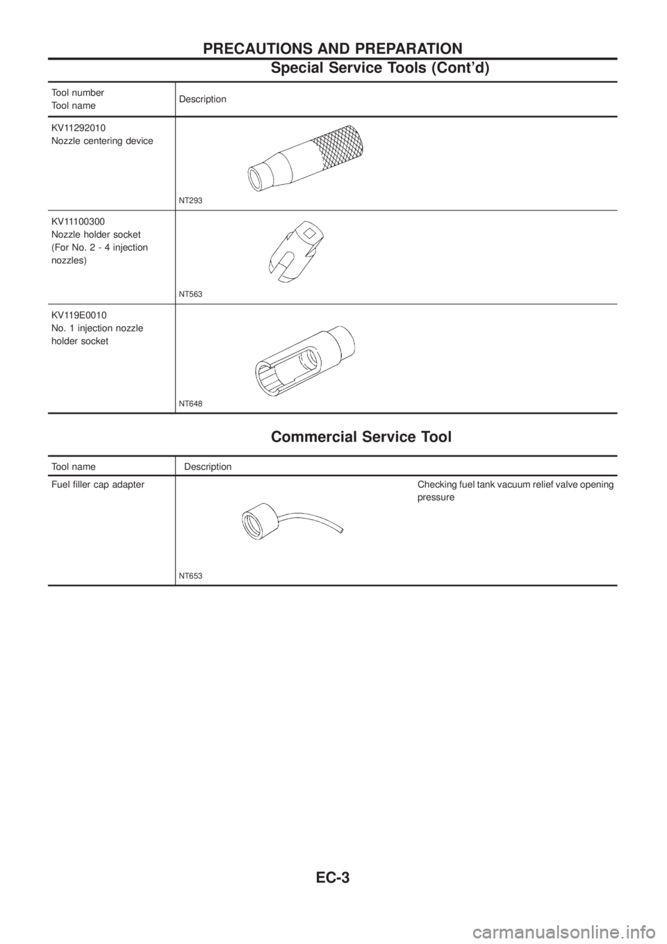
Tool number
Tool nameDescription
KV11292010
Nozzle centering device
NT293
KV11100300
Nozzle holder socket
(For No.2-4injection
nozzles)
NT563
KV119E0010
No. 1 injection nozzle
holder socket
NT648
Commercial Service Tool
Tool name Description
Fuel ®ller cap adapter
NT653
Checking fuel tank vacuum relief valve opening
pressure
PRECAUTIONS AND PREPARATION
Special Service Tools (Cont'd)
EC-3
Page 156 of 1226
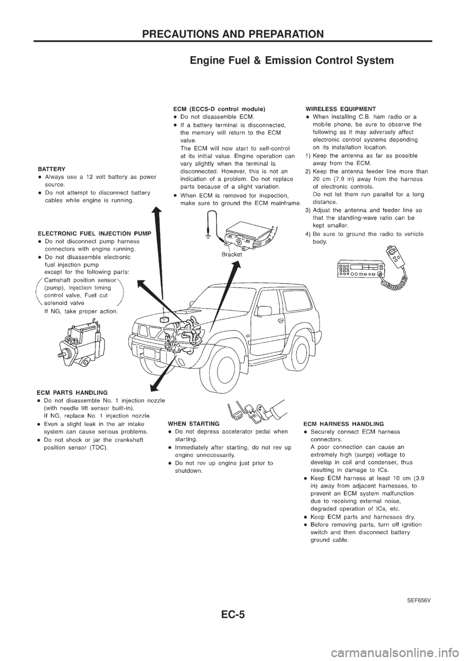
Engine Fuel & Emission Control System
SEF656V
PRECAUTIONS AND PREPARATION
EC-5