Page 994 of 1226
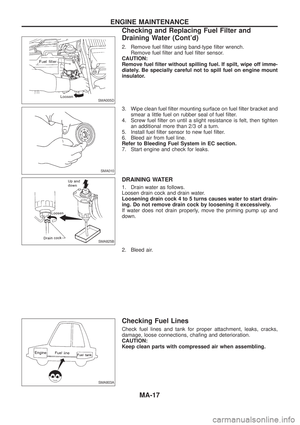
2. Remove fuel ®lter using band-type ®lter wrench.
Remove fuel ®lter and fuel ®lter sensor.
CAUTION:
Remove fuel ®lter without spilling fuel. If spilt, wipe off imme-
diately. Be specially careful not to spill fuel on engine mount
insulator.
3. Wipe clean fuel ®lter mounting surface on fuel ®lter bracket and
smear a little fuel on rubber seal of fuel ®lter.
4. Screw fuel ®lter on until a slight resistance is felt, then tighten
an additional more than 2/3 of a turn.
5. Install fuel ®lter sensor to new fuel ®lter.
6. Bleed air from fuel line.
Refer to Bleeding Fuel System in EC section.
7. Start engine and check for leaks.
DRAINING WATER
1. Drain water as follows.
Loosen drain cock and drain water.
Loosening drain cock 4 to 5 turns causes water to start drain-
ing. Do not remove drain cock by loosening it excessively.
If water does not drain properly, move the priming pump up and
down.
2. Bleed air.
Checking Fuel Lines
Check fuel lines and tank for proper attachment, leaks, cracks,
damage, loose connections, cha®ng and deterioration.
CAUTION:
Keep clean parts with compressed air when assembling.
SMA005D
SMA010
SMA825B
SMA803A
ENGINE MAINTENANCE
Checking and Replacing Fuel Filter and
Draining Water (Cont'd)
MA-17
Page 995 of 1226
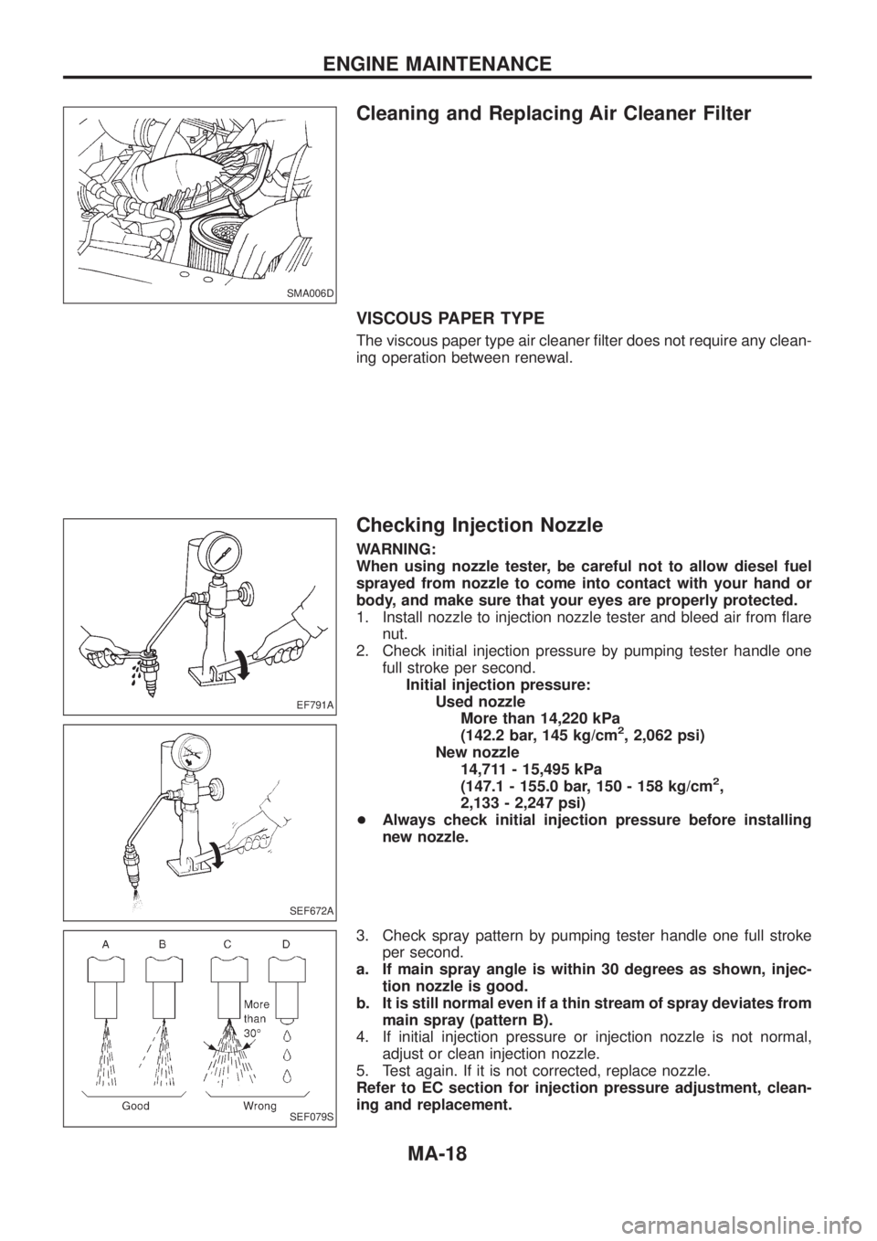
Cleaning and Replacing Air Cleaner Filter
VISCOUS PAPER TYPE
The viscous paper type air cleaner ®lter does not require any clean-
ing operation between renewal.
Checking Injection Nozzle
WARNING:
When using nozzle tester, be careful not to allow diesel fuel
sprayed from nozzle to come into contact with your hand or
body, and make sure that your eyes are properly protected.
1. Install nozzle to injection nozzle tester and bleed air from ¯are
nut.
2. Check initial injection pressure by pumping tester handle one
full stroke per second.
Initial injection pressure:
Used nozzle
More than 14,220 kPa
(142.2 bar, 145 kg/cm
2, 2,062 psi)
New nozzle
14,711 - 15,495 kPa
(147.1 - 155.0 bar, 150 - 158 kg/cm
2,
2,133 - 2,247 psi)
+Always check initial injection pressure before installing
new nozzle.
3. Check spray pattern by pumping tester handle one full stroke
per second.
a. If main spray angle is within 30 degrees as shown, injec-
tion nozzle is good.
b. It is still normal even if a thin stream of spray deviates from
main spray (pattern B).
4. If initial injection pressure or injection nozzle is not normal,
adjust or clean injection nozzle.
5. Test again. If it is not corrected, replace nozzle.
Refer to EC section for injection pressure adjustment, clean-
ing and replacement.
SMA006D
EF791A
SEF672A
SEF079S
ENGINE MAINTENANCE
MA-18
Page 996 of 1226
6. Install all injection nozzles with Tool and securely connect fuel
spill tube and delivery tubes.
7. Bleed air from fuel system and check for fuel leakage with
engine running.
Injection nozzle to cylinder head:
:59-69Nzm (6.0 - 7.0 kg-m, 43 - 51 ft-lb)
Spill tube nut:
:39-49Nzm (4.0 - 5.0 kg-m, 29 - 36 ft-lb)
Injection tube:
:20-25Nzm (2.2 - 2.5 kg-m, 16 - 18 ft-lb)
Checking Idle Speed
Inspection should be carried out with gears in ``Neutral'' and
with air conditioner and other electrical loads off.
1. Warm up engine until engine coolant temperature indicator
points to the middle of gauge.
2. Attach a diesel tachotester's pick-up to No. 1 fuel injection tube.
3. Race engine two or three times and check idle speed.
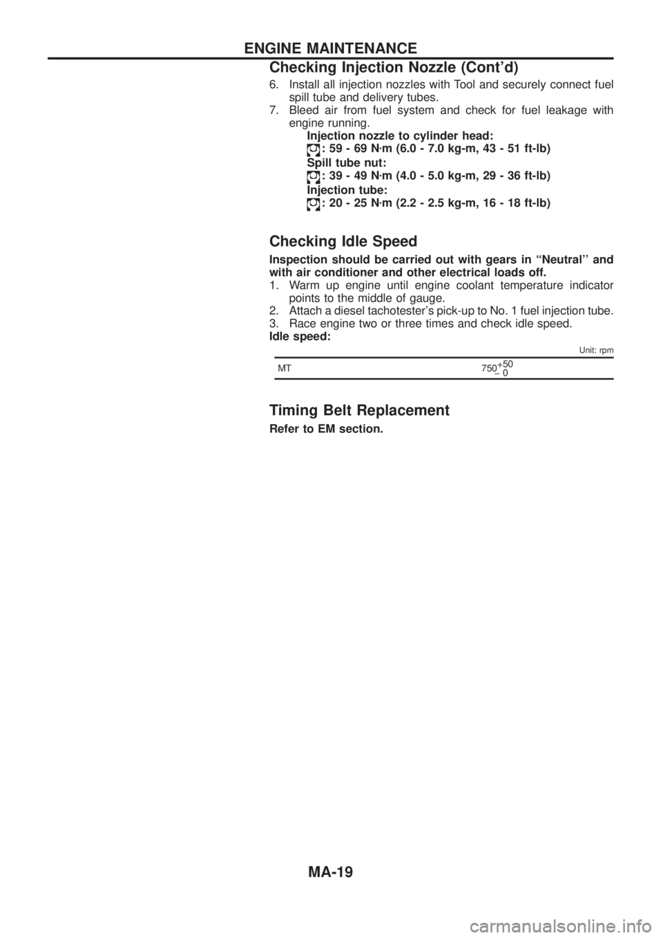
Idle speed:
Unit: rpm
MT 750+50
þ0
Timing Belt Replacement
Refer to EM section.
ENGINE MAINTENANCE
Checking Injection Nozzle (Cont'd)
MA-19
Page 1005 of 1226
Checking Body Corrosion
Visually check the body sheet metal panel for corrosion, paint damage (scratches, chipping, rubbing, etc.) or
damage to the anti-corrosion materials. In particular, check the following locations.
Hemmed portion
Hood front end, door lower end, trunk lid rear end, etc.
Panel joint
Side sill of rear fender and center pillar, rear wheel housing of rear fender, around strut tower in engine
compartment, etc.
Panel edge
Trunk lid opening, sunroof opening, fender wheelarch ¯ange, fuel ®ller lid ¯ange, around holes in panel, etc.
Parts contact
Waist molding, windshield molding, bumper, etc.
Protectors
Damage or condition of mudguard, fender protector, chipping protector, etc.
Anti-corrosion materials
Damage or separation of anti-corrosion materials under the body.
Drain holes
Condition of drain holes at door and side sill.
When repairing corroded areas, refer to the Corrosion Repair Manual.
CHASSIS AND BODY MAINTENANCE
MA-28
Page 1097 of 1226
Precautions
+When installing rubber parts, ®nal tightening must be car-
ried out under unladen condition* with tires on ground.
*: Fuel, radiator coolant and engine oil full. Spare tire, jack,
hand tools and mats in designated positions.
+Use ¯are nut wrench when removing and installing brake
tubes.
+After installing removed suspension parts, check wheel
alignment and adjust if necessary.
+Always torque brake lines when installing.
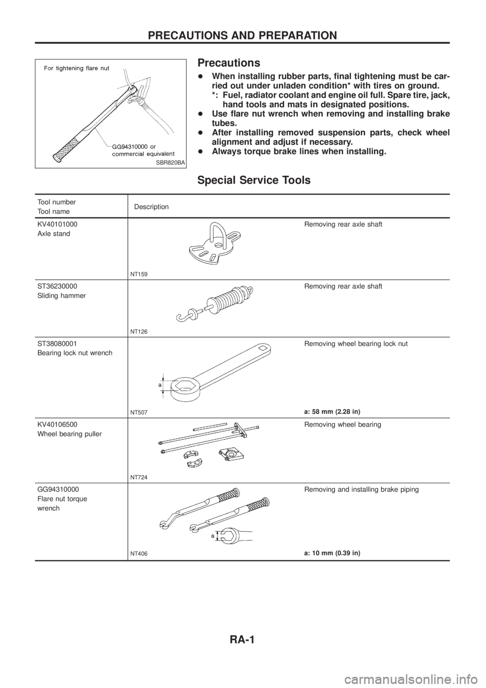
Special Service Tools
Tool number
Tool nameDescription
KV40101000
Axle stand
NT159
Removing rear axle shaft
ST36230000
Sliding hammer
NT126
Removing rear axle shaft
ST38080001
Bearing lock nut wrench
NT507
Removing wheel bearing lock nut
a: 58 mm (2.28 in)
KV40106500
Wheel bearing puller
NT724
Removing wheel bearing
GG94310000
Flare nut torque
wrench
NT406
Removing and installing brake piping
a: 10 mm (0.39 in)
SBR820BA
PRECAUTIONS AND PREPARATION
RA-1