Page 715 of 1226
CAUTION:
+When installing sliding parts such as bearings and
pistons, apply engine oil to the sliding surfaces.
+Place removed parts, such as bearings and bearing caps,
in their proper order and direction.
+When installing connecting rod bolts and main bearing cap
bolts, apply new engine oil to threads and seating surfaces
of nuts.
+Do not allow any magnetic materials to contact the ring
gear teeth of drive plate.
Disassembly
PISTON AND CRANKSHAFT
1. Place engine on a work stand.
2. Remove timing belt and injection pump.
3. Drain coolant and remove water pump.
4. Remove front cover.
5. Drain oil.
6. Remove oil pan and oil pump.
7. Remove cylinder head.
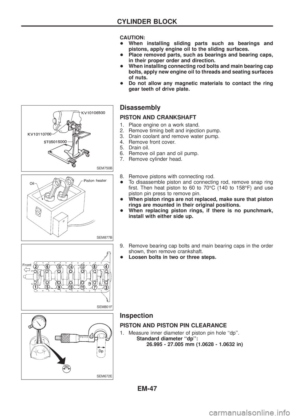
8. Remove pistons with connecting rod.
+To disassemble piston and connecting rod, remove snap ring
®rst. Then heat piston to 60 to 70ÉC (140 to 158ÉF) and use
piston pin press to remove pin.
+When piston rings are not replaced, make sure that piston
rings are mounted in their original positions.
+When replacing piston rings, if there is no punchmark,
install with either side up.
9. Remove bearing cap bolts and main bearing caps in the order
shown, then remove crankshaft.
+Loosen bolts in two or three steps.
Inspection
PISTON AND PISTON PIN CLEARANCE
1. Measure inner diameter of piston pin hole ``dp''.
Standard diameter ``dp'':
26.995 - 27.005 mm (1.0628 - 1.0632 in)
SEM750B
SEM877B
SEM801F
SEM672E
CYLINDER BLOCK
EM-47
Page 721 of 1226
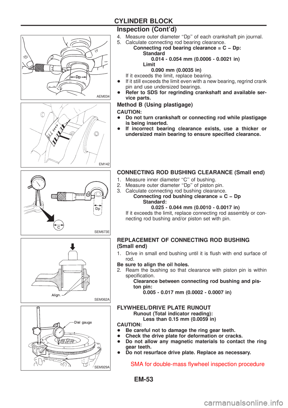
4. Measure outer diameter ``Dp'' of each crankshaft pin journal.
5. Calculate connecting rod bearing clearance.
Connecting rod bearing clearance=CþDp:
Standard
0.014 - 0.054 mm (0.0006 - 0.0021 in)
Limit
0.090 mm (0.0035 in)
If it exceeds the limit, replace bearing.
+If it still exceeds the limit even with a new bearing, regrind crank
pin and use undersized bearings.
+Refer to SDS for regrinding crankshaft and available ser-
vice parts.
Method B (Using plastigage)
CAUTION:
+Do not turn crankshaft or connecting rod while plastigage
is being inserted.
+If incorrect bearing clearance exists, use a thicker or
undersized main bearing to ensure speci®ed clearance.
CONNECTING ROD BUSHING CLEARANCE (Small end)
1. Measure inner diameter ``C'' of bushing.
2. Measure outer diameter ``Dp'' of piston pin.
3. Calculate connecting rod bushing clearance.
Connecting rod bushing clearance=CþDp
Standard:
0.025 - 0.044 mm (0.0010 - 0.0017 in)
If it exceeds the limit, replace connecting rod assembly or con-
necting rod bushing and/or piston set with pin.
REPLACEMENT OF CONNECTING ROD BUSHING
(Small end)
1. Drive in small end bushing until it is ¯ush with end surface of
rod.
Be sure to align the oil holes.
2. Ream the bushing so that clearance with piston pin is within
speci®cation.
Clearance between connecting rod bushing and pis-
ton pin:
0.005 - 0.017 mm (0.0002 - 0.0007 in)
FLYWHEEL/DRIVE PLATE RUNOUT
Runout (Total indicator reading):
Less than 0.15 mm (0.0059 in)
CAUTION:
+Be careful not to damage the ring gear teeth.
+Check the drive plate for deformation or cracks.
+Do not allow any magnetic materials to contact the ring
gear teeth.
+Do not resurface drive plate. Replace as necessary.
AEM034
EM142
SEM673E
SEM062A
SEM929A
CYLINDER BLOCK
Inspection (Cont'd)
EM-53
Page 732 of 1226
Undersize
Unit: mm (in)
Undersize Thickness ``T''Crank pin journal
diameter ``Dp''
0.08 (0.0031)1.536 - 1.540
(0.0605 - 0.0606)
Grind so that bearing
clearance is the
speci®ed value. 0.12 (0.0047)1.556 - 1.560
(0.0613 - 0.0614)
0.25 (0.0098)1.621 - 1.625
(0.0638 - 0.0640)
Bearing clearance
Unit: mm (in)
Main bearing clearance
Standard 0.036 - 0.063 (0.0014 - 0.0025)
Limit 0.12 (0.0047)
Connecting rod bearing clearance
Standard 0.031 - 0.055 (0.0012 - 0.0022)
Limit 0.11 (0.0043)
MISCELLANEOUS COMPONENTS
Unit: mm (in)
Camshaft sprocket runout limit
[TIR]0.1 (0.004)
Flywheel runout limit [TIR] 0.1 (0.004)
Drive plate runout limit [TIR] 0.1 (0.004)
SERVICE DATA AND SPECIFICATIONS (SDS)
Inspection and Adjustment (Cont'd)
EM-64
Page 733 of 1226
FRONT AXLE &
FRONT SUSPENSION
SECTION
FA
CONTENTS
PRECAUTIONS AND PREPARATION............................1
Precautions ..................................................................1
Special Service Tools ..................................................1
Commercial Service Tools ...........................................2
NOISE, VIBRATION AND HARSHNESS (NVH)
TROUBLESHOOTING.....................................................3
NVH Troubleshooting Chart.........................................3
FRONT AXLE AND FRONT SUSPENSION...................4
ON-VEHICLE SERVICE..................................................5
Front Axle and Front Suspension Parts ......................5
Front Wheel Bearing....................................................5
Front Wheel Alignment ................................................8
FRONT AXLE Ð Drive ¯ange and Free-running
Hub.................................................................................10
FRONT AXLE Ð Manual-lock Free-running Hub...... 11
Removal ..................................................................... 11
Installation ..................................................................12
Inspection...................................................................12
FRONT AXLE Ð Auto-lock Free-running Hub..........13
Removal .....................................................................13
Installation ..................................................................13FRONT AXLE Ð Wheel Hub and Rotor Disc............14
Removal and Installation ...........................................14
Inspection...................................................................15
Assembly ...................................................................15
FRONT AXLE Ð Knuckle Flange................................17
Removal .....................................................................17
Inspection...................................................................19
Installation ..................................................................19
Knuckle Flange Grease Seal.....................................21
FRONT AXLE Ð Drive Shaft.......................................23
Inspection...................................................................23
Installation ..................................................................23
FRONT SUSPENSION..................................................24
Shock Absorber .........................................................25
Stabilizer Bar .............................................................25
Coil Spring .................................................................25
Leading Arm...............................................................26
Panhard Rod..............................................................26
SERVICE DATA AND SPECIFICATIONS (SDS)..........27
General Speci®cations ...............................................27
Inspection and Adjustment ........................................27
FA
Page 741 of 1226
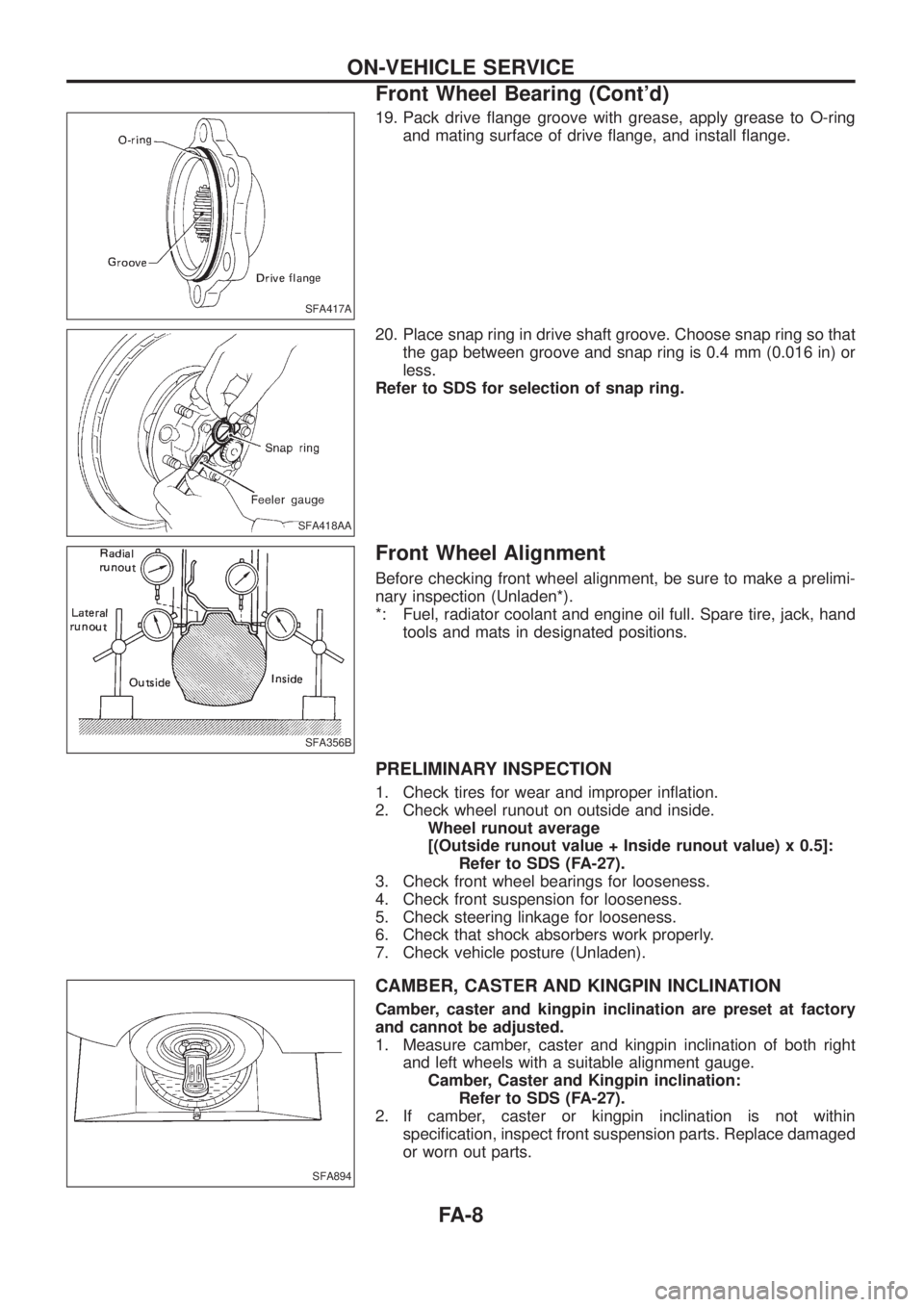
19. Pack drive ¯ange groove with grease, apply grease to O-ring
and mating surface of drive ¯ange, and install ¯ange.
20. Place snap ring in drive shaft groove. Choose snap ring so that
the gap between groove and snap ring is 0.4 mm (0.016 in) or
less.
Refer to SDS for selection of snap ring.
Front Wheel Alignment
Before checking front wheel alignment, be sure to make a prelimi-
nary inspection (Unladen*).
*: Fuel, radiator coolant and engine oil full. Spare tire, jack, hand
tools and mats in designated positions.
PRELIMINARY INSPECTION
1. Check tires for wear and improper in¯ation.
2. Check wheel runout on outside and inside.
Wheel runout average
[(Outside runout value + Inside runout value) x 0.5]:
Refer to SDS (FA-27).
3. Check front wheel bearings for looseness.
4. Check front suspension for looseness.
5. Check steering linkage for looseness.
6. Check that shock absorbers work properly.
7. Check vehicle posture (Unladen).
CAMBER, CASTER AND KINGPIN INCLINATION
Camber, caster and kingpin inclination are preset at factory
and cannot be adjusted.
1. Measure camber, caster and kingpin inclination of both right
and left wheels with a suitable alignment gauge.
Camber, Caster and Kingpin inclination:
Refer to SDS (FA-27).
2. If camber, caster or kingpin inclination is not within
speci®cation, inspect front suspension parts. Replace damaged
or worn out parts.
SFA417A
SFA418AA
SFA356B
SFA894
ON-VEHICLE SERVICE
Front Wheel Bearing (Cont'd)
FA-8
Page 745 of 1226
Installation
Install free-running hub in the reverse order of removal.
Apply multi-purpose grease to bushing and drive clutch
before installing on wheel hub and axle shaft, respectively.
+Install drive clutch.
+Place snap ring in drive shaft groove.
Axial end play:
0.4 mm (0.016 in) or less
Snap ring size:
Refer to SDS.
+When installing manual-lock free-running hub, make sure the
position ``FREE''.
Apply multi-purpose grease to drive shaft end.
+Check operation of manual-lock free-running hub after install-
ing it.
Inspection
+Check that hub moves smoothly and freely.
+Check that clutch moves smoothly in the body.
SFA860B
SFA200
SFA428A
FRONT AXLE Ð Manual-lock Free-running Hub
FA-12
Page 746 of 1226
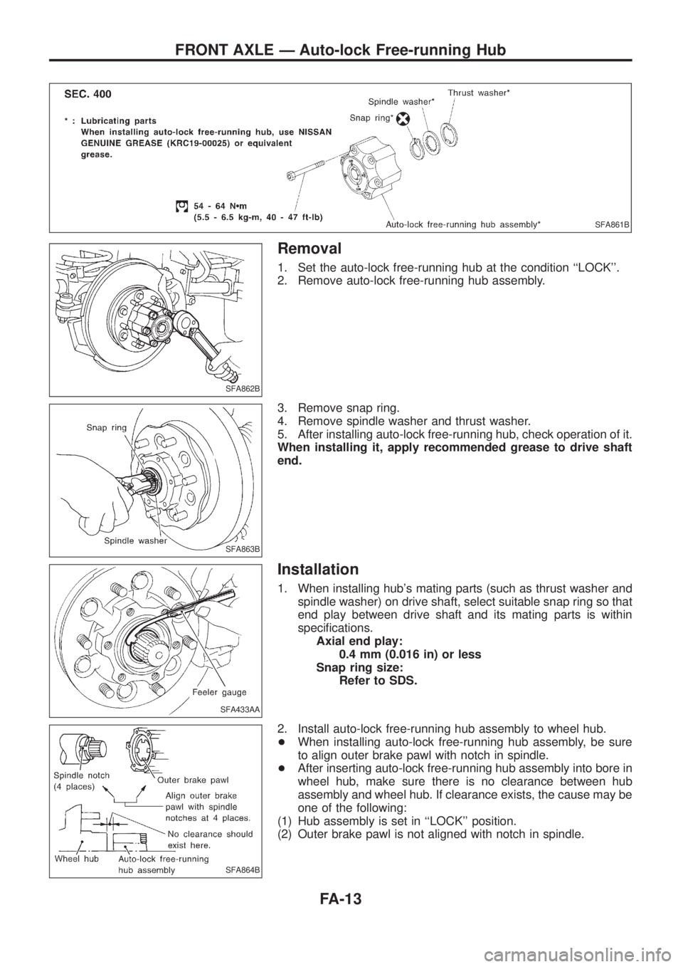
Removal
1. Set the auto-lock free-running hub at the condition ``LOCK''.
2. Remove auto-lock free-running hub assembly.
3. Remove snap ring.
4. Remove spindle washer and thrust washer.
5. After installing auto-lock free-running hub, check operation of it.
When installing it, apply recommended grease to drive shaft
end.
Installation
1. When installing hub's mating parts (such as thrust washer and
spindle washer) on drive shaft, select suitable snap ring so that
end play between drive shaft and its mating parts is within
speci®cations.
Axial end play:
0.4 mm (0.016 in) or less
Snap ring size:
Refer to SDS.
2. Install auto-lock free-running hub assembly to wheel hub.
+When installing auto-lock free-running hub assembly, be sure
to align outer brake pawl with notch in spindle.
+After inserting auto-lock free-running hub assembly into bore in
wheel hub, make sure there is no clearance between hub
assembly and wheel hub. If clearance exists, the cause may be
one of the following:
(1) Hub assembly is set in ``LOCK'' position.
(2) Outer brake pawl is not aligned with notch in spindle.
SFA861B
SFA862B
SFA863B
SFA433AA
SFA864B
FRONT AXLE Ð Auto-lock Free-running Hub
FA-13
Page 750 of 1226
Removal
Drain differential oil completely prior to removal.
1. Remove baffle plate and knuckle spindle.
2. Draw out drive shaft.
Draw out to remove the drive shaft in the axial direction with
the ¯at surface facing up.
SFA867B
SFA868B
SFA869B
FRONT AXLE Ð Knuckle Flange
FA-17