Page 1044 of 1226

Tool number
Tool nameDescriptionUnit application
H233B
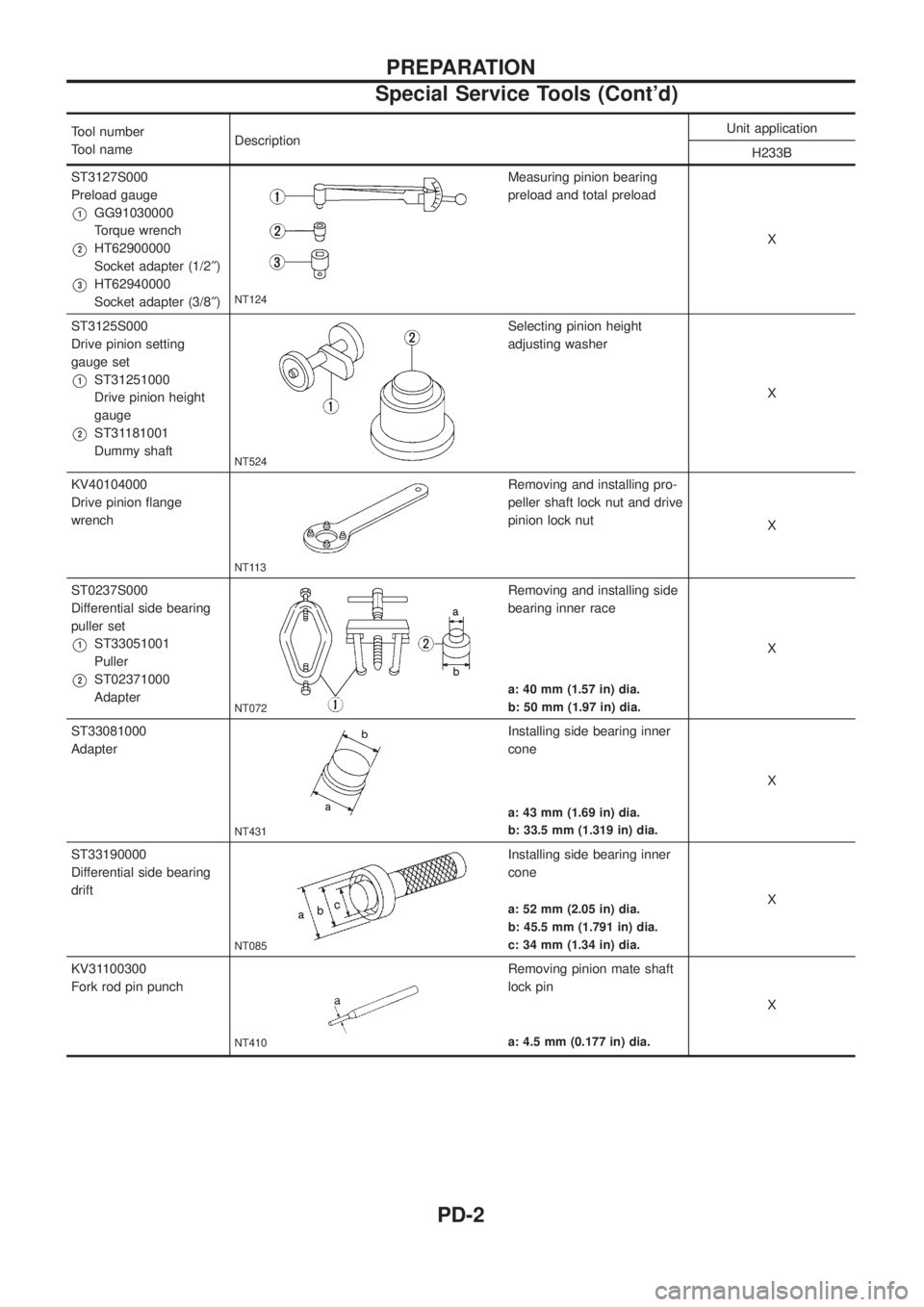
ST3127S000
Preload gauge
V1GG91030000
Torque wrench
V2HT62900000
Socket adapter (1/2²)
V3HT62940000
Socket adapter (3/8²)NT124
Measuring pinion bearing
preload and total preload
X
ST3125S000
Drive pinion setting
gauge set
V1ST31251000
Drive pinion height
gauge
V2ST31181001
Dummy shaft
NT524
Selecting pinion height
adjusting washer
X
KV40104000
Drive pinion ¯ange
wrench
NT113
Removing and installing pro-
peller shaft lock nut and drive
pinion lock nut
X
ST0237S000
Differential side bearing
puller set
V1ST33051001
Puller
V2ST02371000
Adapter
NT072
Removing and installing side
bearing inner race
X
a: 40 mm (1.57 in) dia.
b: 50 mm (1.97 in) dia.
ST33081000
Adapter
NT431
Installing side bearing inner
cone
X
a: 43 mm (1.69 in) dia.
b: 33.5 mm (1.319 in) dia.
ST33190000
Differential side bearing
drift
NT085
Installing side bearing inner
cone
X
a: 52 mm (2.05 in) dia.
b: 45.5 mm (1.791 in) dia.
c: 34 mm (1.34 in) dia.
KV31100300
Fork rod pin punch
NT410
Removing pinion mate shaft
lock pin
X
a: 4.5 mm (0.177 in) dia.
PREPARATION
Special Service Tools (Cont'd)
PD-2
Page 1045 of 1226
Tool number
Tool nameDescription Unit application
H233B
KV381025S0
Oil seal ®tting tool
V1ST30720000
Drift bar
V2KV38102510
Drift
NT525
Installing front oil seal
X
a: 77 mm (3.03 in) dia.
b: 55 mm (2.17 in) dia.
c: 71 mm (2.80 in) dia.
d: 65 mm (2.56 in) dia.
ST32580000
Differentialsidebearing
adjustingnutwrench
ST3125S001 Drive pinion setting gauge set 1 ST3131251000 Height Gauge 2 ST31181001
Dummy Shaft
3 KV38108700 Spacer [thickness: 2.00 mm (0.0787 in)]
NT141
Adjusting side bearing pre-
load and backlash (ring gear-
drive pinion)
X
X
PREPARATION
Special Service Tools (Cont'd)
PD-3
Page 1059 of 1226
11. Remove pinion rear bearing inner cone and drive pinion heightadjusting washer with press and Tool.Toolnumber:ST30031000 (J22912-01)
Differential Case
1. Remove side bearing inner cones.
To prevent damage to bearing, engage puller jaws in groove. Tool number:j
AST33051001 (J22888-20)
j
BST02371000 (J8107-2)
Be careful not to confuse left and right hand parts.
Keep bearing and bearing race for each side together.
2. Loosen ring gear bolts in a criss-cross pattern.
3. Tap ring gear off differential case with a soft hammer.
Tap evenly all around to keep ring gear from binding.
4. Drive out pinion mate shaft lock pin, with punch from ring gear side (2-pinion type differential case).
Lock pin is calked at pin hole mouth on differential case.
SPD018
SPD207A
SPD022
SPD024
SPD025
DISASSEMBLY
Differential Carrier (Cont'd)
PD-17
Page 1069 of 1226
To avoid confusion while calculating bearing shims, it is absolutely
necessary to stay with the metric system. If you measure anything
in inches,the results must be converted to the metric system.
Drive Pinion Height
1. First prepare Tools for pinion height adjustment.
:
V1Heightgauge(ST31251000)*
V2Dummyshaft(ST31181001)*
V3SpacerKV38108700 [thickness: 2.00mm (0.0787 in)]*
V4Feelergauge (commercial servcie tool)
2. To simplify the job, make a chart, like the one below, to orga- nize your calculations.
LETTERS HUNDREDTHS OF
A MILLIMETER
H: Head number
D ¢: Figure marked on dummy shaft
S: Figure marked on height gauge
N:Measuringclearance
* Set tools are available: ST3125S000 (tools 1 and 2) ST3125S001 (tools 1, 2 and 3)
3. Write the following numbers down the chart.H: Head number
D¢: Figure marked on dummy shaft.
SPD758
SPD542
SPD759
ADJUSTMENT
PD-27
Page 1070 of 1226
S: Figure marked on height gauge.
4. Place pinion rear bearing inner cone and Tools on gear carrier.
Tool number:
ST31181001
5. Attach Tool (Height gauge) to gear carrier, and measure the
clearance between the height gauge tip and the dummy shaft
face.
Tool number:
ST31251000
6. Substitute these values into the equation to calculate the thick-
ness of the washer.
If values signifying H, D¢and S are not given, regard them as
zero and calculate.
T (Thickness of washer)
=Nþ[(HþD¢þ S) x 0.01] + 3.05
SPD760
SPD271-A
SPD272-A
PD444-A
PD029
ADJUSTMENT
Drive Pinion Height (Cont'd)
PD-28
Page 1071 of 1226
![NISSAN PATROL 2006 Service Manual Example (H233B):N = 0.30
H=2
D¢=þ1
S=0
T=Nþ[(HþD ¢þS)x0.01]+2.75
=0.40þ[{2þ(þ1)þ0}x0.01]+2.75
(1) H ........................................................................\
2 þD¢........ NISSAN PATROL 2006 Service Manual Example (H233B):N = 0.30
H=2
D¢=þ1
S=0
T=Nþ[(HþD ¢þS)x0.01]+2.75
=0.40þ[{2þ(þ1)þ0}x0.01]+2.75
(1) H ........................................................................\
2 þD¢........](/manual-img/5/57368/w960_57368-1070.png)
Example (H233B):N = 0.30
H=2
D¢=þ1
S=0
T=Nþ[(HþD ¢þS)x0.01]+2.75
=0.40þ[{2þ(þ1)þ0}x0.01]+2.75
(1) H ........................................................................\
2 þD¢................................................................. þ(þ1)
3
þS ...................................................................... þ0
3
(2) 3 x 0.01
0.03
(3)N...................................................................0.40 þ0.03
0.37
(4)0.37 +2.75
3.12
\ T=3.12
7. Select the proper pinion height washer. Drive pinion height adjusting washer:Refer to SDS (PD-0, 53).
If you cannot ®nd the desired thickness of washer, use washer
with thickness closest to the calculated value.
Example (H233B): Calculatedvalue...T=3.12 mm
Usedwasher...T=3.12 mm
Tooth Contact
Gear tooth contact pattern check is necessary to verify correct
relationship between ring gear and drive pinion.
Hypoid gear sets which are not positioned properly in relation to
one another may be noisy, or have short life or both. With a pat-
tern check, the most desirable contact for low noise level and long
life can be assured.
1. Thoroughly clean ring gear and drive pinion teeth.
2. Sparingly apply a mixture of powdered ferric oxide and oil orequivalent to 3 or 4 teeth of ring gear drive side.
SPD005
ADJUSTMENT
Drive Pinion Height (Cont'd)
PD-29
Page 1075 of 1226
Differential Carrier
1. Press-®t front and rear bearing outer races with Tools.
Tool number:
j
AST30611000
j
BST30621000 (front differential)
or suitable pipe
j
CST30701000
CAUTION:
Do not damage roller side face.
2. Select drive pinion height adjusting washer. Refer to ADJUST-
MENT (PD-27).
3. Install drive pinion height adjusting washer in drive pinion, and
press-®t pinion rear bearing inner cone in it, with press and
Tool.
Tool number: ST30911000
4. Place pinion front bearing inner cone in gear carrier.
5. Apply multi-purpose grease to cavity at sealing lips of oil seal.
Install front oil seal.
Tool number:
j
AST30720000
j
BKV38102510
SPD580
SPD377
SPD581
SPD451A
ASSEMBLY
PD-33
Page 1082 of 1226

Assembly
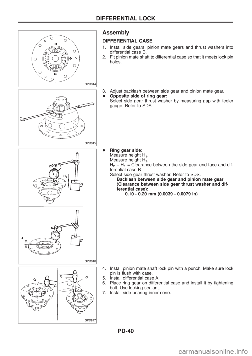
DIFFERENTIAL CASE
1. Install side gears, pinion mate gears and thrust washers into
differential case B.
2. Fit pinion mate shaft to differential case so that it meets lock pin
holes.
3. Adjust backlash between side gear and pinion mate gear.
+Opposite side of ring gear:
Select side gear thrust washer by measuring gap with feeler
gauge. Refer to SDS.
+Ring gear side:
Measure height H
1.
Measure height H
2.
H
2þH1= Clearance between the side gear end face and dif-
ferential case B
Select side gear thrust washer. Refer to SDS.
Backlash between side gear and pinion mate gear
(Clearance between side gear thrust washer and dif-
ferential case):
0.10 - 0.20 mm (0.0039 - 0.0079 in)
4. Install pinion mate shaft lock pin with a punch. Make sure lock
pin is ¯ush with case.
5. Install differential case A.
6. Place ring gear on differential case and install it by tightening
bolt. Use locking sealant.
7. Install side bearing inner cone.
SPD844
SPD845
SPD846
SPD847
DIFFERENTIAL LOCK
PD-40