2006 NISSAN PATROL main tank
[x] Cancel search: main tankPage 44 of 1226

Preliminary Check
Check brake ¯uid level in reservoir
tank.
- ---------------------------------------------------------------------------------------------------------------------------------------------------------------------------------------------------------------------------------------------------------------------------------------------------------------
Low ¯uid level may indicate brake pad
wear or leakage from brake line.
Check brake line for leakage.
OKcNG Repair.
b
Check brake booster for operation and air
tightness. Refer to BR-15.
OK
cNGReplace.
b
Check brake pads and rotor. Refer to
BR-21, 25.
OK
cNGReplace.
Check brake ¯uid level in reservoir tank
again.
OK
cNGFill up brake ¯uid.
Check warning lamp activation.
When ignition switch is turned on, warning
lamp turns on.
OK
cNG
Check fuse, warning lamp
bulb and warning lamp cir-
cuit.
Check warning lamp for deactivation after
engine is started.
OK
cNGGo to Self-diagnosis,
BR-46, 50.
Drive vehicle at speeds over 30 km/h (19
MPH) for at least 1 minute.
Ensure warning lamp remains off while
driving.
OK
cNGGo to Self-diagnosis,
BR-46, 50.
END
SBR451D
SBR389C
SBR058C
SBR059C
SBR186E
.
.
.
.
.
.
.
.
.
TROUBLE DIAGNOSES
BR-40
Page 271 of 1226
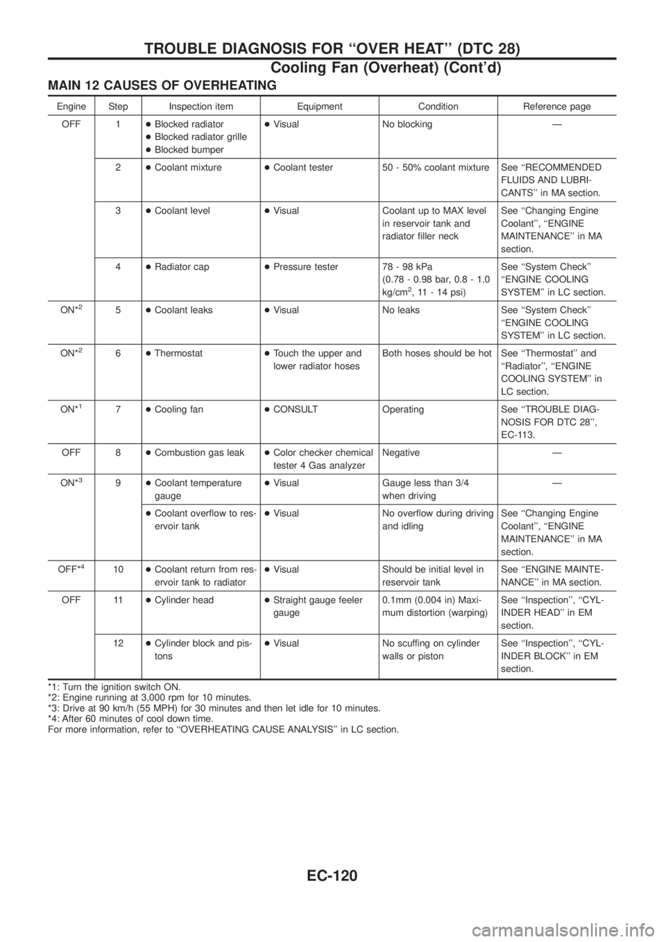
MAIN 12 CAUSES OF OVERHEATING
Engine Step Inspection item Equipment Condition Reference page
OFF 1+Blocked radiator
+Blocked radiator grille
+Blocked bumper+Visual No blocking Ð
2+Coolant mixture+Coolant tester 50 - 50% coolant mixture See ``RECOMMENDED
FLUIDS AND LUBRI-
CANTS'' in MA section.
3+Coolant level+Visual Coolant up to MAX level
in reservoir tank and
radiator ®ller neckSee ``Changing Engine
Coolant'', ``ENGINE
MAINTENANCE'' in MA
section.
4+Radiator cap+Pressure tester 78 - 98 kPa
(0.78 - 0.98 bar, 0.8 - 1.0
kg/cm
2, 11 - 14 psi)See ``System Check''
``ENGINE COOLING
SYSTEM'' in LC section.
ON*
25+Coolant leaks+Visual No leaks See ``System Check''
``ENGINE COOLING
SYSTEM'' in LC section.
ON*
26+Thermostat+Touch the upper and
lower radiator hosesBoth hoses should be hot See ``Thermostat'' and
``Radiator'', ``ENGINE
COOLING SYSTEM'' in
LC section.
ON*
17+Cooling fan+CONSULT Operating See ``TROUBLE DIAG-
NOSIS FOR DTC 28'',
EC-113.
OFF 8+Combustion gas leak+Color checker chemical
tester 4 Gas analyzerNegative Ð
ON*
39+Coolant temperature
gauge+Visual Gauge less than 3/4
when drivingÐ
+Coolant over¯ow to res-
ervoir tank+Visual No over¯ow during driving
and idlingSee ``Changing Engine
Coolant'', ``ENGINE
MAINTENANCE'' in MA
section.
OFF*
410+Coolant return from res-
ervoir tank to radiator+Visual Should be initial level in
reservoir tankSee ``ENGINE MAINTE-
NANCE'' in MA section.
OFF 11+Cylinder head+Straight gauge feeler
gauge0.1mm (0.004 in) Maxi-
mum distortion (warping)See ``Inspection'', ``CYL-
INDER HEAD'' in EM
section.
12+Cylinder block and pis-
tons+Visual No scuffing on cylinder
walls or pistonSee ``Inspection'', ``CYL-
INDER BLOCK'' in EM
section.
*1: Turn the ignition switch ON.
*2: Engine running at 3,000 rpm for 10 minutes.
*3: Drive at 90 km/h (55 MPH) for 30 minutes and then let idle for 10 minutes.
*4: After 60 minutes of cool down time.
For more information, refer to ``OVERHEATING CAUSE ANALYSIS'' in LC section.
TROUBLE DIAGNOSIS FOR ``OVER HEAT'' (DTC 28)
Cooling Fan (Overheat) (Cont'd)
EC-120
Page 458 of 1226
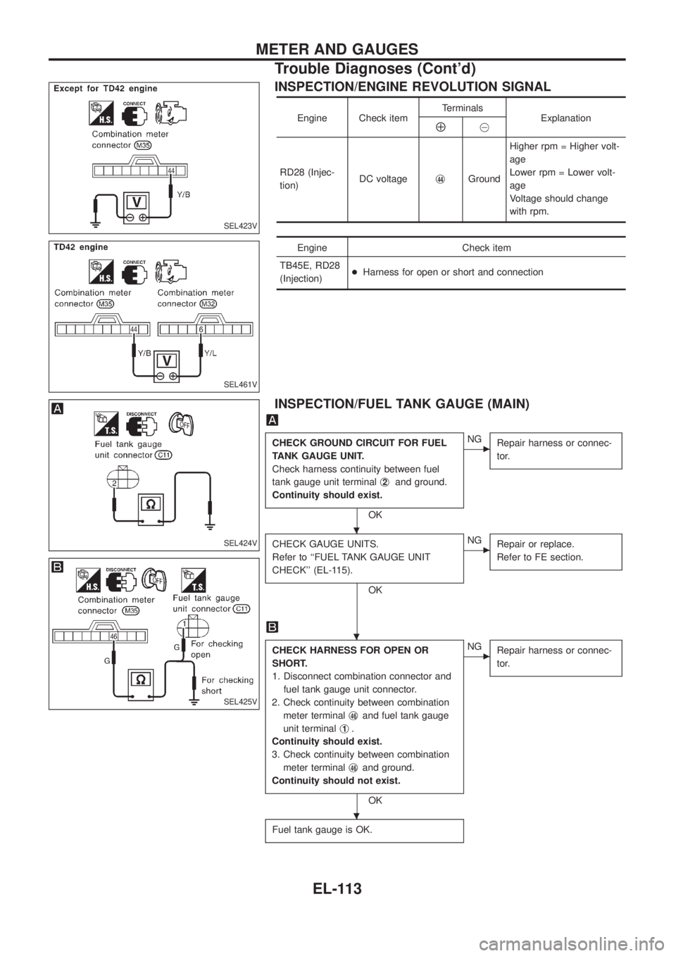
INSPECTION/ENGINE REVOLUTION SIGNAL
Engine Check itemTerminals
ExplanationÅ@
RD28 (Injec-
tion)DC voltagej
44GroundHigher rpm = Higher volt-
age
Lower rpm = Lower volt-
age
Voltage should change
with rpm.
Engine Check item
TB45E, RD28
(Injection)+Harness for open or short and connection
INSPECTION/FUEL TANK GAUGE (MAIN)
CHECK GROUND CIRCUIT FOR FUEL
TANK GAUGE UNIT.
Check harness continuity between fuel
tank gauge unit terminalj
2and ground.
Continuity should exist.
OK
cNG
Repair harness or connec-
tor.
CHECK GAUGE UNITS.
Refer to ``FUEL TANK GAUGE UNIT
CHECK'' (EL-115).
OK
cNG
Repair or replace.
Refer to FE section.
CHECK HARNESS FOR OPEN OR
SHORT.
1. Disconnect combination connector and
fuel tank gauge unit connector.
2. Check continuity between combination
meter terminalj
46and fuel tank gauge
unit terminalj
1.
Continuity should exist.
3. Check continuity between combination
meter terminalj
46and ground.
Continuity should not exist.
OK
cNG
Repair harness or connec-
tor.
Fuel tank gauge is OK.
SEL423V
SEL461V
SEL424V
SEL425V
.
.
.
METER AND GAUGES
Trouble Diagnoses (Cont'd)
EL-113
Page 660 of 1226

Use the chart below to ®nd out what each wiring diagram code
stands for.
Code Section Wiring Diagram Name
A/C,A HA Auto Air Conditioner
A/C CUT EC Air Conditioner Cut Control
A/C,M HA Manual Air Conditioner
A/T AT A/T
AAC/V EC IACV-AAC Valve
ABS BR Anti-lock Brake System
ACC/SW EC Accelerator Switch (FC)
ACL/SW EC Accelerator Position Switch
ADJRES EC Adjustment Resistor
APS EC Accelerator Position Sensor
ASCD EL Automatic Speed Control Device
AT/C EC A/T Control
AUDIO EL Audio
BACK/L EL Back-up Lamp
BCDD EC BCDD System
CD/CHG EL CD Auto Changer
CHARGE EL Charging System
CHIME EL Warning Chime
CHOKE EC Automatic Choke
CIGAR EL Cigarette Lighter
CKPS EC Crankshaft Position Sensor (OBD)
CLOCK EL Clock
CMPS EC Camshaft Position Sensor
COMPAS EL Compass and Thermometer
COOL/B HA Cool Box
COOL/F EC Cooling Fan Control
CORNER EL Cornering Lamp
CSPS EC Control Sleeve Position Sensor
D/LOCK EL Power Door Lock
DEICER EL Wiper Deicer
DEF EL Rear Window Defogger
DIFF/L PD Differential Lock Control System
DTRL ELHeadlamp Ð With Daytime Light
System
ECTS EC Engine Coolant Temperature Sensor
EGRC/V EC EGRC-Solenoid Valve
F/FOG EL Front Fog Lamp
F/PUMP EC Fuel Pump
FCUT EC Fuel Cut Solenoid Valve
FICD EC IACV-FICD Solenoid Valve
FTS EC Fuel Temperature SensorCode Section Wiring Diagram Name
GLOW EC Quick Glow System
GOVNR EC Electric Governor
H/AIM EL Headlamp Aiming Control System
H/LAMP EL Headlamp
HEATUP EC Heat up Switch
HLC EL Headlamp Cleaner
HORN EL Horn
HSEAT EL Heated Seat
IATS EC Intake Air Temperature Sensor
IC/FAN EC Charge Air Cooler Fan
IGN EC Ignition System
IGN/SG EC Ignition Signal
ILL EL Illumination
INJECT EC Injector
INT/L EL Spot, Vanity Mirror Lamps
KS EC Knock Sensor
MAFS EC Mass Air Flow Sensor
MAIN ECMain Power Supply and Ground Cir-
cuit
METER ELSpeedometer, Tachometer, Temp.,
Oil and Fuel Gauges
MIL/DL EC Mil and Data Link Connectors
MIRROR EL Door Mirror
MULTI EL Multi-remote Control System
NATS EL Nissan Anti-Theft System
NLS EC Needle Lift Sensor
P/ANT EL Power Antenna
PLA EC Partial Load Advance Control
PNP/SW EC Park/Neutral Position Switch
POWER EL Power Supply Routing
PST/SW EC Power Steering Oil Pressure Switch
R/COOL HA Rear Cooler System
R/FOG EL Rear Fog Lamp
R/HEAT HA Rear Heater System
ROOM/L EL Interior Room Lamp
S/LOCK EL Power Door Lock Ð Super Lock
S/SIG EC Start Signal
S/TANK FE Sub Fuel Tank Control System
SEAT EL Power Seat
SROOF EL Sunroof
SRS RS Supplemental Restraint System
WIRING DIAGRAM CODES (CELL CODES)
EL-315
Page 832 of 1226
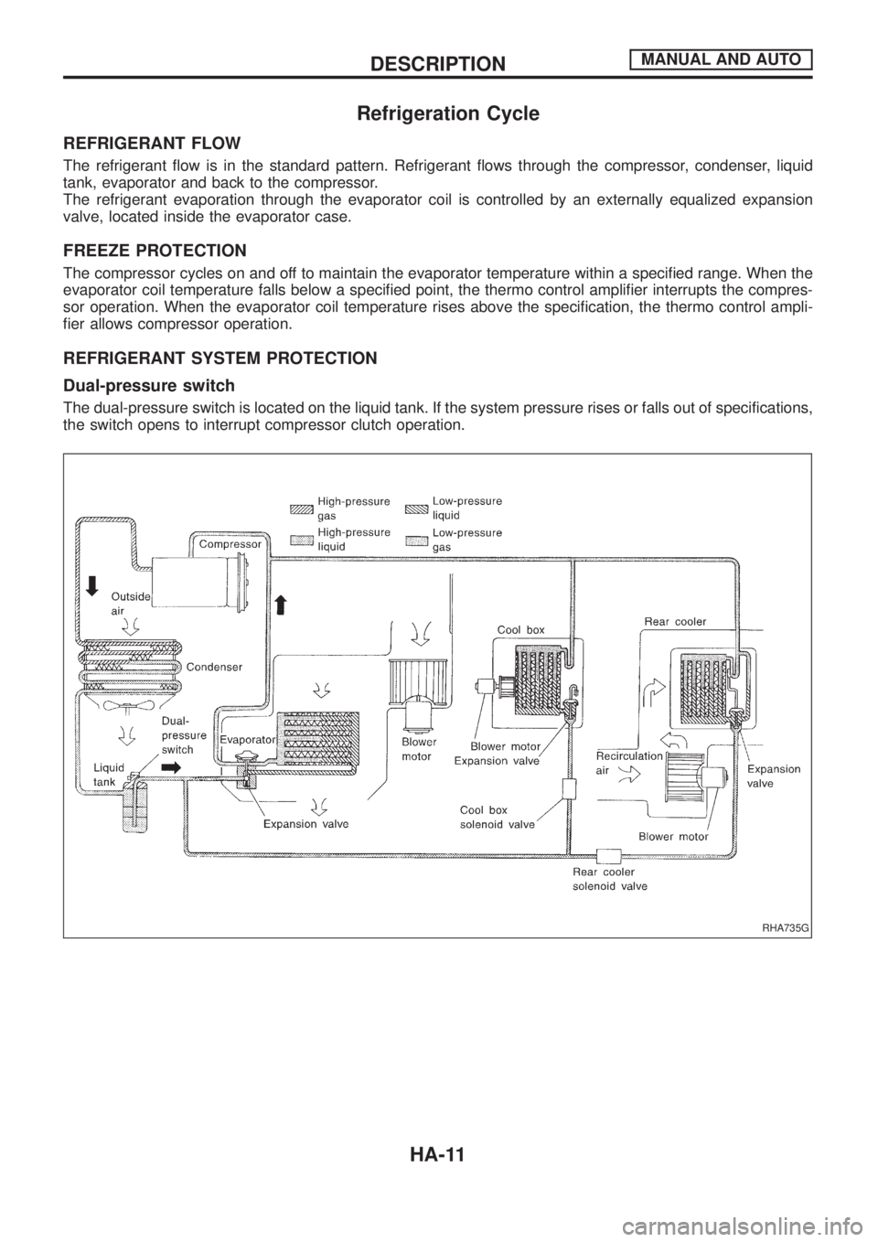
Refrigeration Cycle
REFRIGERANT FLOW
The refrigerant ¯ow is in the standard pattern. Refrigerant ¯ows through the compressor, condenser, liquid
tank, evaporator and back to the compressor.
The refrigerant evaporation through the evaporator coil is controlled by an externally equalized expansion
valve, located inside the evaporator case.
FREEZE PROTECTION
The compressor cycles on and off to maintain the evaporator temperature within a speci®ed range. When the
evaporator coil temperature falls below a speci®ed point, the thermo control ampli®er interrupts the compres-
sor operation. When the evaporator coil temperature rises above the speci®cation, the thermo control ampli-
®er allows compressor operation.
REFRIGERANT SYSTEM PROTECTION
Dual-pressure switch
The dual-pressure switch is located on the liquid tank. If the system pressure rises or falls out of specifications,
the switch opens to interrupt compressor clutch operation.
RHA735G
DESCRIPTIONMANUAL AND AUTO
HA-11
Page 935 of 1226
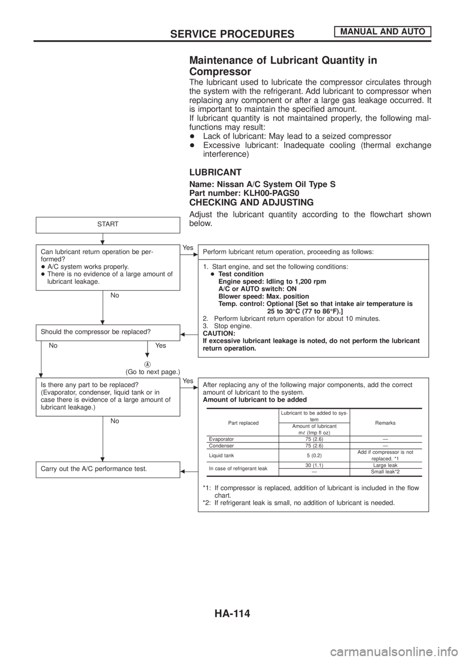
Maintenance of Lubricant Quantity in
Compressor
The lubricant used to lubricate the compressor circulates through
the system with the refrigerant. Add lubricant to compressor when
replacing any component or after a large gas leakage occurred. It
is important to maintain the speci®ed amount.
If lubricant quantity is not maintained properly, the following mal-
functions may result:
+Lack of lubricant: May lead to a seized compressor
+Excessive lubricant: Inadequate cooling (thermal exchange
interference)
LUBRICANT
Name: Nissan A/C System Oil Type S
Part number: KLH00-PAGS0
CHECKING AND ADJUSTING
Adjust the lubricant quantity according to the ¯owchart shown
below.
START
Can lubricant return operation be per-
formed?
+A/C system works properly.
+There is no evidence of a large amount of
lubricant leakage.
No
cYe s
Perform lubricant return operation, proceeding as follows:
------------------------------------------------------------------------------------------------------------------------------------------------------------------------------------------------------------------------------------------------------------------------------------------------------------------------------------------------------------------------------------------------------------------------------------------------------------------------------------------------------------------------------------
1. Start engine, and set the following conditions:
+Test condition
Engine speed: Idling to 1,200 rpm
A/C or AUTO switch: ON
Blower speed: Max. position
Temp. control: Optional [Set so that intake air temperature is
25 to 30ÉC (77 to 86ÉF).]
2. Perform lubricant return operation for about 10 minutes.
3. Stop engine.
CAUTION:
If excessive lubricant leakage is noted, do not perform the lubricant
return operation.
Should the compressor be replaced?
No Yes
b
jA(Go to next page.)
Is there any part to be replaced?
(Evaporator, condenser, liquid tank or in
case there is evidence of a large amount of
lubricant leakage.)
No
cYe s
After replacing any of the following major components, add the correct
amount of lubricant to the system.
Amount of lubricant to be added
*1: If compressor is replaced, addition of lubricant is included in the ¯ow
chart.
*2: If refrigerant leak is small, no addition of lubricant is needed.
Carry out the A/C performance test.b
Part replacedLubricant to be added to sys-
tem
Remarks
Amount of lubricant
m!(Imp ¯ oz)
Evaporator 75 (2.6) Ð
Condenser 75 (2.6) Ð
Liquid tank 5 (0.2)Add if compressor is not
replaced. *1
In case of refrigerant leak30 (1.1) Large leak
Ð Small leak*2
.
.
.
.
.
SERVICE PROCEDURESMANUAL AND AUTO
HA-114
Page 936 of 1226
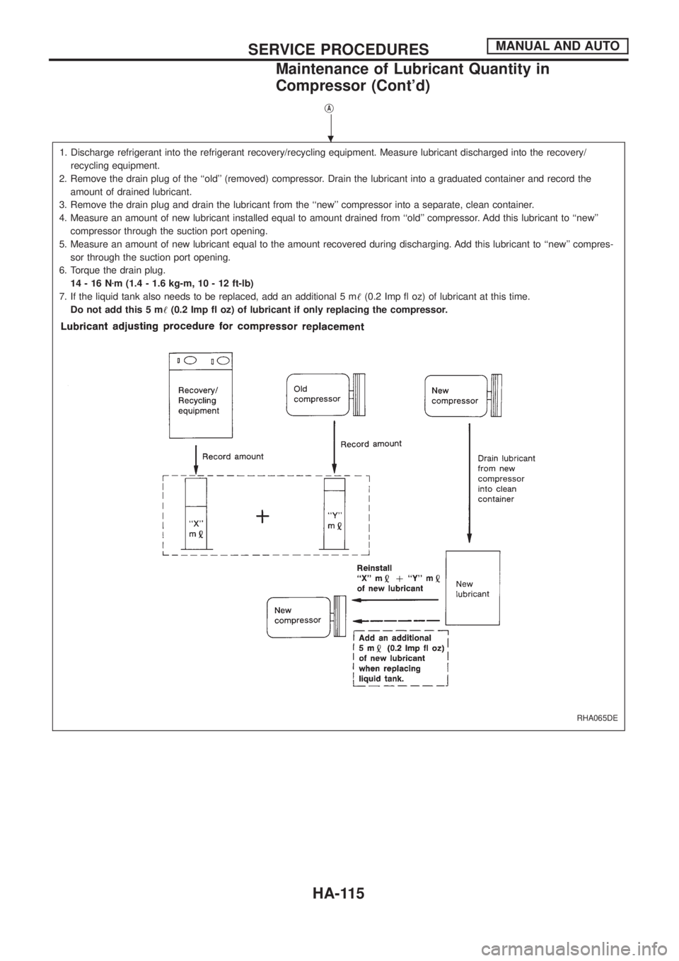
jA
1. Discharge refrigerant into the refrigerant recovery/recycling equipment. Measure lubricant discharged into the recovery/
recycling equipment.
2. Remove the drain plug of the ``old'' (removed) compressor. Drain the lubricant into a graduated container and record the
amount of drained lubricant.
3. Remove the drain plug and drain the lubricant from the ``new'' compressor into a separate, clean container.
4. Measure an amount of new lubricant installed equal to amount drained from ``old'' compressor. Add this lubricant to ``new''
compressor through the suction port opening.
5. Measure an amount of new lubricant equal to the amount recovered during discharging. Add this lubricant to ``new'' compres-
sor through the suction port opening.
6. Torque the drain plug.
14-16Nzm (1.4 - 1.6 kg-m, 10 - 12 ft-lb)
7. If the liquid tank also needs to be replaced, add an additional 5 m!(0.2 Imp ¯ oz) of lubricant at this time.
Do not add this 5 m!(0.2 Imp ¯ oz) of lubricant if only replacing the compressor.
RHA065DE
.
SERVICE PROCEDURESMANUAL AND AUTO
Maintenance of Lubricant Quantity in
Compressor (Cont'd)
HA-115
Page 980 of 1226
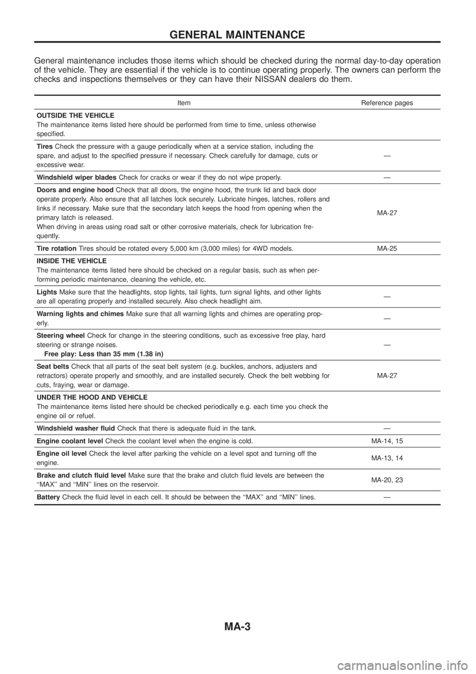
General maintenance includes those items which should be checked during the normal day-to-day operation
of the vehicle. They are essential if the vehicle is to continue operating properly. The owners can perform the
checks and inspections themselves or they can have their NISSAN dealers do them.
Item Reference pages
OUTSIDE THE VEHICLE
The maintenance items listed here should be performed from time to time, unless otherwise
speci®ed.
TiresCheck the pressure with a gauge periodically when at a service station, including the
spare, and adjust to the speci®ed pressure if necessary. Check carefully for damage, cuts or
excessive wear.Ð
Windshield wiper bladesCheck for cracks or wear if they do not wipe properly. Ð
Doors and engine hoodCheck that all doors, the engine hood, the trunk lid and back door
operate properly. Also ensure that all latches lock securely. Lubricate hinges, latches, rollers and
links if necessary. Make sure that the secondary latch keeps the hood from opening when the
primary latch is released.
When driving in areas using road salt or other corrosive materials, check for lubrication fre-
quently.MA-27
Tire rotationTires should be rotated every 5,000 km (3,000 miles) for 4WD models. MA-25
INSIDE THE VEHICLE
The maintenance items listed here should be checked on a regular basis, such as when per-
forming periodic maintenance, cleaning the vehicle, etc.
LightsMake sure that the headlights, stop lights, tail lights, turn signal lights, and other lights
are all operating properly and installed securely. Also check headlight aim.Ð
Warning lights and chimesMake sure that all warning lights and chimes are operating prop-
erly.Ð
Steering wheelCheck for change in the steering conditions, such as excessive free play, hard
steering or strange noises.
Free play: Less than 35 mm (1.38 in)Ð
Seat beltsCheck that all parts of the seat belt system (e.g. buckles, anchors, adjusters and
retractors) operate properly and smoothly, and are installed securely. Check the belt webbing for
cuts, fraying, wear or damage.MA-27
UNDER THE HOOD AND VEHICLE
The maintenance items listed here should be checked periodically e.g. each time you check the
engine oil or refuel.
Windshield washer ¯uidCheck that there is adequate ¯uid in the tank. Ð
Engine coolant levelCheck the coolant level when the engine is cold. MA-14, 15
Engine oil levelCheck the level after parking the vehicle on a level spot and turning off the
engine.MA-13, 14
Brake and clutch ¯uid levelMake sure that the brake and clutch ¯uid levels are between the
``MAX'' and ``MIN'' lines on the reservoir.MA-20, 23
BatteryCheck the ¯uid level in each cell. It should be between the ``MAX'' and ``MIN'' lines. Ð
GENERAL MAINTENANCE
MA-3