Page 802 of 1226
CONTROL UNIT CIRCUIT TEST
System Description: When the switch is ON, the control unit lights up the lamp.
AGI059
HOW TO PERFORM EFFICIENT DIAGNOSIS FOR AN ELECTRICAL INCIDENT
Circuit Inspection (Cont'd)
GI-29
Page 817 of 1226

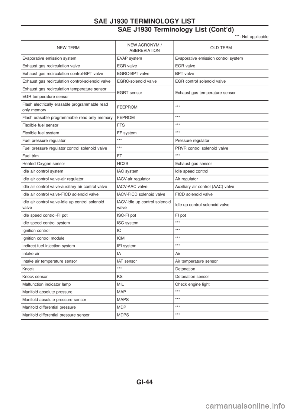
***: Not applicable
NEW TERMNEW ACRONYM /
ABBREVIATIONOLD TERM
Evaporative emission system EVAP system Evaporative emission control system
Exhaust gas recirculation valve EGR valve EGR valve
Exhaust gas recirculation control-BPT valve EGRC-BPT valve BPT valve
Exhaust gas recirculation control-solenoid valve EGRC-solenoid valve EGR control solenoid valve
Exhaust gas recirculation temperature sensor
EGRT sensor Exhaust gas temperature sensor
EGR temperature sensor
Flash electrically erasable programmable read
only memoryFEEPROM ***
Flash erasable programmable read only memory FEPROM ***
Flexible fuel sensor FFS ***
Flexible fuel system FF system ***
Fuel pressure regulator *** Pressure regulator
Fuel pressure regulator control solenoid valve *** PRVR control solenoid valve
Fuel trim FT ***
Heated Oxygen sensor HO2S Exhaust gas sensor
Idle air control system IAC system Idle speed control
Idle air control valve-air regulator IACV-air regulator Air regulator
Idle air control valve-auxiliary air control valve IACV-AAC valve Auxiliary air control (AAC) valve
Idle air control valve-FICD solenoid valve IACV-FICD solenoid valve FICD solenoid valve
Idle air control valve-idle up control solenoid
valveIACV-idle up control solenoid
valveIdle up control solenoid valve
Idle speed control-FI pot ISC-FI pot FI pot
Idle speed control system ISC system ***
Ignition control IC ***
Ignition control module ICM ***
Indirect fuel injection system IFI system ***
Intake air IA Air
Intake air temperature sensor IAT sensor Air temperature sensor
Knock *** Detonation
Knock sensor KS Detonation sensor
Malfunction indicator lamp MIL Check engine light
Manifold absolute pressure MAP ***
Manifold absolute pressure sensor MAPS ***
Manifold differential pressure MDP ***
Manifold differential pressure sensor MDPS ***
SAE J1930 TERMINOLOGY LIST
SAE J1930 Terminology List (Cont'd)
GI-44
Page 828 of 1226

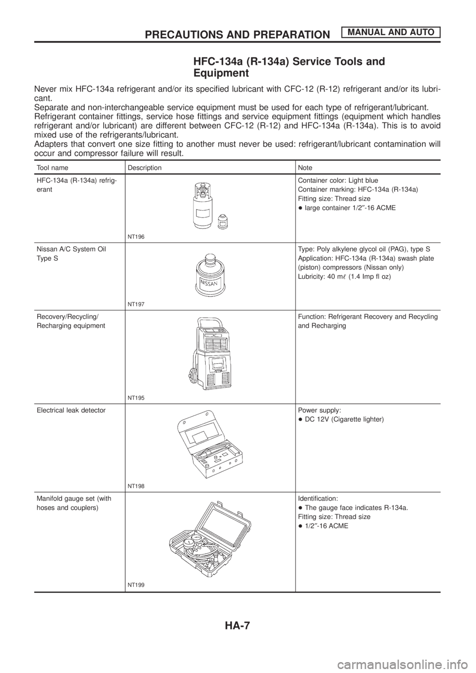
HFC-134a (R-134a) Service Tools and
Equipment
Never mix HFC-134a refrigerant and/or its speci®ed lubricant with CFC-12 (R-12) refrigerant and/or its lubri-
cant.
Separate and non-interchangeable service equipment must be used for each type of refrigerant/lubricant.
Refrigerant container ®ttings, service hose ®ttings and service equipment ®ttings (equipment which handles
refrigerant and/or lubricant) are different between CFC-12 (R-12) and HFC-134a (R-134a). This is to avoid
mixed use of the refrigerants/lubricant.
Adapters that convert one size ®tting to another must never be used: refrigerant/lubricant contamination will
occur and compressor failure will result.
Tool name Description Note
HFC-134a (R-134a) refrig-
erant
NT196
Container color: Light blue
Container marking: HFC-134a (R-134a)
Fitting size: Thread size
+large container 1/2²-16 ACME
Nissan A/C System Oil
Type S
NT197
Type: Poly alkylene glycol oil (PAG), type S
Application: HFC-134a (R-134a) swash plate
(piston) compressors (Nissan only)
Lubricity: 40 m!(1.4 Imp ¯ oz)
Recovery/Recycling/
Recharging equipment
NT195
Function: Refrigerant Recovery and Recycling
and Recharging
Electrical leak detector
NT198
Power supply:
+DC 12V (Cigarette lighter)
Manifold gauge set (with
hoses and couplers)
NT199
Identi®cation:
+The gauge face indicates R-134a.
Fitting size: Thread size
+1/2²-16 ACME
PRECAUTIONS AND PREPARATIONMANUAL AND AUTO
HA-7
Page 837 of 1226
System Description
SWITCH AND THEIR CONTROL FUNCTIONS
Knob/SwitchKnob/Switch position
Air outlet Intake air Compressor
A/C
A/CjÐ Ð ON*
Mode
jVENT Ð Ð
jB/L Ð Ð
jFOOT Ð Ð
jD/F FRE Ð
jDEF FRE ON*
jÐÐÐ
*: Compressor is operated by dual-pressure switch.
Control Operation
FAN CONTROL KNOB
This knob turns the fan ON and OFF, and controls fan speed.
MODE CONTROL KNOB
This knob controls the outlet air ¯ow.
TEMPERATURE CONTROL KNOB
This knob allows adjustment of the temperature of the outlet air.
RECIRCULATION (REC) SWITCH
OFF position: Outside air is drawn into the passenger compartment.
ON position: Interior air is recirculated inside the vehicle. The indicator lamp will also light.
AIR CONDITIONER SWITCH
The air conditioner switch controls the A/C system. When the switch is depressed with the fan ON, the com-
pressor will turn ON. The indicator lamp will also light.
The air conditioner cooling function operates only when the engine is running.
RHA582G
DESCRIPTIONMANUAL
HA-16
Page 844 of 1226
3. Check recirculation
a. Press recirculation switch.
Recirculation indicator should light.
b. Listen for intake door position change (you should hear blower
sound change slightly).
4. Check temperature decrease
a. Turn temperature control knob to full cold.
b. Check for cold air at discharge air outlets.
5. Check temperature increase
a. Turn temperature control knob to full hot.
b. Check for hot air at discharge air outlets.
6. Check air conditioner switch
Turn fan control knob to the desired (1 to 4-speed) position and
push the air conditioner switch to turn ON the air conditioner.
The indicator light should come on when air conditioner is ON.
RHA585G
RHA586G
RHA587G
RHA588G
TROUBLE DIAGNOSESMANUAL
Operational Check (Cont'd)
HA-23
Page 886 of 1226
jA
STEP 2 - SENSOR CIRCUITS ARE
CHECKED FOR OPEN OR SHORT
CIRCUIT.
Does code No.
appear on the dis-
play?
Ye sNo
.
Turn temperature
dial clockwise.Refer to the following chart for malfunctioning code
No.
(If two or more sensors malfunction, corresponding
code Nos. blink respectively two times.)
*1: Conduct self-diagnosis STEP 2 under sunshine.
When conducting indoors, aim a light (more than
60W) at sunload sensor, otherwise Code No.
will indicate despite that sunload sensor is func-
tioning properly. j
B
(Go to next page.)
Code No.Malfunctioning sensor
(including circuits)Reference
page
Ambient sensor HA-103A/C LED
In-vehicle sensor HA-105A/C LED
Sunload sensor*1 HA-107A/C LED
Air mix door motor
(LCU) PBRHA-79
A/C LED
RHA970DA
RHA528G
RHA501A
.
.
.
TROUBLE DIAGNOSESAUTO
Self-diagnosis (Cont'd)
HA-65
Page 892 of 1226
b. Con®rm that discharge air comes out according to the air dis-
tribution table at left.
Refer to ``Discharge Air Flow'' (HA-13).
NOTE:
Con®rm that the compressor clutch is engaged (visualinspec-
tion) and intake door position is at FRESH when the DEF
is selected.
Intake door position is checked in the next step.
4. Check recirculation
a. Press RECswitch.
Recirculation indicator should illuminate.
b. Listen for intake door position change (you should hear blower
sound change slightly).
5. Check temperature dial
a. Turn temperature dial counterclockwise until 18ÉC is displayed.
b. Check for cold air at discharge air outlets.
c. Turn temperature dial clockwise until 32ÉC is displayed.
d. Check for hot air at discharge air outlets.
RHA654FD
RHA521G
RHA522G
TROUBLE DIAGNOSESAUTO
Operational Check (Cont'd)
HA-71
Page 893 of 1226
6. Check AUTO mode
a. Press AUTO switch.
b. Display should indicate AUTO.
Con®rm that the compressor clutch engages (audio or visual
inspection).
(Discharge air and blower speed will depend on ambient,
in-vehicle, and set temperatures.)
7. Check FRESH switch
a. Press FRE switch.
FRESH indicator should illuminate.
b. Listen for intake door position change. (You should hear a slight
change in blower sound.)
8. Check A/C switch
a. Press A/C switch.
A/C indicator should illuminate.
b. Con®rm that the compressor clutch is engaged.
RHA523G
RHA524G
RHA525G
TROUBLE DIAGNOSESAUTO
Operational Check (Cont'd)
HA-72