Page 1139 of 1226

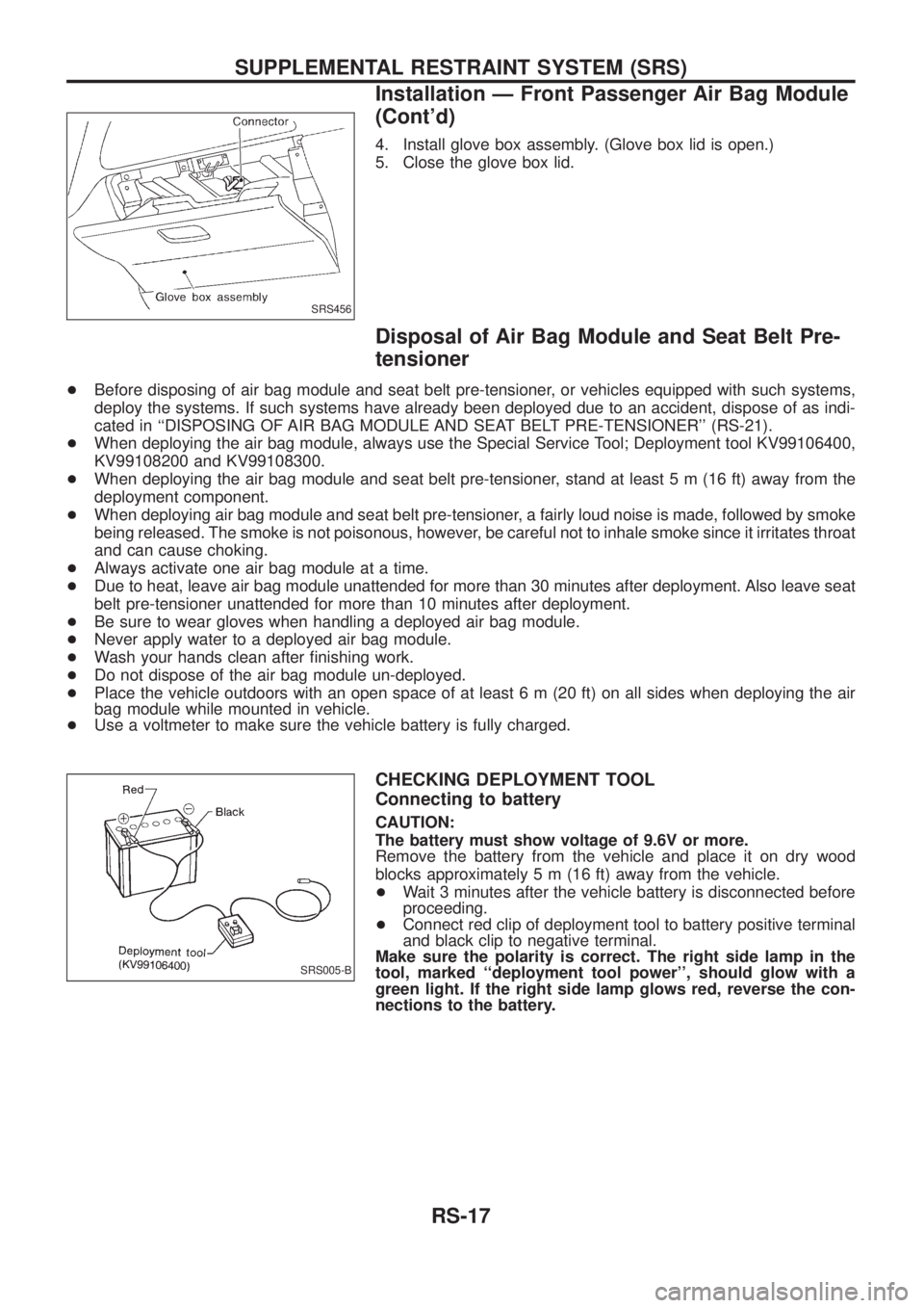
4. Install glove box assembly. (Glove box lid is open.)
5. Close the glove box lid.
Disposal of Air Bag Module and Seat Belt Pre-
tensioner
+Before disposing of air bag module and seat belt pre-tensioner, or vehicles equipped with such systems,
deploy the systems. If such systems have already been deployed due to an accident, dispose of as indi-
cated in ``DISPOSING OF AIR BAG MODULE AND SEAT BELT PRE-TENSIONER'' (RS-21).
+When deploying the air bag module, always use the Special Service Tool; Deployment tool KV99106400,
KV99108200 and KV99108300.
+When deploying the air bag module and seat belt pre-tensioner, stand at least 5 m (16 ft) away from the
deployment component.
+When deploying air bag module and seat belt pre-tensioner, a fairly loud noise is made, followed by smoke
being released. The smoke is not poisonous, however, be careful not to inhale smoke since it irritates throat
and can cause choking.
+Always activate one air bag module at a time.
+Due to heat, leave air bag module unattended for more than 30 minutes after deployment. Also leave seat
belt pre-tensioner unattended for more than 10 minutes after deployment.
+Be sure to wear gloves when handling a deployed air bag module.
+Never apply water to a deployed air bag module.
+Wash your hands clean after ®nishing work.
+Do not dispose of the air bag module un-deployed.
+Place the vehicle outdoors with an open space of at least 6 m (20 ft) on all sides when deploying the air
bag module while mounted in vehicle.
+Use a voltmeter to make sure the vehicle battery is fully charged.
CHECKING DEPLOYMENT TOOL
Connecting to battery
CAUTION:
The battery must show voltage of 9.6V or more.
Remove the battery from the vehicle and place it on dry wood
blocks approximately 5 m (16 ft) away from the vehicle.
+Wait 3 minutes after the vehicle battery is disconnected before
proceeding.
+Connect red clip of deployment tool to battery positive terminal
and black clip to negative terminal.
Make sure the polarity is correct. The right side lamp in the
tool, marked ``deployment tool power'', should glow with a
green light. If the right side lamp glows red, reverse the con-
nections to the battery.
SRS456
SRS005-B
SUPPLEMENTAL RESTRAINT SYSTEM (SRS)
Installation Ð Front Passenger Air Bag Module
(Cont'd)
RS-17
Page 1153 of 1226

Checking seat belt pre-tensioner system operation
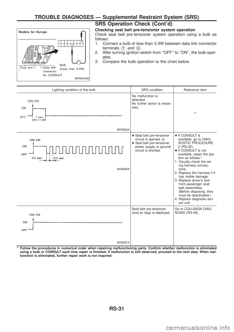
Check seat belt pre-tensioner system operation using a bulb as
follows:
1. Connect a bulb of less than 3.4W between data link connector
terminals
V7andV11.
2. After turning ignition switch from ``OFF'' to ``ON'', the bulb oper-
ates.
3. Compare the bulb operation to the chart below.
Lighting condition of the bulb SRS condition Reference item
MRS095A
No malfunction is
detected.
No further action is neces-
sary.
Ð
MRS096A
+Seat belt pre-tensioner
circuit is opened, or
+Seat belt pre-tensioner
power supply or ground
circuit is shorted.+If CONSULT is
available, go to DIAG-
NOSTIC PROCEDURE
2 (RS-32).
+If CONSULT is not
available, repair the sys-
tem as follows.*
1. Visually check the wir-
ing harness connec-
tions.
2. Replace the harness if it
has visible damage.
3. Replace driver's and
front passenger seat
belt assemblies.
(Before disposing, they
must be deactivated.)
4. Replace diagnosis sen-
sor unit.
MRS097A
Seat belt pre-tensioner
(and air bag) is deployed.Go to COLLISION DIAG-
NOSIS (RS-45).
* Follow the procedures in numerical order when repairing malfunctioning parts. Con®rm whether malfunction is eliminated
using a bulb or CONSULT each time repair is ®nished. If malfunction is still observed, proceed to the next step. When mal-
function is eliminated, further repair work is not required.
MRS054AB
TROUBLE DIAGNOSES Ð Supplemental Restraint System (SRS)
SRS Operation Check (Cont'd)
RS-31
Page 1175 of 1226

Bleeding Hydraulic System
1. Raise front end of vehicle until wheels are clear of the ground.
2. Add ¯uid into oil tank to speci®ed level. Then, quickly turn steer-
ing wheel fully to right and left and lightly touch steering stop-
pers.
Repeat steering wheel operation until ¯uid level no longer
decreases.
3. Start engine.
Repeat step 2 above.
+Incomplete air bleeding will cause the following to occur. When
this happens, bleed air again.
a. Air bubbles in reservoir tank
b. Clicking noise in oil pump
c. Excessive buzzing in oil pump
Fluid noise may occur in the valve or oil pump. This is common
when the vehicle is stationary or while turning steering wheel
slowly. This does not affect performance or durability of the system.
Checking Steering Wheel Turning Force
1. Park vehicle on a level, dry surface and set parking brake.
2. Start engine.
3. Bring power steering ¯uid up to adequate operating tempera-
ture. [Make sure temperature of ¯uid is approximately 60 to
80ÉC (140 to 176ÉF).]
Tires need to be in¯ated to normal pressure.
4. Check steering wheel turning force when steering wheel has
been turned 360É from the neutral position.
Steering wheel turning force:
39 N (4 kg, 9 lb) or less
Checking Hydraulic System
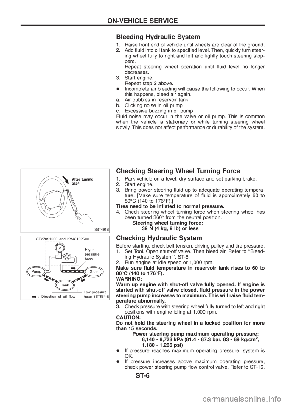
Before starting, check belt tension, driving pulley and tire pressure.
1. Set Tool. Open shut-off valve. Then bleed air. Refer to ``Bleed-
ing Hydraulic System'', ST-6.
2. Run engine at idle speed or 1,000 rpm.
Make sure ¯uid temperature in reservoir tank rises to 60 to
80ÉC (140 to 176ÉF).
WARNING:
Warm up engine with shut-off valve fully opened. If engine is
started with shut-off valve closed, ¯uid pressure in the power
steering pump increases to maximum. This will raise ¯uid tem-
perature abnormally.
3. Check pressure with steering wheel fully turned to left and right
positions with engine idling at 1,000 rpm.
CAUTION:
Do not hold the steering wheel in a locked position for more
than 15 seconds.
Power steering pump maximum operating pressure:
8,140 - 8,728 kPa (81.4 - 87.3 bar, 83 - 89 kg/cm
2,
1,180 - 1,266 psi)
+If pressure reaches maximum operating pressure, system is
OK.
+If pressure increases above maximum operating pressure,
check power steering pump ¯ow control valve. Refer to ST-16.
SST491B
SST834-E
ON-VEHICLE SERVICE
ST-6
Page 1180 of 1226
Inspection
+When steering wheel does not turn smoothly, check the steer-
ing column as follows and replace damaged parts.
a. Check column bearings for damage and unevenness. Lubricate
with recommended multi-purpose grease or replace steering
column as an assembly, if necessary.
b. Check steering column lower shaft for deformation and break-
age. Replace if necessary.
+When the vehicle comes into a light collision, check length ``L
1''
and ``L
2''.
Steering column length ``L
1'':
679.9 - 681.5 mm (26.77 - 26.83 in)
Steering column lower shaft length ``L
2'':
489.3 - 493.3 mm (19.26 - 19.42 in)
If out of the speci®cations, replace steering column shaft or
steering column as an assembly.
Tilt mechanism
After installing steering column, check tilt mechanism operation.
SST761C
SST582BD
STEERING WHEEL AND STEERING COLUMN
ST-11
Page 1211 of 1226
f. Remove counter gear by tapping it lightly with a soft hammer.
g. Remove main gear by tapping it lightly with a soft hammer.
SMT261D
SMT262D
DISASSEMBLY
TF-18
Page 1220 of 1226
1. Install cross shaft.
2. Assemble front case.
a. Install main gear assembly by tapping it lightly with a soft ham-
mer.
b. Apply sealant to the mating surface and bolts of front case
cover and install it on front case.
+Apply recommended sealant to these ten bolts.
+Tightening torque
A:
:16-21Nzm (1.6 - 2.1 kg-m, 12 - 15 ft-lb)
B:
:19-24Nzm (1.9 - 2.4 kg-m, 14 - 17 ft-lb)
c. Apply gear oil to needle bearing and install it into main gear.
d. Install counter gear assembly by tapping it lightly with a soft
hammer.
SMT151B
SMT152B
SMT153B
SMT326A
SMT264D
ASSEMBLY
TF-27
Page 1222 of 1226
b. Select suitable shim using SDS table as a guide.
Counter gear rear bearing shim:
Refer to SDS, TF-33.
4. Place suitable shim on counter gear rear bearing with grease.
5. Apply gear oil to each part in front case.
6. Install mainshaft on center case.
a. Install mainshaft on center case by tapping it lightly.
+Apply gear oil to mainshaft front bearing.
b. Install bearing retainer.
c. Install low gear and its bearing to mainshaft.
+Apply gear oil to needle bearing.
SMT157B
SMT158B
SMT159B
SMT407A
SMT160B
ASSEMBLY
TF-29
Page 1223 of 1226
d. Install L & H hub and snap ring to mainshaft.
+Pay attention to direction of L & H hub.
e. Measure end play of low gear.
Standard:
0.20 - 0.35 mm (0.0079 - 0.0138 in)
7. Apply sealant to mating surface and put center case assembly
onto front case and tighten bolts.
8. Assemble center case assembly.
a. Put drive chain onto front drive sprocket and front drive shaft,
and then put them in center case.
b. Install front drive shaft by tapping it lightly with a soft hammer.
+Make sure shafts are lined up in case.
SMT161B
SMT117B
SMT163B
SMT164B
SMT165B
ASSEMBLY
TF-30