2006 NISSAN PATROL light
[x] Cancel search: lightPage 604 of 1226
Trouble Diagnoses
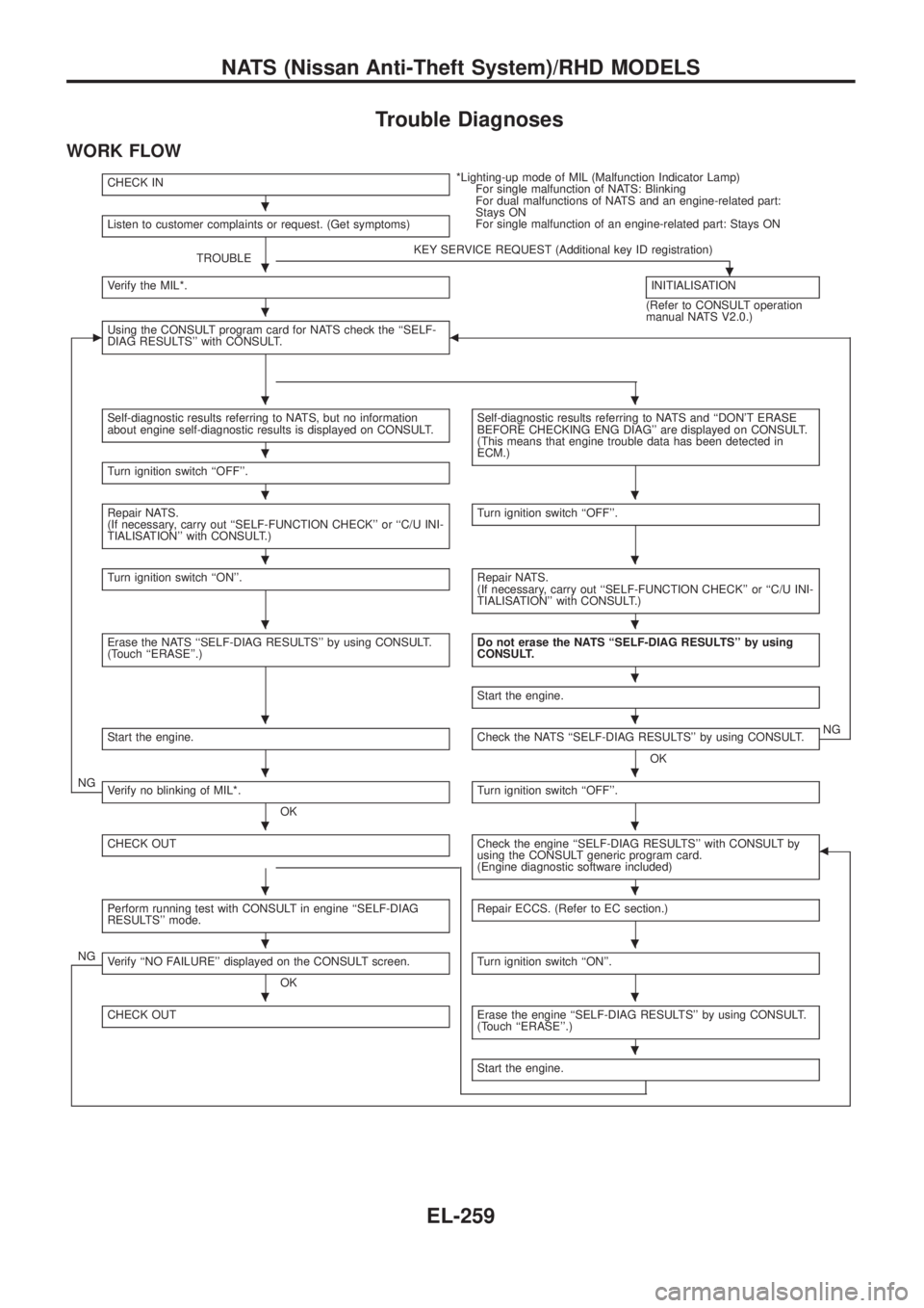
WORK FLOW
CHECK IN*Lighting-up mode of MIL (Malfunction Indicator Lamp)
For single malfunction of NATS: Blinking
For dual malfunctions of NATS and an engine-related part:
Stays ON
For single malfunction of an engine-related part: Stays ON
Listen to customer complaints or request. (Get symptoms)
TROUBLEKEY SERVICE REQUEST (Additional key ID registration).Verify the MIL*.INITIALISATION
(Refer to CONSULT operation
manual NATS V2.0.)
cUsing the CONSULT program card for NATS check the ``SELF-
DIAG RESULTS'' with CONSULT.b
Self-diagnostic results referring to NATS, but no information
about engine self-diagnostic results is displayed on CONSULT.Self-diagnostic results referring to NATS and ``DON'T ERASE
BEFORE CHECKING ENG DIAG'' are displayed on CONSULT.
(This means that engine trouble data has been detected in
ECM.)
Turn ignition switch ``OFF''.
Repair NATS.
(If necessary, carry out ``SELF-FUNCTION CHECK'' or ``C/U INI-
TIALISATION'' with CONSULT.)Turn ignition switch ``OFF''.
Turn ignition switch ``ON''.Repair NATS.
(If necessary, carry out ``SELF-FUNCTION CHECK'' or ``C/U INI-
TIALISATION'' with CONSULT.)
Erase the NATS ``SELF-DIAG RESULTS'' by using CONSULT.
(Touch ``ERASE''.)Do not erase the NATS ``SELF-DIAG RESULTS'' by using
CONSULT.
Start the engine.
Start the engine.Check the NATS ``SELF-DIAG RESULTS'' by using CONSULT.
OKNG
NGVerify no blinking of MIL*.
OKTurn ignition switch ``OFF''.
CHECK OUTCheck the engine ``SELF-DIAG RESULTS'' with CONSULT by
using the CONSULT generic program card.
(Engine diagnostic software included)b
Perform running test with CONSULT in engine ``SELF-DIAG
RESULTS'' mode.Repair ECCS. (Refer to EC section.)
NGVerify ``NO FAILURE'' displayed on the CONSULT screen.
OKTurn ignition switch ``ON''.
CHECK OUTErase the engine ``SELF-DIAG RESULTS'' by using CONSULT.
(Touch ``ERASE''.)
Start the engine.
.
.
.
..
.
..
..
..
.
..
..
..
..
..
..
.
NATS (Nissan Anti-Theft System)/RHD MODELS
EL-259
Page 605 of 1226
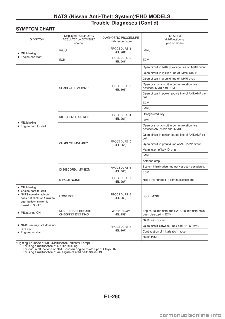
SYMPTOM CHART
SYMPTOMDisplayed ``SELF-DIAG
RESULTS'' on CONSULT
screen.DIAGNOSTIC PROCEDURE
(Reference page)SYSTEM
(Malfunctioning
part or mode)
+MIL blinking
+Engine can start.IMMUPROCEDURE 1
(EL-261)IMMU
ECMPROCEDURE 2
(EL-261)ECM
+MIL blinking
+Engine hard to startCHAIN OF ECM-IMMUPROCEDURE 3
(EL-262)Open circuit in battery voltage line of IMMU circuit
Open circuit in ignition line of IMMU circuit
Open circuit in ground line of IMMU circuit
Open or short circuit in communication line
between IMMU and ECM
Open circuit in power source line of ANT/AMP cir-
cuit
ECM
IMMU
DIFFERENCE OF KEYPROCEDURE 4
(EL-264)Unregistered key
IMMU
CHAIN OF IMMU-KEYPROCEDURE 5
(EL-265)Open or short circuit in communication line
between ANT/AMP and IMMU
Open circuit in power source line of ANT/AMP cir-
cuit
Open circuit in ground line of ANT/AMP circuit
Malfunction of key ID chip
IMMU
Antenna amp.
ID DISCORD, IMM-ECMPROCEDURE 6
(EL-266)System initialisation has not yet been completed.
ECM
MINGLE NOISEPROCEDURE 7
(EL-267)Noise interference in communication line
+MIL blinking
+Engine hard to start
+NATS security indicator
does not blink for 1 minute
after ignition switch is
turned to ``OFF''.LOCK MODEPROCEDURE 9
(EL-268)LOCK MODE
+MIL staying ONDON'T ERASE BEFORE
CHECKING ENG DIAGWORK FLOW
(EL-259)Engine trouble data and NATS trouble data have
been detected in ECM
+NATS security ind. does not
light up.
+Engine can start.ÐPROCEDURE 8
(EL-267)NATS security ind.
Open circuit between Fuse and NATS IMMU
Continuation of initialisation mode
NATS IMMU
*Lighting-up mode of MIL (Malfunction Indicator Lamp)
For single malfunction of NATS: Blinking
For dual malfunctions of NATS and an engine-related part: Stays ON
For single malfunction of an engine-related part: Stays ON
NATS (Nissan Anti-Theft System)/RHD MODELS
Trouble Diagnoses (Cont'd)
EL-260
Page 612 of 1226
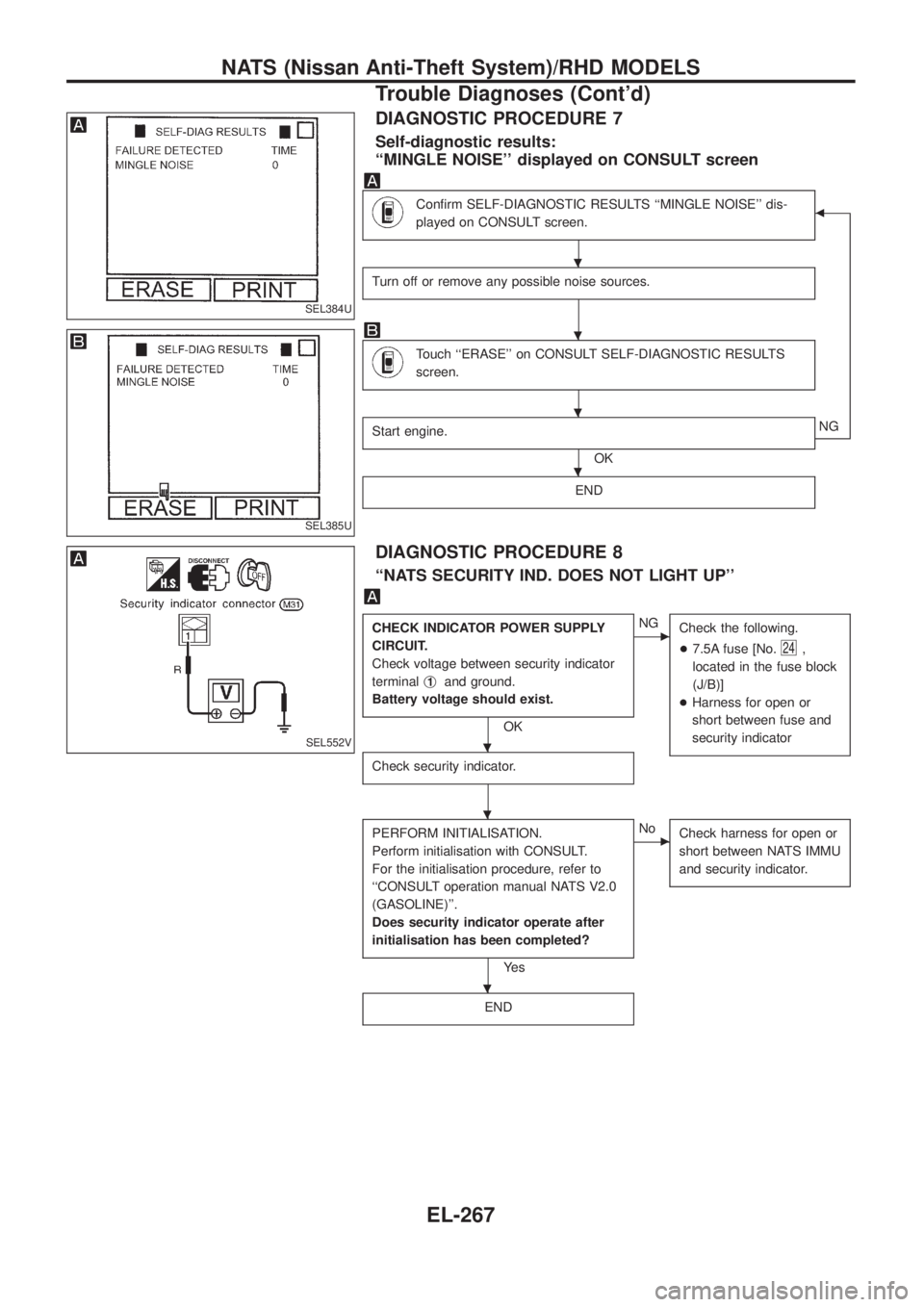
DIAGNOSTIC PROCEDURE 7
Self-diagnostic results:
``MINGLE NOISE'' displayed on CONSULT screen
Con®rm SELF-DIAGNOSTIC RESULTS ``MINGLE NOISE'' dis-
played on CONSULT screen.b
Turn off or remove any possible noise sources.
Touch ``ERASE'' on CONSULT SELF-DIAGNOSTIC RESULTS
screen.
Start engine.
OKNG
END
DIAGNOSTIC PROCEDURE 8
``NATS SECURITY IND. DOES NOT LIGHT UP''
CHECK INDICATOR POWER SUPPLY
CIRCUIT.
Check voltage between security indicator
terminalj
1and ground.
Battery voltage should exist.
OK
cNG
Check the following.
+7.5A fuse [No.
24,
located in the fuse block
(J/B)]
+Harness for open or
short between fuse and
security indicator
Check security indicator.
PERFORM INITIALISATION.
Perform initialisation with CONSULT.
For the initialisation procedure, refer to
``CONSULT operation manual NATS V2.0
(GASOLINE)''.
Does security indicator operate after
initialisation has been completed?
Ye s
cNo
Check harness for open or
short between NATS IMMU
and security indicator.
END
SEL384U
SEL385U
SEL552V
.
.
.
.
.
.
.
NATS (Nissan Anti-Theft System)/RHD MODELS
Trouble Diagnoses (Cont'd)
EL-267
Page 660 of 1226

Use the chart below to ®nd out what each wiring diagram code
stands for.
Code Section Wiring Diagram Name
A/C,A HA Auto Air Conditioner
A/C CUT EC Air Conditioner Cut Control
A/C,M HA Manual Air Conditioner
A/T AT A/T
AAC/V EC IACV-AAC Valve
ABS BR Anti-lock Brake System
ACC/SW EC Accelerator Switch (FC)
ACL/SW EC Accelerator Position Switch
ADJRES EC Adjustment Resistor
APS EC Accelerator Position Sensor
ASCD EL Automatic Speed Control Device
AT/C EC A/T Control
AUDIO EL Audio
BACK/L EL Back-up Lamp
BCDD EC BCDD System
CD/CHG EL CD Auto Changer
CHARGE EL Charging System
CHIME EL Warning Chime
CHOKE EC Automatic Choke
CIGAR EL Cigarette Lighter
CKPS EC Crankshaft Position Sensor (OBD)
CLOCK EL Clock
CMPS EC Camshaft Position Sensor
COMPAS EL Compass and Thermometer
COOL/B HA Cool Box
COOL/F EC Cooling Fan Control
CORNER EL Cornering Lamp
CSPS EC Control Sleeve Position Sensor
D/LOCK EL Power Door Lock
DEICER EL Wiper Deicer
DEF EL Rear Window Defogger
DIFF/L PD Differential Lock Control System
DTRL ELHeadlamp Ð With Daytime Light
System
ECTS EC Engine Coolant Temperature Sensor
EGRC/V EC EGRC-Solenoid Valve
F/FOG EL Front Fog Lamp
F/PUMP EC Fuel Pump
FCUT EC Fuel Cut Solenoid Valve
FICD EC IACV-FICD Solenoid Valve
FTS EC Fuel Temperature SensorCode Section Wiring Diagram Name
GLOW EC Quick Glow System
GOVNR EC Electric Governor
H/AIM EL Headlamp Aiming Control System
H/LAMP EL Headlamp
HEATUP EC Heat up Switch
HLC EL Headlamp Cleaner
HORN EL Horn
HSEAT EL Heated Seat
IATS EC Intake Air Temperature Sensor
IC/FAN EC Charge Air Cooler Fan
IGN EC Ignition System
IGN/SG EC Ignition Signal
ILL EL Illumination
INJECT EC Injector
INT/L EL Spot, Vanity Mirror Lamps
KS EC Knock Sensor
MAFS EC Mass Air Flow Sensor
MAIN ECMain Power Supply and Ground Cir-
cuit
METER ELSpeedometer, Tachometer, Temp.,
Oil and Fuel Gauges
MIL/DL EC Mil and Data Link Connectors
MIRROR EL Door Mirror
MULTI EL Multi-remote Control System
NATS EL Nissan Anti-Theft System
NLS EC Needle Lift Sensor
P/ANT EL Power Antenna
PLA EC Partial Load Advance Control
PNP/SW EC Park/Neutral Position Switch
POWER EL Power Supply Routing
PST/SW EC Power Steering Oil Pressure Switch
R/COOL HA Rear Cooler System
R/FOG EL Rear Fog Lamp
R/HEAT HA Rear Heater System
ROOM/L EL Interior Room Lamp
S/LOCK EL Power Door Lock Ð Super Lock
S/SIG EC Start Signal
S/TANK FE Sub Fuel Tank Control System
SEAT EL Power Seat
SROOF EL Sunroof
SRS RS Supplemental Restraint System
WIRING DIAGRAM CODES (CELL CODES)
EL-315
Page 763 of 1226
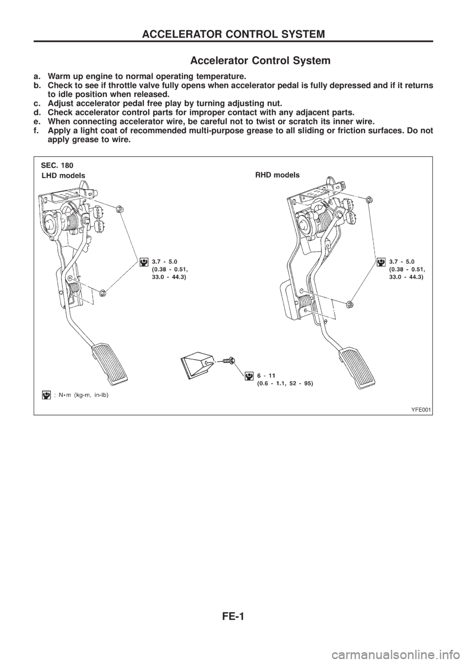
Accelerator Control System
a. Warm up engine to normal operating temperature.
b. Check to see if throttle valve fully opens when accelerator pedal is fully depressed and if it returns
to idle position when released.
c. Adjust accelerator pedal free play by turning adjusting nut.
d. Check accelerator control parts for improper contact with any adjacent parts.
e. When connecting accelerator wire, be careful not to twist or scratch its inner wire.
f. Apply a light coat of recommended multi-purpose grease to all sliding or friction surfaces. Do not
apply grease to wire.
YFE001
ACCELERATOR CONTROL SYSTEM
FE-1
Page 783 of 1226
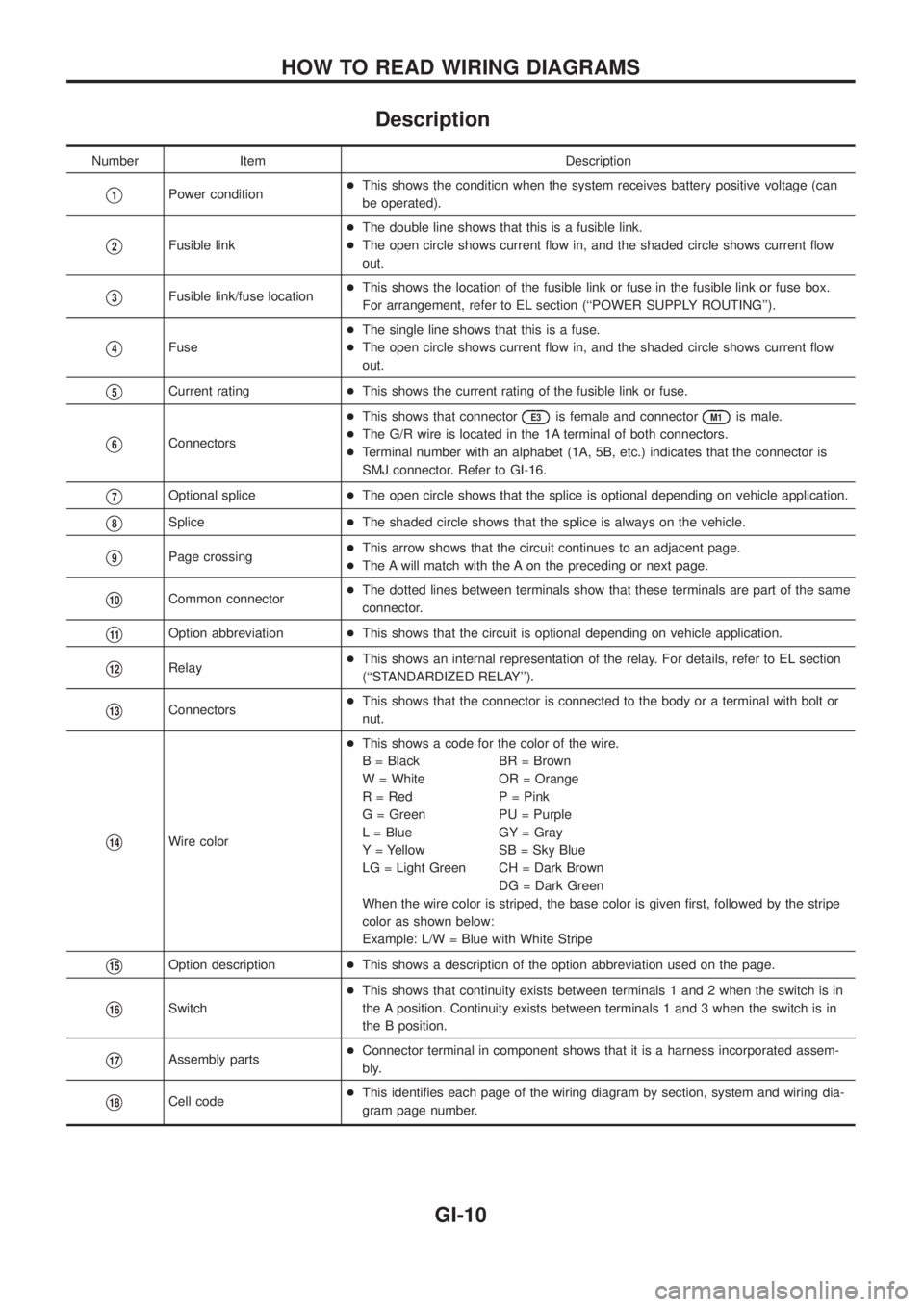
Description
Number Item Description
V1Power condition+This shows the condition when the system receives battery positive voltage (can
be operated).
V2Fusible link+The double line shows that this is a fusible link.
+The open circle shows current ¯ow in, and the shaded circle shows current ¯ow
out.
V3Fusible link/fuse location+This shows the location of the fusible link or fuse in the fusible link or fuse box.
For arrangement, refer to EL section (``POWER SUPPLY ROUTING'').
V4Fuse+The single line shows that this is a fuse.
+The open circle shows current ¯ow in, and the shaded circle shows current ¯ow
out.
V5Current rating+This shows the current rating of the fusible link or fuse.
V6Connectors+This shows that connector
E3is female and connectorM1is male.
+The G/R wire is located in the 1A terminal of both connectors.
+Terminal number with an alphabet (1A, 5B, etc.) indicates that the connector is
SMJ connector. Refer to GI-16.
V7Optional splice+The open circle shows that the splice is optional depending on vehicle application.
V8Splice+The shaded circle shows that the splice is always on the vehicle.
V9Page crossing+This arrow shows that the circuit continues to an adjacent page.
+The A will match with the A on the preceding or next page.
V10Common connector+The dotted lines between terminals show that these terminals are part of the same
connector.
V11Option abbreviation+This shows that the circuit is optional depending on vehicle application.
V12Relay+This shows an internal representation of the relay. For details, refer to EL section
(``STANDARDIZED RELAY'').
V13Connectors+This shows that the connector is connected to the body or a terminal with bolt or
nut.
V14Wire color+This shows a code for the color of the wire.
B = Black BR = Brown
W = White OR = Orange
R = Red P = Pink
G = Green PU = Purple
L = Blue GY = Gray
Y = Yellow SB = Sky Blue
LG = Light Green CH = Dark Brown
DG = Dark Green
When the wire color is striped, the base color is given ®rst, followed by the stripe
color as shown below:
Example: L/W = Blue with White Stripe
V15Option description+This shows a description of the option abbreviation used on the page.
V16Switch+This shows that continuity exists between terminals 1 and 2 when the switch is in
the A position. Continuity exists between terminals 1 and 3 when the switch is in
the B position.
V17Assembly parts+Connector terminal in component shows that it is a harness incorporated assem-
bly.
V18Cell code+This identi®es each page of the wiring diagram by section, system and wiring dia-
gram page number.
HOW TO READ WIRING DIAGRAMS
GI-10
Page 794 of 1226
Incident Simulation Tests
INTRODUCTION
Sometimes the symptom is not present when the vehicle is brought in for service. If possible, re-create the
conditions present at the time of the incident. Doing so may help avoid a No Trouble Found Diagnosis. The
following section illustrates ways to simulate the conditions/environment under which the owner experiences
an electrical incident.
The section is broken into the six following topics:
+Vehicle vibration
+Heat sensitive
+Freezing
+Water intrusion
+Electrical load
+Cold or hot start up
Get a thorough description of the incident from the customer. It is important for simulating the conditions of
the problem.
VEHICLE VIBRATION
The problem may occur or become worse while driving on a rough road or when engine is vibrating (idle with
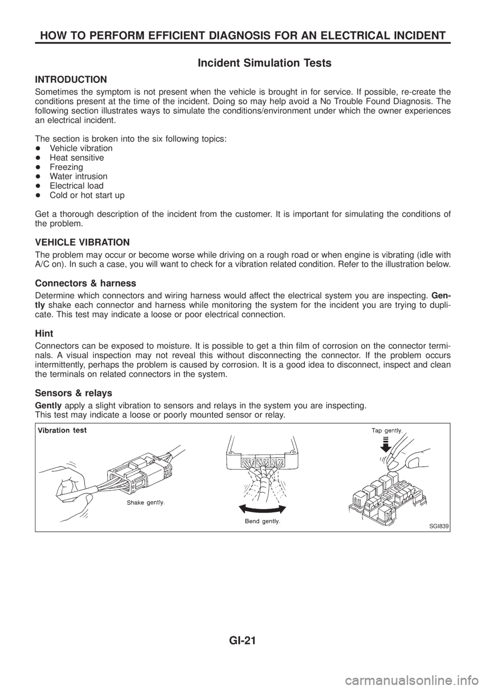
A/C on). In such a case, you will want to check for a vibration related condition. Refer to the illustration below.
Connectors & harness
Determine which connectors and wiring harness would affect the electrical system you are inspecting.Gen-
tlyshake each connector and harness while monitoring the system for the incident you are trying to dupli-
cate. This test may indicate a loose or poor electrical connection.
Hint
Connectors can be exposed to moisture. It is possible to get a thin ®lm of corrosion on the connector termi-
nals. A visual inspection may not reveal this without disconnecting the connector. If the problem occurs
intermittently, perhaps the problem is caused by corrosion. It is a good idea to disconnect, inspect and clean
the terminals on related connectors in the system.
Sensors & relays
Gentlyapply a slight vibration to sensors and relays in the system you are inspecting.
This test may indicate a loose or poorly mounted sensor or relay.
SGI839
HOW TO PERFORM EFFICIENT DIAGNOSIS FOR AN ELECTRICAL INCIDENT
GI-21
Page 800 of 1226
VOLTAGE DROP TESTS
Voltage drop tests are often used to ®nd components or circuits which have excessive resistance. A voltage
drop in a circuit is caused by a resistancewhen the circuit is in operation.
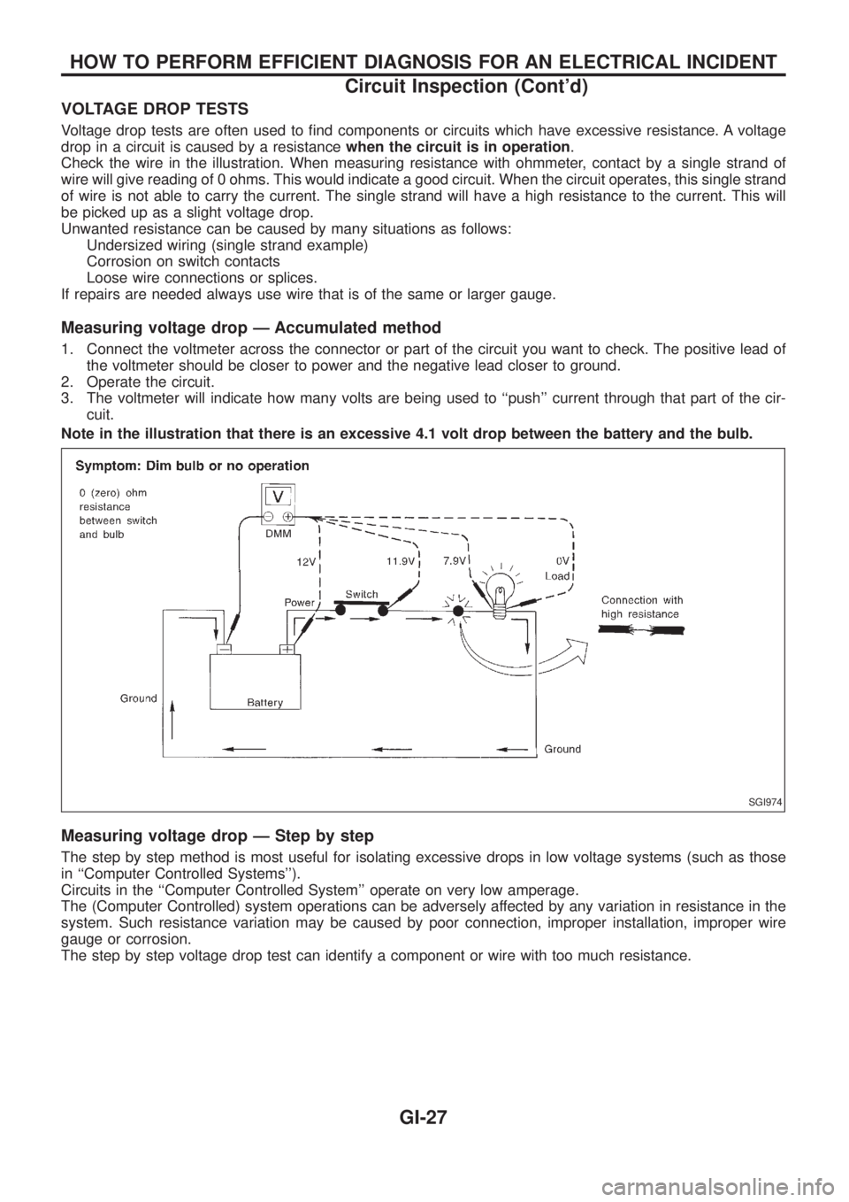
Check the wire in the illustration. When measuring resistance with ohmmeter, contact by a single strand of
wire will give reading of 0 ohms. This would indicate a good circuit. When the circuit operates, this single strand
of wire is not able to carry the current. The single strand will have a high resistance to the current. This will
be picked up as a slight voltage drop.
Unwanted resistance can be caused by many situations as follows:
Undersized wiring (single strand example)
Corrosion on switch contacts
Loose wire connections or splices.
If repairs are needed always use wire that is of the same or larger gauge.
Measuring voltage drop Ð Accumulated method
1. Connect the voltmeter across the connector or part of the circuit you want to check. The positive lead of
the voltmeter should be closer to power and the negative lead closer to ground.
2. Operate the circuit.
3. The voltmeter will indicate how many volts are being used to ``push'' current through that part of the cir-
cuit.
Note in the illustration that there is an excessive 4.1 volt drop between the battery and the bulb.
Measuring voltage drop Ð Step by step
The step by step method is most useful for isolating excessive drops in low voltage systems (such as those
in ``Computer Controlled Systems'').
Circuits in the ``Computer Controlled System'' operate on very low amperage.
The (Computer Controlled) system operations can be adversely affected by any variation in resistance in the
system. Such resistance variation may be caused by poor connection, improper installation, improper wire
gauge or corrosion.
The step by step voltage drop test can identify a component or wire with too much resistance.
SGI974
HOW TO PERFORM EFFICIENT DIAGNOSIS FOR AN ELECTRICAL INCIDENT
Circuit Inspection (Cont'd)
GI-27