2006 MERCEDES-BENZ SPRINTER air condition
[x] Cancel search: air conditionPage 2137 of 2305
CAUTION: Use only the specified O-rings as they
are made of a special material for the R-134a sys-
tem. The use of any other O-rings may allow the
connection to leak intermittently during vehicle
operation.
(4) Lubricate the male fitting and O-rings, and the
inside of the female fitting with clean R-134a refrig-
erant oil. Use only refrigerant oil of the type recom-
mended for the compressor in the vehicle.
(5) Fit the female half of the coupler fitting over
the male half of the fitting.
(6) Push together firmly on the two halves of the
coupler fitting until the garter spring in the cage on
the male half of the fitting snaps over the flanged
end on the female half of the fitting.
(7) Ensure that the spring-lock coupler is fully
engaged by trying to separate the two coupler halves.
This is done by pulling the refrigerant lines on either
side of the coupler away from each other.
(8) Reinstall the secondary retaining clip over the
spring-lock coupler cage.
(9) Evacuate the refrigerant system (Refer to 24 -
HEATING & AIR CONDITIONING/PLUMBING -
STANDARD PROCEDURE - REFRIGERANT SYS-
TEM EVACUATE).
(10) Charge the refrigerant system (Refer to 24 -
HEATING & AIR CONDITIONING/PLUMBING -
STANDARD PROCEDURE - REFRIGERANT SYS-
TEM CHARGE).
UNDERBODY LINES
REMOVAL
WARNING: Refer to the applicable warnings and
cautions for this system before performing the fol-
lowing operation (Refer to 24 - HEATING & AIR
CONDITIONING/PLUMBING - WARNINGS) and (Refer
to 24 - HEATING & AIR CONDITIONING/PLUMBING -
CAUTIONS). Failure to follow the warnings and cau-
tions could result in possible personal injury or
death.
NOTE: The underbody refrigerant lines for the
optional rear A/C system are serviced in five sec-
tions. Two sections are connected the A/C compres-
sor. Two sections of the underbody suction line
(low-side) are connected together by a tapping
block with an O-ring seal. The underbody A/C dis-
charge line uses a spring-lock type refrigerant line
coupler with an O-ring seal.
DISCHARGE LINE
(1) Remove the cover from the rear A/C evaporator
housing (Refer to 24 - HEATING & AIR CONDI-TIONING/DISTRIBUTION - REAR/A/C EVAPORA-
TOR COVER-REAR - REMOVAL).
(2) Recover the refrigerant from the rear refriger-
ant system (Refer to 24 - HEATING & AIR CONDI-
TIONING/PLUMBING - STANDARD PROCEDURE -
REFRIGERANT RECOVERY).
(3) Raise and support the vehicle.
(4) Using the proper A/C line disconnect tool, dis-
connect the underbody discharge line spring-lock cou-
pler from the compressor section of the underbody
discharge line and remove and discard the O-ring
seal (Refer to 24 - HEATING & AIR CONDITION-
ING/PLUMBING/REFRIGERANT LINE COUPLER -
REMOVAL) (Fig. 39).
(5) Disconnect the underbody discharge line from
the rear A/C discharge line and remove and discard
the O-ring seal.
(6) Install plug in, or tape over all of the opened
discharge line fittings.
(7) Disengage the fuel lines from the retaining clip
located near the transmission and position the fuel
lines out of the way.
(8) Remove the screws and brackets that secure
the discharge line to the underneath of the vehicle.
(9) Support transmission with a suitable lifting
device and remove the rear transmission crossmem-
ber (Refer to 13 - FRAME & BUMPERS/FRAME/
REAR CROSSMEMBER-TRANSMISSION -
REMOVAL).
(10) Remove the underbody discharge line from
the vehicle. Push the discharge line forward and over
the transmission, then pull it rearward to remove.
(11) If necessary, remove the bolt that secures the
compressor section of the underbody discharge line to
the A/C compressor and remove and discard the
O-ring seal. Make sure to plug in, or tape over the
opened discharge line fitting and compressor port.
24 - 100 PLUMBINGVA
Page 2140 of 2305
(9) Connect the rear A/C discharge line to the
underbody discharge line. Tighten the nut to 35 N´m
(26 ft. lbs.).
(10) Lower the vehicle.
(11) Evacuate the rear refrigerant system (Refer to
24 - HEATING & AIR CONDITIONING/PLUMBING
- STANDARD PROCEDURE - REFRIGERANT SYS-
TEM EVACUATE).
(12) Charge the rear refrigerant system (Refer to
24 - HEATING & AIR CONDITIONING/PLUMBING
- STANDARD PROCEDURE - REFRIGERANT SYS-
TEM CHARGE).
(13) Install the cover onto the rear A/C evaporator
housing (Refer to 24 - HEATING & AIR CONDI-
TIONING/DISTRIBUTION - REAR/A/C EVAPORA-
TOR COVER-REAR - INSTALLATION).
SUCTION LINE - FRONT SECTION
(1) If the compressor section of the underbody suc-
tion line was removed from the A/C compressor,
remove plugs or tape from the suction line fitting,
lubricate a new rubber O-ring seal with clean refrig-
erant oil, install it onto the suction line fitting and
install the bolt that secures the suction line to the
compressor. Tighten the bolt to 21 N´m (15 ft. lbs.).
(2) Position the front section of the underbody suc-
tion line to the vehicle.
(3) Install the brackets and screws that secure the
front section of the underbody suction line to the
underneath of the vehicle. Tighten the screws to 8
N´m (70 in. lbs.).
(4) Remove the plugs or tape from the suction line
fittings.
(5) Lubricate new rubber O-ring seals with clean
refrigerant oil and install them onto the suction line
fittings.
(6) Connect the front section of the underbody suc-
tion line to the compressor section of the suction line.
Tighten the nut to 35 N´m (26 ft. lbs.).
(7) Connect the front section of the underbody suc-
tion line to the rear section of the suction line and
install the retaining bolt. Tighten the bolt to 25 N´m
(18 ft. lbs.).
(8) Lower the vehicle.
(9) Evacuate the rear refrigerant system (Refer to
24 - HEATING & AIR CONDITIONING/PLUMBING
- STANDARD PROCEDURE - REFRIGERANT SYS-
TEM EVACUATE).
(10) Charge the rear refrigerant system (Refer to
24 - HEATING & AIR CONDITIONING/PLUMBING
- STANDARD PROCEDURE - REFRIGERANT SYS-
TEM CHARGE).
(11) Install the cover onto the rear A/C evaporator
housing (Refer to 24 - HEATING & AIR CONDI-
TIONING/DISTRIBUTION - REAR/A/C EVAPORA-
TOR COVER-REAR - INSTALLATION).SUCTION LINE - REAR SECTION
(1) Position the rear section of the underbody suc-
tion line to the vehicle.
(2) Install the brackets and screws that secure the
rear section of the underbody suction line to the
underneath of the vehicle. Tighten the screws to 8
N´m (70 in. lbs.).
(3) Remove the plugs or tape from the suction line
fittings.
(4) Lubricate new rubber O-ring seals with clean
refrigerant oil and install them onto the suction line
fittings.
(5) Connect the rear section of the underbody suc-
tion line to the front section of the suction line and
install the retaining bolt. Tighten the bolt to 25 N´m
(18 ft. lbs.).
(6) Connect the rear section of the underbody suc-
tion line to the rear A/C suction line. Tighten the nut
to 35 N´m (26 ft. lbs.).
(7) Lower the vehicle.
(8) Evacuate the rear refrigerant system (Refer to
24 - HEATING & AIR CONDITIONING/PLUMBING
- STANDARD PROCEDURE - REFRIGERANT SYS-
TEM EVACUATE).
(9) Charge the rear refrigerant system (Refer to 24
- HEATING & AIR CONDITIONING/PLUMBING -
STANDARD PROCEDURE - REFRIGERANT SYS-
TEM CHARGE).
(10) Install the cover onto the rear A/C evaporator
housing (Refer to 24 - HEATING & AIR CONDI-
TIONING/DISTRIBUTION - REAR/A/C EVAPORA-
TOR COVER-REAR - INSTALLATION).
VAPLUMBING 24 - 103
Page 2142 of 2305
SYMPTOMS DIAGNOSIS
Symptom Possible Causes
Smell of diesel fuel. Check cabin heater system integration in vehicle's fuel system. Check
fuel lines for leakage, kinks or obstructions. If OK, Inspect the inlet
muffler, drain as necessary. Re-test the cabin heater and re-inspect.
Inspect the exhaust tube and cabin heater for the presence of exter-
nal fuel. If presence of external fuel is observed on the heater unit or
in the exhaust tube or after draining and testing. Remove the cabin
heater from vehicle and repair or replace components as required.
Heater does not achieve full load op-
eration.Check cabin heater operation with DRBIIITscan tool and replace
components as required.
Continuous white smoke from heater
exhaust during combustion operation.Check cabin heater operation with DRBIIITscan tool and replace
components as required. White smoke is typical in extreme weather
conditions.
Heater can not be switched off. Check cabin heater operation with DRBIIITscan tool and replace
components as required.
Heater does not operate. Diagnosis cabin heater control module using the DRBIIITscan tool
and the procedures listed in Vehicle Performance under Cabin Heater
Diagnosis in Group 18.
Loss of coolant (Leakage) or heater
develops smoke during combustion
operation and exhaust has an ex-
tremely sweet smell.Inspect coolant hoses for leakage, kinks or loose hose connection.
Inspect the exhaust tube assembly for continuous flow, if OK there is
an internal heater leak and cabin heater should be inspected and
components should be replaced as required.
Loss of fuel (dripping). Check cabin heater system integration in vehicles fuel system. Check
fuel line connection for leakage. If OK there is an internal leak and
cabin heater should be inspected and replaced as required.
EXHAUST TUBE
REMOVAL
WARNING: There is a potential danger of skin burns
as the supplemental cabin heater unit and its com-
ponents can become very hot. Make sure the heater
unit is allowed to cool down before any service
work on the cabin heater system is attempted. Fail-
ure to observe this warning may result in possible
personal injury.
(1) Raise and support the vehicle while taking note
of the location of the flexible exhaust tube section.
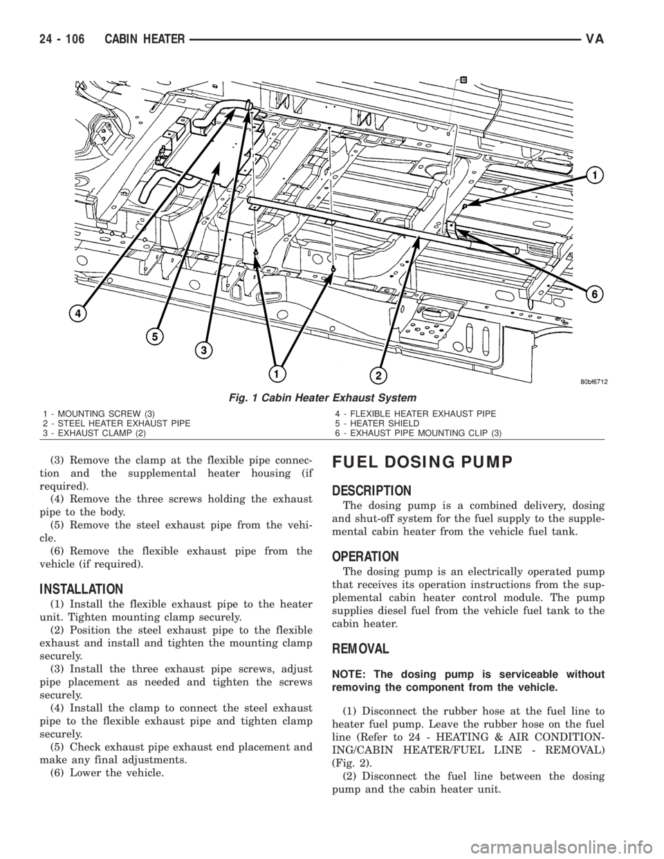
(2) Remove the exhaust clamp at the flexible pipe
and steel pipe connection (Fig. 1).
VACABIN HEATER 24 - 105
Page 2143 of 2305
(3) Remove the clamp at the flexible pipe connec-
tion and the supplemental heater housing (if
required).
(4) Remove the three screws holding the exhaust
pipe to the body.
(5) Remove the steel exhaust pipe from the vehi-
cle.
(6) Remove the flexible exhaust pipe from the
vehicle (if required).
INSTALLATION
(1) Install the flexible exhaust pipe to the heater
unit. Tighten mounting clamp securely.
(2) Position the steel exhaust pipe to the flexible
exhaust and install and tighten the mounting clamp
securely.
(3) Install the three exhaust pipe screws, adjust
pipe placement as needed and tighten the screws
securely.
(4) Install the clamp to connect the steel exhaust
pipe to the flexible exhaust pipe and tighten clamp
securely.
(5) Check exhaust pipe exhaust end placement and
make any final adjustments.
(6) Lower the vehicle.
FUEL DOSING PUMP
DESCRIPTION
The dosing pump is a combined delivery, dosing
and shut-off system for the fuel supply to the supple-
mental cabin heater from the vehicle fuel tank.
OPERATION
The dosing pump is an electrically operated pump
that receives its operation instructions from the sup-
plemental cabin heater control module. The pump
supplies diesel fuel from the vehicle fuel tank to the
cabin heater.
REMOVAL
NOTE: The dosing pump is serviceable without
removing the component from the vehicle.
(1) Disconnect the rubber hose at the fuel line to
heater fuel pump. Leave the rubber hose on the fuel
line (Refer to 24 - HEATING & AIR CONDITION-
ING/CABIN HEATER/FUEL LINE - REMOVAL)
(Fig. 2).
(2) Disconnect the fuel line between the dosing
pump and the cabin heater unit.
Fig. 1 Cabin Heater Exhaust System
1 - MOUNTING SCREW (3)
2 - STEEL HEATER EXHAUST PIPE
3 - EXHAUST CLAMP (2)4 - FLEXIBLE HEATER EXHAUST PIPE
5 - HEATER SHIELD
6 - EXHAUST PIPE MOUNTING CLIP (3)
24 - 106 CABIN HEATERVA
Page 2144 of 2305
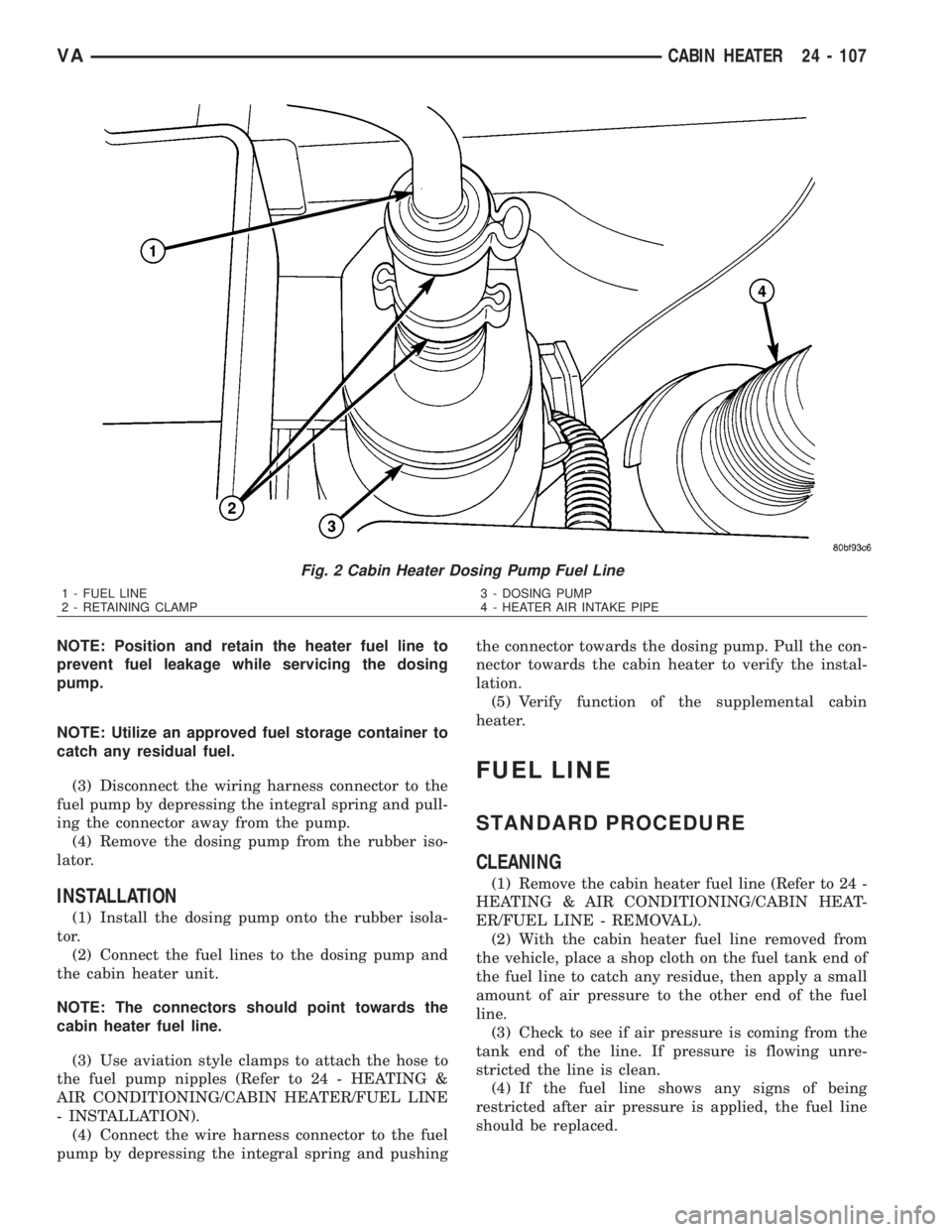
NOTE: Position and retain the heater fuel line to
prevent fuel leakage while servicing the dosing
pump.
NOTE: Utilize an approved fuel storage container to
catch any residual fuel.
(3) Disconnect the wiring harness connector to the
fuel pump by depressing the integral spring and pull-
ing the connector away from the pump.
(4) Remove the dosing pump from the rubber iso-
lator.
INSTALLATION
(1) Install the dosing pump onto the rubber isola-
tor.
(2) Connect the fuel lines to the dosing pump and
the cabin heater unit.
NOTE: The connectors should point towards the
cabin heater fuel line.
(3) Use aviation style clamps to attach the hose to
the fuel pump nipples (Refer to 24 - HEATING &
AIR CONDITIONING/CABIN HEATER/FUEL LINE
- INSTALLATION).
(4) Connect the wire harness connector to the fuel
pump by depressing the integral spring and pushingthe connector towards the dosing pump. Pull the con-
nector towards the cabin heater to verify the instal-
lation.
(5) Verify function of the supplemental cabin
heater.
FUEL LINE
STANDARD PROCEDURE
CLEANING
(1) Remove the cabin heater fuel line (Refer to 24 -
HEATING & AIR CONDITIONING/CABIN HEAT-
ER/FUEL LINE - REMOVAL).
(2) With the cabin heater fuel line removed from
the vehicle, place a shop cloth on the fuel tank end of
the fuel line to catch any residue, then apply a small
amount of air pressure to the other end of the fuel
line.
(3) Check to see if air pressure is coming from the
tank end of the line. If pressure is flowing unre-
stricted the line is clean.
(4) If the fuel line shows any signs of being
restricted after air pressure is applied, the fuel line
should be replaced.
Fig. 2 Cabin Heater Dosing Pump Fuel Line
1 - FUEL LINE
2 - RETAINING CLAMP3 - DOSING PUMP
4 - HEATER AIR INTAKE PIPE
VACABIN HEATER 24 - 107
Page 2145 of 2305
(5) Install the cabin heater fuel line (Refer to 24 -
HEATING & AIR CONDITIONING/CABIN HEAT-
ER/FUEL LINE - INSTALLATION).
(6) Verify function of the cabin heater.
REMOVAL
(1) Raise and support the vehicle. Take note of the
location of the flexible section of the cabin heater
exhaust tube.
NOTE: Have an approved fuel holding device ready
to capture any diesel fuel that drains from the fuel
line or cabin heater unit.
(2) Remove clamps on dosing pump end of fuel line
and separate line from the pump (Fig. 3).
24 - 108 CABIN HEATERVA
Page 2147 of 2305
(7) With the DRBIIItscan tool in Cabin Heater,
select System Tests and Dosing Pump Prime. Allow
the dosing pump to run for the full 45 second cycle
time. When the 45 second cycle is complete, press
Page Back on the DRBIIItscan tool key pad to exit
the Dosing Pump Prime. The Dosing Pump Priming
procedure is now complete.
HEATER UNIT
REMOVAL
HEATER UNIT
WARNING: Do not operate the diesel supplemental
cabin heater in an enclosed area such as a garage
that does not have exhaust ventilation facilities.
Always vent the cabin heater exhaust when operat-
ing the cabin heater. Allow the diesel supplemental
cabin heater to cool before performing any service
procedures to the cabin heater. Verify that all diesel
supplemental cabin heater fuel lines are securely
fastened to their respective components before per-
forming any service procedures to the cabin heater.
Failure to follow these warnings may result in pos-
sible personal injury or death.
(1) Raise and support the vehicle. Take note of the
location of the flexible section of the cabin heater
exhaust tube.
(2) Drain the engine cooling system (Refer to 7 -
COOLING - STANDARD PROCEDURE - DRAINING
COOLING SYSTEM).
(3) Carefully open one hose to the underbody tube
assembly and drain the remaining coolant. A salvage
hose is a good idea to control the residual coolant, as
flow will occur from both the cabin heater and the
hose and tube assemblies.
(4) Remove the second hose from the underbody
hose and tube assembly.
(5) Loosen the hose and tube assembly from the
toe-board crossmember at two locations.
(6) Disconnect the electrical connector from the
body harness near the toe-board crossmember and
rail.
(7) Remove the wiring harness from the toe-board
crossmember (Refer to 24 - HEATING & AIR CON-
DITIONING/CABIN HEATER/HEATER UNIT -
REMOVAL - WIRE HARNESS).
(8) Open the fuel filler cap. Disconnect the rubber
fuel hose between the body tube assembly and the
fuel pump nipple at the body tube joint. A minimal
amount of fuel may flow from the open port.
NOTE: Utilize an approved fuel storage container to
catch any residual fuel.(9) Loosen the two fasteners at the rail. Take care
to notice that the exhaust tube bracket tab is on top
of the heater bracket and that there are two spacer
washers installed between the rubber grommets.
(10) Remove the flexible section of the cabin
heater exhaust tube from the exhaust tube by loos-
ening the clamp. Remove the hose from the exhaust
tube. Removal of the rail tube assembly may aid in
this service operation (Refer to 24 - HEATING & AIR
CONDITIONING/CABIN HEATER/EXHAUST TUBE
- REMOVAL).
(11) Remove seat hex nut at the heater mounting
flange to crossmember.
(12) Loosen the remaining fasteners which mount
the exhaust tube assembly to the vehicle.
(a) Install a suitable support device under the
cabin heater and secure the cabin heater to the
support.
(13) Loosen the remaining three fasteners to the
crossmembers.
(14) Remove the loosened fasteners that support
the cabin heater while supporting the weight of the
heater.
(15) Swing the cabin heater mounting bracket
from between the exhaust bracket and rail mounting
location. Drain any residual coolant from the cabin
heater.
(16) Remove the cabin heater from the vehicle.
WIRE HARNESS
(1) Raise and support the vehicle while taking note
of the location of the flexible exhaust tube section.
(2) Disconnect the cabin heater wire harness con-
nector from the vehicle wiring harness.
(3) Disconnect the cabin heater wire harness con-
nector from the dosing pump.
(4) Disconnect the two cabin heater wire harness
connectors from the cabin heater controller.
(5) Remove two wiring harness retainers from the
underbody.
(6) Remove two wiring harness retainers from the
cabin heater shield.
(7) Carefully route the cabin heater wire harness
out the left side between the heater unit and the
heater shield.
INSTALLATION
HEATER UNIT
(1) Install the cabin heater mounting bracket
between the exhaust bracket and the rail mounting
location.
(2) Support the cabin heater and install the fasten-
ers that secure the cabin heater to the mounting
bracket.
(3) Install the three fasteners to the crossmem-
bers. Tighten the M6 fasteners to 7 N´m (62 in. lbs.).
24 - 110 CABIN HEATERVA
Page 2148 of 2305
(4) Position the two spacer washers between the
body and the rubber grommets for the two mounting
points on the rail.
(5) Tighten the remaining M6 fasteners to 7 N´m
(62 in. lbs.) and the M8 fasteners to 23 N´m (17 ft.
lbs.) which mount the exhaust tube assembly to the
vehicle.
(6) Install the seat hex nut at the heater mounting
flange to the crossmembers. Tighten the nut to 60
N´m (44 ft. lbs.)
(7) Install the flexible section of the cabin heater
exhaust tube to the exhaust tube. Tighten the M6
bolt of the clamp securley. Install the hose to the
exhaust tube.
(8) Tighten the two M8 fasteners at the rail to 23
N´m (17 ft. lbs.). Taking care so that the exhaust
tube bracket tab is on the top of the heater bracket.
(9) Install the wiring harness (Refer to 24 - HEAT-
ING & AIR CONDITIONING/CABIN HEATER/
HEATER UNIT - INSTALLATION - WIRE
HARNESS).
(10) Tighten the hose and tube assembly to the
toe-board crossmember at two locations.
(11) Install the second hose to the underbody hose
and tube assembly.
(12) Connect the rubber fuel hose between the
body tube assembly and the fuel pump nipple at the
body tube joint. Close the fuel fill cap.
(13) Remove the cabin heater support device from
under the vehicle.
(14) Lower the vehicle.
(15) Fill the engine cooling system (Refer to 7 -
COOLING - STANDARD PROCEDURE - COOLING
SYSTEM FILL).
(16) Verify function of the heater unit.
WIRE HARNESS
(1) Carefully route the cabin heater wire harness
from the left side between the heater unit and the
heater shield.
(2) Install the two wiring harness retainers to the
cabin heater shield.
(3) Route the wiring harness along the underside
of the vehicle and install the two wiring harness
retainers to the underbody.
(4) Connect the two cabin heater wire harness con-
nectors to the cabin heater controller.
(5) Connect the cabin heater wire harness to the
dosing pump.
(6) Connect the cabin heater wire harness connec-
tor to the vehicle wiring harness.
(7) Lower the vehicle.
(8) Verify function of the heater unit.
INLET HOSE
REMOVAL
NOTE: The air intake tube for the supplemental
cabin heater is part of an assembly that includes
the heater cooling intake and return pipes. If the
cabin heater air intake tube requires removal or
replacement the entire cabin heater assembly will
require removal or replacement.
(1) Drain the engine cooling system (Refer to 7 -
COOLING - STANDARD PROCEDURE - DRAINING
COOLING STSTEM).
(2) Remove clamps from the cabin heater tubes at
the lower heater port and the lower EGR connector
which are located under the hood.
(3) Remove the retaining clamp at the cabin
heater air intake muffler connection (Refer to 24 -
HEATING & AIR CONDITIONING/CABIN HEAT-
ER/INLET MUFFLER - REMOVAL).
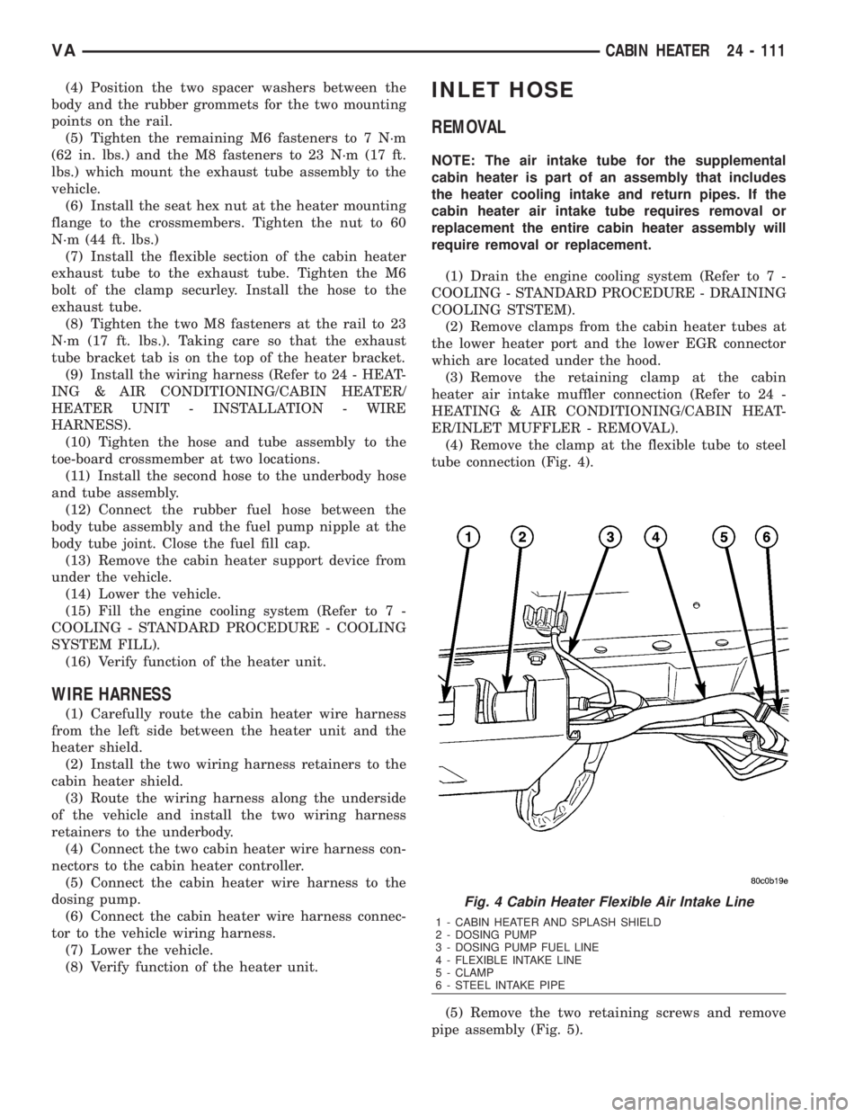
(4) Remove the clamp at the flexible tube to steel
tube connection (Fig. 4).
(5) Remove the two retaining screws and remove
pipe assembly (Fig. 5).
Fig. 4 Cabin Heater Flexible Air Intake Line
1 - CABIN HEATER AND SPLASH SHIELD
2 - DOSING PUMP
3 - DOSING PUMP FUEL LINE
4 - FLEXIBLE INTAKE LINE
5 - CLAMP
6 - STEEL INTAKE PIPE
VACABIN HEATER 24 - 111