2006 MERCEDES-BENZ SPRINTER air condition
[x] Cancel search: air conditionPage 2153 of 2305
EXHAUST GAS RECIRCULATION
TABLE OF CONTENTS
page page
EXHAUST GAS RECIRCULATION
DESCRIPTION..........................4
VA LV E
DESCRIPTION..........................5
OPERATION............................6REMOVAL.............................6
INSTALLATION..........................6
VALVE COOLER
DESCRIPTION..........................6
EXHAUST GAS RECIRCULA-
TION
DESCRIPTION
The EGR system can provide up to 35% exhaust
gas recirculation. The EGR operates during all
engine speed and load conditions. At wide open throt-
tle, it provides a 5% recirculation rate. The EGR
shuts down during high engine idle to avoid carbon
build up on the valve. The EGR also deactivates if
the EGR temperature is too high. The EGR also has
a self cleaning function that opens and closes twice
after the engine has been shut off to eliminate soot
deposits.
Apart from the charge air distribution manifold
and the mixing chamber, the intake manifold also
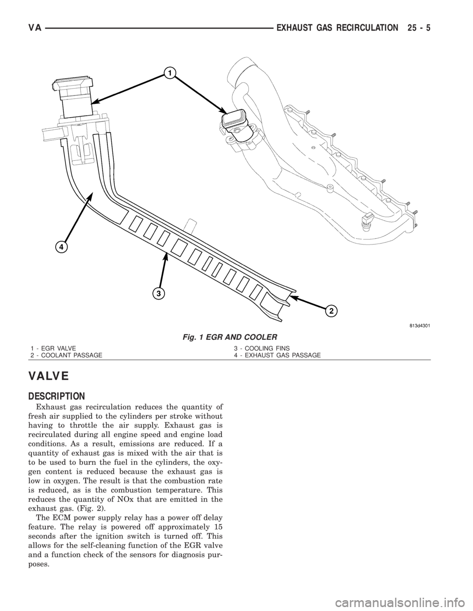
includes a finned EGR cooler. Coolant flows through
the cooler to reduce the temperature of the recircu-
lated gas after it was cooled by running through the
cylinder head. The management of this temperature
significantly reduces emissions (Fig. 1).
25 - 4 EXHAUST GAS RECIRCULATIONVA
Page 2154 of 2305
VA LV E
DESCRIPTION
Exhaust gas recirculation reduces the quantity of
fresh air supplied to the cylinders per stroke without
having to throttle the air supply. Exhaust gas is
recirculated during all engine speed and engine load
conditions. As a result, emissions are reduced. If a
quantity of exhaust gas is mixed with the air that is
to be used to burn the fuel in the cylinders, the oxy-
gen content is reduced because the exhaust gas is
low in oxygen. The result is that the combustion rate
is reduced, as is the combustion temperature. This
reduces the quantity of NOx that are emitted in the
exhaust gas. (Fig. 2).
The ECM power supply relay has a power off delay
feature. The relay is powered off approximately 15
seconds after the ignition switch is turned off. This
allows for the self-cleaning function of the EGR valve
and a function check of the sensors for diagnosis pur-
poses.
Fig. 1 EGR AND COOLER
1 - EGR VALVE 3 - COOLING FINS
2 - COOLANT PASSAGE 4 - EXHAUST GAS PASSAGE
VAEXHAUST GAS RECIRCULATION 25 - 5
Page 2158 of 2305
INDEX
ABS INDICATOR.......................8J-9ACCELERATOR PEDAL POSITION SENSOR. . . 14-32
ACCESSORY SWITCH BEZEL............23-56
ADR INDICATOR.....................8J-10
AIR CLEANER ELEMENT................9-21
AIR CLEANER HOUSING................9-21
AIR FILTER ....................24-45, 24-58
AIR OUTLET TEMPERATURE SENSOR....24-16
AIR OUTLETS.......................24-45
AIRBAG CONTROL MODULE.............8O-8
AIRBAG INDICATOR...................8J-11
ALB CONTROLLER....................5-16
ALB LEVER..........................5-16
AMBIENT TEMPERATURE INDICATOR.....8J-11
AMBIENT TEMPERATURE SENSOR.......24-17
ANTENNA BODY & CABLE..............8A-1
ARMREST..........................23-79
ASH RECEIVER......................23-57
ASH RECEIVER / CIGAR LIGHTER LAMP
UNIT..............................8L-30
ASSIST HANDLE.....................23-71
AUDIO..............................8A-1
AUTOMATIC TRANSMISSION NAG1 -
SERVICE INFORMATION................21-3
A - PILLAR TRIM.....................23-70
A / C CLUTCH RELAY.................24-24
A / C COMPRESSOR CLUTCH COIL.......24-12
A / C COMPRESSOR CLUTCH............24-8
A / C COMPRESSOR..................24-66
A / C CONDENSER COVER.............24-52
A / C CONDENSER FAN RELAY..........24-26
A / C CONDENSER HOUSING...........24-52
A / C CONDENSER....................24-69
A / C CONTROL MODULE..............24-28
A / C DISCHARGE LINE................24-71
A / C EVAPORATOR COVER.............24-55
A / C EVAPORATOR HOUSING...........24-55
A / C EVAPORATOR...................24-72
A / C EXPANSION VALVE...............24-73
A / C HEATER CONTROL...............24-12
A / C HIGH PRESSURE SWITCH.........24-30
A / C LOW PRESSURE SWITCH.........24-32
A / C PRESSURE TRANSDUCER.........24-14
BACKLITE - BULKHEAD TRIM PANEL.....23-84
BACKUP LAMP BULB..................8L-5
BASECOAT / CLEARCOAT FINISH........23-77
BATTERY CABLES....................8F-14
BATTERY HOLDDOWN.................8F-13
BATTERY SYSTEM.....................8F-1
BATTERY TRAY......................8F-16
BATTERY............................8F-6
BEARINGS - DIFFERENTIAL CASE.........3-38
BEARING / SEAL - AXLE HUB............3-28
BEARING / SEAL - AXLE................3-24
BELT TENSIONERS.....................7-5
BLOWER MOTOR RELAY...............24-33
BLOWER MOTOR RESISTOR............24-17
BLOWER MOTOR SWITCH........24-19, 24-35
BLOWER MOTOR...............24-47, 24-58
BODY...............................23-1
BOOST PRESSURE SENSOR............14-33
BRAKE INDICATOR...................8J-12
BRAKE LAMP SWITCH.................8L-6
BRAKE LINES.........................5-8
BRAKE PADS / SHOES...................5-8
BRAKE WEAR INDICATOR..............8J-13
BRAKES - ABS........................5-30
BRAKES - BASE........................5-2
BRAKE / PARK LAMP BULB.............8L-7
BULKHEAD TRIM PANEL...............23-72
BUMPERS...........................13-1
BUSHINGS............................2-3
B - PILLAR TRIM.....................23-71
CABIN HEATER.....................24-104
CABLE TENSIONER....................5-24
CABLE..............................8P-2
CABLES.............................5-24
CAMSHAFT POSITION SENSOR..........14-33
CAMSHAFT(S)........................9-28
CARGO LAMP SWITCH................8L-31
CARGO / DOME LAMP BULB............8L-30
CARGO / DOME LAMP UNIT............8L-31
CARPETS AND FLOOR MATS...........23-72
CATALYTIC CONVERTER
................11-3
CENTER BEARING
......................3-9
CENTER HIGH MOUNTED STOP LAMP BULB. . . 8L-8CENTER HIGH MOUNTED STOP LAMP UN.....8L-8
CENTER ROLLER ARM
................23-36CENTER TRACK......................23-37
CENTRAL TIMER MODULE..............8E-1
CHARGE AIR COOLER AND PLUMBING....11-4
CHARGING INDICATOR................8J-14
CHARGING SYSTEM..................8F-17
CHECK VALVE.......................8R-11
CHECK.......................23-13, 23-23
CHIME / BUZZER......................8B-1
CIGAR LIGHTER OUTLET............8W-97-1
CIRCUIT BREAKER.................8W-97-2
CLEARANCE LAMP BULB...............8L-9
CLEARANCE LAMP UNIT................8L-9
CLOCK.............................8J-14
CLOCKSPRING......................8O-12
CLUSTER BEZEL.....................23-55
COLUMN............................19-4
CONNECTOR.......................Intro.-9
CONNECTOR/GROUND/SPLICE
LOCATION........................8W-91-1
CONTROLLER ANTILOCK BRAKE.........8E-3
COOLANT LEVEL SENSOR...............7-13
COOLANT LOW INDICATOR.............8J-15
COOLANT............................7-9
COOLING.............................7-1
COWL TRIM........................23-73
CRANKCASE VENTILATION BREATHER......25-2
CRANKCASE VENTILATION HEATER.......25-1
CRANKSHAFT OIL SEAL - FRONT.........9-42
CRANKSHAFT OIL SEAL - REAR..........9-41
CRANKSHAFT POSITION SENSOR........14-35
CRANKSHAFT........................9-39
CUP HOLDER........................23-57
CYLINDER HEAD COVER(S).............9-33
CYLINDER HEAD......................9-22
DAYTIME RUNNING LAMP RELAY.......8L-10
DEFROSTER DUCTS..................24-47
DIFFERENTIAL........................3-31
DIODE............................Intro.-9
DISC BRAKE CALIPER ADAPTER.........5-14
DISC BRAKE CALIPERS.................5-11
DOME LAMP / INTRUSION SENSOR
BULB..............................8L-33
DOME LAMP / INTRUSION SENSOR......8L-33
DOME / READING LAMP BULB..........8L-32
DOME / READING LAMP UNIT..........8L-32
DOOR GLASS............23-15, 23-30, 23-46
DOOR JAMB SWITCH.................8L-34
DOOR LOCK MOTOR...................8N-1
DOOR OPENING SEALS................23-90
DOOR........................23-14, 23-23
DRIVE BELTS..........................7-5
DRIVER AIRBAG.....................8O-16
DRIVER HEATED SEAT SWITCH.........8G-11
D - PILLAR TRIM.....................23-73
ELECTRIC COOLANT PUMP.............24-75
ELECTRICAL.........................5-30
ELECTROHYDRAULIC UNIT............21-105
ENGINE BLOCK HEATER................7-14
ENGINE BLOCK.......................9-37
ENGINE CONTROL MODULE.............8E-3
ENGINE COOLANT TEMP SENSOR........7-15
ENGINE COOLANT THERMOSTAT.........7-16
ENGINE CRADLE CROSSMEMBER........13-8
ENGINE TEMPERATURE GAUGE.........8J-15
ENGINE..............................9-2
ENTRY / EXIT LAMP BULB.............8L-34
ENTRY / EXIT LAMP UNIT..............8L-35
ESP INDICATOR......................8J-16
EVAPORATOR TEMPERATURE
SENSOR......................24-19, 24-37
EXHAUST GAS RECIRCULATION..........25-4
EXHAUST MANIFOLD..................9-68
EXHAUST PIPE.......................11-3
EXHAUST SYSTEM....................11-1
EXHAUST TUBE.....................24-105
EXTERIOR HANDLE.......23-16, 23-31, 23-35
FAN DRIVE VISCOUS CLUTCH...........7-17
FASTENER IDENTIFICATION...........Intro.-3
FASTENER USAGE...................Intro.-6
FINESSE SANDING / BUFFING & POLISH . . 23-78
FLOOR DISTRIBUTION DUCTS..........24-47
FLUID AND FILTER..................21-131
FLUID CAPACITIES.....................0-5
FLUID COOLER TUBE
.................19-13
FLUID FILL / CHECK LOCATIONS
..........0-5
FLUID RESERVOIR
....................5-15
FLUID TYPES
..........................0-1
FLYWHEEL
...........................9-43FOG LAMP BULB.....................8L-10
FOG LAMP RELAY....................8L-11
FOG LAMP SWITCH...................8L-12
FRAME..............................13-3
FREEWHEELING CLUTCH.............21-135
FRONT BUMPER - STEPS...............13-2
FRONT DOOR INNER BELT
WEATHERSTRIP.....................23-90
FRONT DOOR OUTER BELT
WEATHERSTRIP.....................23-90
FRONT FASCIA.......................13-2
FRONT LAMP UNIT...................8L-13
FRONT POSITION LAMP BULB..........8L-14
FRONT SEAT BELT & RETRACTOR.......8O-20
FRONT SEAT BELT BUCKLE............8O-23
FRONT TURN / PARK / SIDE MARKER
LAMP BULB.........................8L-15
FRONT WHEEL SPEED SENSOR..........5-31
FRONT...............................2-1
FUEL DELIVERY.......................14-6
FUEL DOSING PUMP.................24-106
FUEL DRAIN TUBES..................14-10
FUEL FILL DOOR.....................23-48
FUEL FILTER CLOGGED INDICATOR......8J-17
FUEL FILTER........................14-10
FUEL GAUGE........................8J-17
FUEL INJECTOR.......................14-35
FUEL LEVEL SENDING UNIT / SENSOR....14-28
FUEL LINE.........................24-107
FUEL LINES.........................14-11
FUEL PRESSURE SENSOR.............14-39
FUEL PRESSURE SOLENOID............14-40
FUEL PUMP MODULE.................14-18
FUEL PUMP.........................14-13
FUEL QUANTITY CONTROL VALVE.......14-21
FUEL RAIL PRESSURE SENSOR.........14-12
FUEL RAIL..........................14-22
FUEL SYSTEM........................14-1
FUEL TANK.........................14-23
FUEL TEMPERATURE SENSOR..........14-42
FUSE BLOCK #1...................8W-97-2
FUSE BLOCK #2...................8W-97-3
GAP AND FLUSH.....................23-91
GEAR SELECTOR INDICATOR...........8J-18
GEAR...............................19-7
GEARSHIFT CABLE..................21-138
GEAR - PINION / RING.................3-41
GENERATOR DECOUPLER PULLEY.......8F-19
GENERATOR........................8F-18
GLOVE BOX.........................23-58
GLOW PLUG RELAY....................8I-1
GLOW PLUG..........................8I-1
GRILLE............................23-48
HCU (HYDRAULIC CONTROL UNIT).......5-36
HEADLAMP LEVELING MOTOR..........8L-16
HEADLAMP LEVELING SWITCH.........8L-17
HEADLINER.........................23-73
HEADREST..........................23-79
HEATED GLASS.......................8G-1
HEATED MIRRORS....................8G-9
HEATED SEAT ELEMENT...............8G-12
HEATED SEAT RELAY.................8G-12
HEATED SEAT SENSOR................8G-13
HEATED SEATS ......................8G-10
HEATER CORE.......................24-76
HEATER UNIT......................24-110
HEATING & AIR CONDITIONING..........24-1
HIGH BEAM HEADLAMP BULB..........8L-18
HIGH BEAM INDICATOR...............8J-19
HINGE..................23-17, 23-32, 23-51
HOISTING............................0-5
HOLDING CLUTCH B1................21-143
HOLDING CLUTCH B2................21-148
HOLDING CLUTCHES.................21-141
HOOD.............................23-51
HORN SWITCH.......................8H-1
HORN..............................8H-1
HOSES.............................19-14
HUB / BEARING........................2-4
HVAC HOUSING......................24-48
HYDRAULIC / MECHANICAL..............5-5
IGNITION CONTROL....................8I-1
INLET HOSE........................24-111
INPUT CLUTCH K1
...................21-92
INPUT CLUTCH K2
...................21-97
INPUT CLUTCH K3
..................21-102
INPUT CLUTCHES
....................21-90
INPUT SPEED SENSORS
..............21-153
VAINDEX 1
Description Group-Page Description Group-Page Description Group-Page
Page 2166 of 2305
1.0 INTRODUCTION
The procedures contained in this manual include
all of the specifications, instructions, and graphics
needed to diagnose NAG1 Electronic Automatic
Transmission and Shift Lever Assembly problems.
The diagnostics in this manual are based on the
failure condition or symptom being present at the
time of diagnosis.
When repairs are required, refer to the appropri-
ate volume of the service information for the proper
removal and repair procedure.
READ THIS MANUAL BEFORE TRYING TO
DIAGNOSE A VEHICLE TROUBLE CODE.
Diagnostic procedures change every year. New
diagnostic systems may be added and/or carryover
systems may be enhanced. It is recommended that
you review the entire manual to become familiar
with all new and changed diagnostic procedures.
1.1 SYSTEM COVERAGE
This diagnostic procedures manual covers all
Sprinter (VA) equipped with a NAG1 Automatic
Transmission.
1.2 SIX -STEP TROUBLESHOOTING
PROCEDURE
Diagnosis of the NAG1 electronic transmission is
done in six basic steps:
Verification of complaint
Verification of any related symptoms
Symptom analysis
Problem isolation
Repair of isolated problem
Verification of proper operation
2.0 IDENTIFICATION OF
SYSTEM
The NAG1 Transmission family can be identified
by the presence of a 13 pin electrical connector, with
a bayonet lock on the right hand side of the trans-
mission. The connector is oriented horizontally.
3.0 SYSTEM DESCRIPTION AND
FUNCTIONAL OPERATION
3.1 GENERAL DESCRIPTION
The NAG1 electronic transmission is an electron-
ically controlled five speed transmission with a
controlled slip torque converter. The NAG1 elec-tronic transmission is a conventional transmission
in that it uses hydraulically applied clutches to shift
a planetary gear train. However, the electronic
control system replaces many of the mechanical and
hydraulic components used in conventional trans-
mission valve bodies.
The ratios for the gear stages are obtained by 3
planetary gear sets. Fifth Gear is designed as an
Overdrive with a high speed ratio. The gears are
actuated electronically/hydraulically. The electronic
control system enables precise adaptation of pres-
sures to the respective operating conditions and to
the engine output during a shift phase, which
results in a significant improvement in shift qual-
ity.
3.2 FUNCTIONAL OPERATION
The NAG1 electronic transmission has a fully
adaptive control system. The system performs its
functions based on continuous real-time sensor and
switch feedback information. In addition the TCM
receives information from the Shift Lever Assembly,
ECM (engine management) and ABS (chassis sys-
tems) controllers over the CAN bus. The CAN bus is
a high speed communication bus that allows real
time control capability between various controllers.
Most messages are sent every 20 milliseconds, this
means critical information can be shared between
the Transmission, Shifter, Engine and ABS control-
lers. The CAN bus is a two wire bus with aCAN C
Bus (+) circuitand aCAN C Bus (-) circuit. The
CAN bus uses a twisted pair of wires in the harness
to reduce the potential of radio and noise interfer-
ence. The CAN bus also uses a 120 ohm terminating
resistor in both the ECM and Sentry Key Remote
Entry Module (SKREEM) modules. The module
terminating resistance is measured across both
CAN bus circuits at the ECM or SKREEM module.
The control system automatically adapts to
changes in engine performance, vehicle speed, and
transmission temperature variations to provide
consistent shift quality. The control system ensures
that clutch operation during upshifting and down-
shifting is more responsive without increased
harshness. The TCM controls the actuation of sole-
noid valves for modulating shift pressure and gear
change. The required pressure level is calculated
from the load condition, engine speed. Power for the
transmission system is supplied through the Trans-
mission Relay. The TCM is located in the under the
drivers seat of the vehicle.
The Transmission Control Module (TCM) contin-
uously checks for electrical problems, mechanical
problems, and some hydraulic problems. When a
problem is sensed, the TCM stores a diagnostic
trouble code (DTC). Some of these codes cause the
transmission to go into9limp-in9or9default9mode.
1
GENERAL INFORMATION
Page 2169 of 2305
3.2.5 TRANSMISSION OPERATION AND
SHIFT SCHEDULING
The transmission covered in this manual has
unique shift schedules depending on the tempera-
ture of the transmission oil. The transmission oil
temperature has a decisive effect on the shift qual-
ity of the transmission. The shift schedule is modi-
fied to extend the life of the transmission while
operating under extreme conditions and to improve
driver comfort by modifying shift schedules.
The transmission oil temperature is measured
with a Temperature Sensor on the NAG1 transmis-
sion. The Temperature Sensor is an integral com-
ponent of the Transmission Solenoid assembly. If
the Temperature Sensor is causing a problem, a
DTC will be set in the TCM.
The Transmission Temperature Sensor is wired in
series with the Park /Neutral (P/N) switch. The P/N
switch is also located in the transmission. The trans-
mission temperature is only read by the TCM when
the P/N switch closes while in the R, D position.
When the shifter lever is in the park or neutral
position, the P/N switch opens and the temperature
being displayed is Engine temperature.
AutoStick Feature (If equipped)
This feature allows the driver to manually shift the
transaxle when the shift lever is moved sideways to
the (+ / -) in position D to adjust the shift range.
3.2.6 TRANSMISSION ADAPTIVES -
INITIALIZE AND STORE
Initialize Adaptive -This TCM function should be
used when a new transmission has been placed in
the vehicle. This command will reset the TCM
adaptive to the factory setting.
Store Adaptive -This command should be used
after the vehicle has been test driven by the tech-
nician to store any learned adaptive changes that
occurred during the test drive. During normal op-
eration adaptive are updated every 10 minutes.
Using this command the latest adaptive will be
written to the TCM immediately.
3.3 DIAGNOSTIC TROUBLE CODES
Diagnostic trouble codes (DTC's) are codes stored
by the Transmission Control Module (TCM) and the
Shift Lever Assembly Module (SLA) to help diag-
nose Transmission and Shifter problems. They are
viewed using the DRBIIItscan tool.
Always begin by performing a visual inspection of
the wiring, connectors, cooler lines and the trans-
mission. Any obvious wiring problems or leaks
should be repaired prior to performing any diagnos-
tic test procedures. Some engine driveability prob-lems can be misinterpreted as a transmission prob-
lem. Ensure that the engine is running properly
and that no ECM DTC's are present that could
cause a transmission complaint.
If there is a communication K-ABS,Shifter or
K-TCM circuit problem, trouble codes will not be
accessible until the problem is fixed. The DRBIIIt
will display an appropriate message. The following
is a possible list of causes for a bus problem:
± open or short to ground/battery in K line
circuit.
± internal failure of any module or component
connected to the K line circuit
Each diagnostic trouble code is diagnosed by
following a specific testing sequence. The diagnostic
test procedures contain step-by-step instructions
for determining the cause of a transmission diag-
nostic trouble code. Possible sources of the code are
checked and eliminated one by one. It is not neces-
sary to perform all of the tests in this book to
diagnose an individual code. These tests are based
on the problem being present at the time that the
test is run.
If the TCM records a DTC that will adversely
affect the vehicles transmission, it will request (via
the communication bus) that the ECM illuminate
the Malfunction Indicator Lamp (MIL). All trans-
mission DTC's will be stored in the TCM.
3.3.1 ACTIVE (HARD) CODE
Any Diagnostic Trouble Code (DTC) that is set
whenever the system or component is monitored is
an Active code. This means that the problem is
there every time the TCM checks that system or
component. Some codes will set immediately at
start up and others will require a road test under
specific conditions to set the DTC. It must be
determined if a code is Active (repeatable) or Stored
(Intermittent) before attempting diagnosis.
3.3.2 STORED (INTERMITTENT) CODE
A diagnostic trouble code that is not there every
time the TCM checks the circuit or function is a
Stored (Intermittent) code. Problems that come and
go like this are the most difficult to diagnose, they
must be looked for under the specific conditions
that cause them. If the DTC is reset (after an
ignition cycle) the DTC will be set to Stored (Inter-
mittent) status. A DTC status can be9Active9or
9Stored9(Intermittent). Active is when the DTC is
present in the controller and the transmission is in
the particular mode of operation for that DTC.
Stored means that the DTC occurred at some point,
but is not currently present, or the conditions have
not been right to check for the presence of the
problem, when a DTC is classified as Stored (Inter-
mittent), no TCM reaction is required.
4
GENERAL INFORMATION
Page 2172 of 2305
²Disconnect the live test lead before disconnecting
the common test lead.
²When using the meter function, keep the
DRBIIItaway from spark plug or coil wires to
avoid measuring error from outside interference.
4.3 WARNINGS
4.3.1 VEHICLE DAMAGE WARNINGS
Before disconnecting any control module, make
sure the ignition is9lock9position. Failure to do so
could damage the module.
When testing voltage or continuity at any control
module, use the terminal side (not the wire end) of
the connector. Do not probe a wire through the
insulation: this will damage the wire and eventu-
ally cause the wire to fail because of corrosion.
Be careful when performing electrical tests so as
to prevent accidental shorting of terminals. Such
mistakes can damage fuses or components. Also, a
second DTC could be set, making diagnosis of the
original problem more difficult.
When replacing a blown fuse, it is important to
use only a fuse having the correct amperage rating.
The use of a fuse with a rating other than indicated
may result in a dangerous electrical system over-
load. If a properly rated fuse continues to blow, it
indicates a problem in the circuit that must be
corrected.
4.3.2 ROAD TESTING A COMPLAINT
VEHICLE
Some complaints will require a test drive as part
of the repair verification procedure. The purpose of
the test drive is to try to duplicate the diagnostic
DTC or symptom condition.
CAUTION: Before road testing a vehicle, be
sure that all components are reassembled.
During the test drive, do not try to read
DRBIIITscreen while in motion. Do not hang
the DRBIIITfrom the rear view mirror or
operate it yourself. Have an assistant
available to operate the DRBIIIT.
Road testing is an essential step in the diagnostic
process that must not be overlooked. Along with the
diagnostic information obtained from the DRBIIIt
Scan Tool and the original customer concern, the
road test helps verify the problem was current and
any repairs performed, fixed the vehicle correctly.
Always operate and observe the vehicle under ac-
tual driving conditions.
Just as important as the road test is, there are
preliminary inspections that should be performed
prior to the road test. Always check the fluid leveland condition before taking the vehicle on a road
test. Determine if the incorrect fluid is being used,
improper fluid will result in erratic transmission
operation.
Some of the conditions of incorrect fluid level are as
follows:
²Delayed engagement
²Poor shifting or erratic shifting
²Excessive noise
²Overheating
The next step is to verify that the shift linkage is
correctly adjusted. If the shift linkage is incorrectly
adjusted, a number of complaints can result.
The TCM monitors the Shift Lever Position (SLP)
continuously. If the linkage is incorrectly adjusted,
the TCM will sense a shift lever position that is not
correct for the gear chosen by the driver. This may
cause a DTC to be set.
The following complaints may also be the result of
an incorrectly adjusted or worn linkage:
²Delayed clutch engagement
²Erratic shifts
²Vehicle will drive in neutral
²Engine will not crank in park or neutral
²Gear shift linkage will be able to be shifted
without the key in the ignition
²Not able to remove the ignition key in park
²Parking pawl will not engage properly
The shift linkage should also be adjusted when
replacing the Transmission, repairing the valve
body, or when repairing any component between the
shift lever and the Transmission.
Some questions to ask yourself when performing
the road test are as follows:
²Is the complaint or concern what you think the
problem is, based on the drivers description of the
problem?
²Is the Transmission operating normally, or is
there a real problem?
²When does the problem occur?
²Is the problem only in one gear range?
²What temperature does the problem occur?
²Does the vehicle have to sit over night for the
problem to occur?
²Does the transmission go into Limp-in mode?
4.4.4 BULLETINS AND RECALLS
Always perform all Safety Recalls and Technical
Service Bulletins that are applicable to the prob-
lem.
7
GENERAL INFORMATION
Page 2173 of 2305
5.0 REQUIRED TOOLS AND
EQUIPMENT
> DRBIIIt(diagnostic read-out box) - DRBIIIt
must use the latest release level.
> Jumper wires
> Test Light
> Ohmmeter
> Voltmeter
6.0 GLOSSARY OF TERMS
6.1 ACRONYMS
ABSAntilock Braking system
A/CAir conditioner
A/DAnalog to Digital conversion
APPAccelerator Pedal Position
CANController Area Network (Vehicle
Bus System)
CKTCircuit
DLCData Link Connector
DRBIIItDiagnostic Readout Box
DTCDiagnostic Trouble Code
ECMDiesel Engine Controller
EMCCElectronically Modulated Converter
Clutch
IODIgnition off-draw
ISSInput Speed Sensor (N2 and N3)
KK line communication bus
LEDLight Emitting Diode
MILMalfunction Indicator LampOSSOutput Speed Sensor (derived from
the ABS controller)
PEMCCPartial Electronically Modulated
Converter Clutch
PWMPulse width modulated
SKREEMSentry Key Remote Entry Module
SLAShift Lever Assembly
SWSwitch
TCCTorque Converter Clutch
TCMTransmission Control Module
TPThrottle Position
TRDTorque Reduction
TTSTransmission Temperature Sensor
1-2/4-5
solenoidcontrols the shift into and out of
2nd gear or 5th gear.
V2-3 so-
lenoidcontrols the shift into and out of 3rd
gear
V3-4 so-
lenoidcontrols the shift into and out of 4th
gear
VTCC
solenoidis pulse width modulated and con-
trols the TCC clutch
Shift
Pressure
Solenoidis a pulse width modulated solenoid
and controls the hydraulic pressure
to the shift elements.
Modula-
tion
pressure
solenoidis a pulse width modulated solenoid
and controls the hydraulic system
pressure
6.2 DEFINITIONS
Driving cycle counter) -The starts since first set
counter indicates the number of driving cycles since
the first occurrence of an error.
8
GENERAL INFORMATION
Page 2175 of 2305
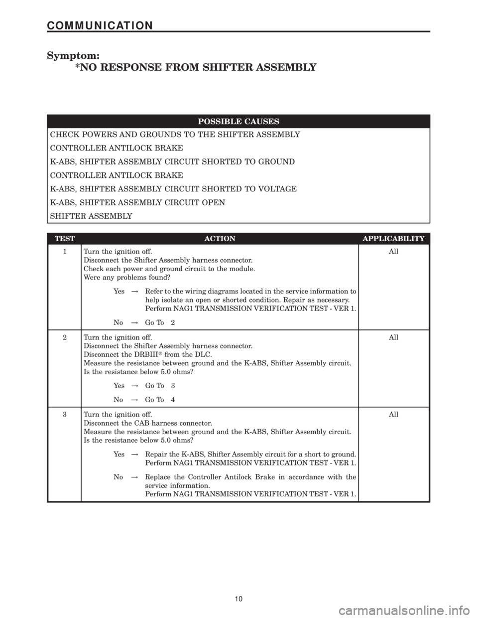
Symptom:
*NO RESPONSE FROM SHIFTER ASSEMBLY
POSSIBLE CAUSES
CHECK POWERS AND GROUNDS TO THE SHIFTER ASSEMBLY
CONTROLLER ANTILOCK BRAKE
K-ABS, SHIFTER ASSEMBLY CIRCUIT SHORTED TO GROUND
CONTROLLER ANTILOCK BRAKE
K-ABS, SHIFTER ASSEMBLY CIRCUIT SHORTED TO VOLTAGE
K-ABS, SHIFTER ASSEMBLY CIRCUIT OPEN
SHIFTER ASSEMBLY
TEST ACTION APPLICABILITY
1 Turn the ignition off.
Disconnect the Shifter Assembly harness connector.
Check each power and ground circuit to the module.
Were any problems found?All
Ye s!Refer to the wiring diagrams located in the service information to
help isolate an open or shorted condition. Repair as necessary.
Perform NAG1 TRANSMISSION VERIFICATION TEST - VER 1.
No!Go To 2
2 Turn the ignition off.
Disconnect the Shifter Assembly harness connector.
Disconnect the DRBIIItfrom the DLC.
Measure the resistance between ground and the K-ABS, Shifter Assembly circuit.
Is the resistance below 5.0 ohms?All
Ye s!Go To 3
No!Go To 4
3 Turn the ignition off.
Disconnect the CAB harness connector.
Measure the resistance between ground and the K-ABS, Shifter Assembly circuit.
Is the resistance below 5.0 ohms?All
Ye s!Repair the K-ABS, Shifter Assembly circuit for a short to ground.
Perform NAG1 TRANSMISSION VERIFICATION TEST - VER 1.
No!Replace the Controller Antilock Brake in accordance with the
service information.
Perform NAG1 TRANSMISSION VERIFICATION TEST - VER 1.
10
COMMUNICATION