2006 MERCEDES-BENZ SPRINTER oil filter
[x] Cancel search: oil filterPage 1802 of 2305
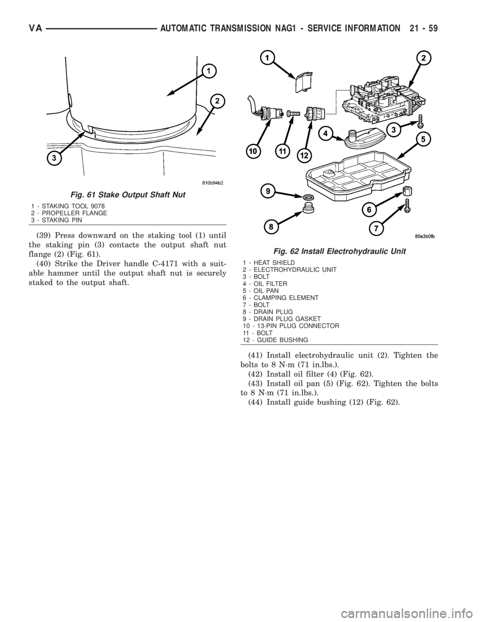
(39) Press downward on the staking tool (1) until
the staking pin (3) contacts the output shaft nut
flange (2) (Fig. 61).
(40) Strike the Driver handle C-4171 with a suit-
able hammer until the output shaft nut is securely
staked to the output shaft.
(41) Install electrohydraulic unit (2). Tighten the
bolts to 8 N´m (71 in.lbs.).
(42) Install oil filter (4) (Fig. 62).
(43) Install oil pan (5) (Fig. 62). Tighten the bolts
to 8 N´m (71 in.lbs.).
(44) Install guide bushing (12) (Fig. 62).
Fig. 61 Stake Output Shaft Nut
1 - STAKING TOOL 9078
2 - PROPELLER FLANGE
3 - STAKING PIN
Fig. 62 Install Electrohydraulic Unit
1 - HEAT SHIELD
2 - ELECTROHYDRAULIC UNIT
3 - BOLT
4 - OIL FILTER
5 - OIL PAN
6 - CLAMPING ELEMENT
7 - BOLT
8 - DRAIN PLUG
9 - DRAIN PLUG GASKET
10 - 13-PIN PLUG CONNECTOR
11 - BOLT
12 - GUIDE BUSHING
VAAUTOMATIC TRANSMISSION NAG1 - SERVICE INFORMATION 21 - 59
Page 1807 of 2305
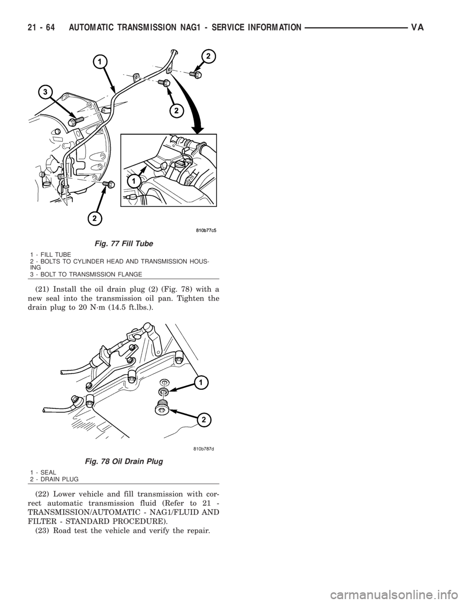
(21) Install the oil drain plug (2) (Fig. 78) with a
new seal into the transmission oil pan. Tighten the
drain plug to 20 N´m (14.5 ft.lbs.).
(22) Lower vehicle and fill transmission with cor-
rect automatic transmission fluid (Refer to 21 -
TRANSMISSION/AUTOMATIC - NAG1/FLUID AND
FILTER - STANDARD PROCEDURE).
(23) Road test the vehicle and verify the repair.
Fig. 77 Fill Tube
1 - FILL TUBE
2 - BOLTS TO CYLINDER HEAD AND TRANSMISSION HOUS-
ING
3 - BOLT TO TRANSMISSION FLANGE
Fig. 78 Oil Drain Plug
1 - SEAL
2 - DRAIN PLUG
21 - 64 AUTOMATIC TRANSMISSION NAG1 - SERVICE INFORMATIONVA
Page 1863 of 2305
REMOVAL
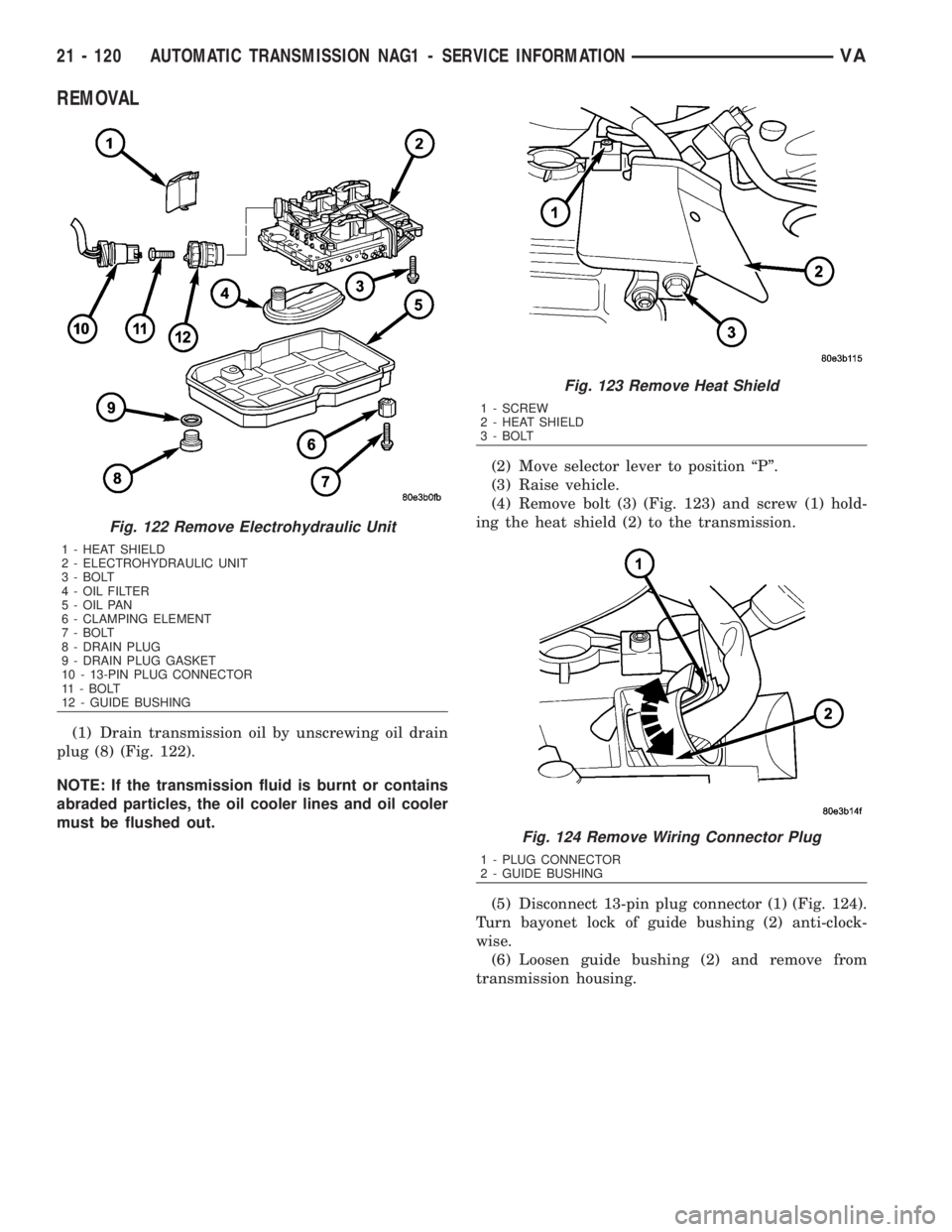
(1) Drain transmission oil by unscrewing oil drain
plug (8) (Fig. 122).
NOTE: If the transmission fluid is burnt or contains
abraded particles, the oil cooler lines and oil cooler
must be flushed out.(2) Move selector lever to position ªPº.
(3) Raise vehicle.
(4) Remove bolt (3) (Fig. 123) and screw (1) hold-
ing the heat shield (2) to the transmission.
(5) Disconnect 13-pin plug connector (1) (Fig. 124).
Turn bayonet lock of guide bushing (2) anti-clock-
wise.
(6) Loosen guide bushing (2) and remove from
transmission housing.
Fig. 122 Remove Electrohydraulic Unit
1 - HEAT SHIELD
2 - ELECTROHYDRAULIC UNIT
3 - BOLT
4 - OIL FILTER
5 - OIL PAN
6 - CLAMPING ELEMENT
7 - BOLT
8 - DRAIN PLUG
9 - DRAIN PLUG GASKET
10 - 13-PIN PLUG CONNECTOR
11 - BOLT
12 - GUIDE BUSHING
Fig. 123 Remove Heat Shield
1 - SCREW
2 - HEAT SHIELD
3 - BOLT
Fig. 124 Remove Wiring Connector Plug
1 - PLUG CONNECTOR
2 - GUIDE BUSHING
21 - 120 AUTOMATIC TRANSMISSION NAG1 - SERVICE INFORMATIONVA
Page 1864 of 2305
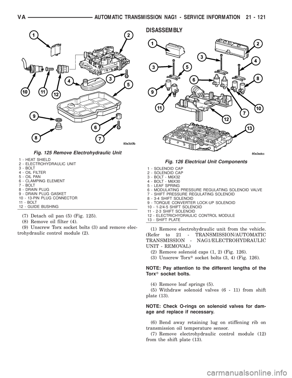
(7) Detach oil pan (5) (Fig. 125).
(8) Remove oil filter (4).
(9) Unscrew Torx socket bolts (3) and remove elec-
trohydraulic control module (2).
DISASSEMBLY
(1) Remove electrohydraulic unit from the vehicle.
(Refer to 21 - TRANSMISSION/AUTOMATIC
TRANSMISSION - NAG1/ELECTROHYDRAULIC
UNIT - REMOVAL)
(2) Remove solenoid caps (1, 2) (Fig. 126).
(3) Unscrew Torxtsocket bolts (3, 4) (Fig. 126).
NOTE: Pay attention to the different lengths of the
TorxTsocket bolts.
(4) Remove leaf springs (5).
(5) Withdraw solenoid valves (6 - 11) from shift
plate (13).
NOTE: Check O-rings on solenoid valves for dam-
age and replace if necessary.
(6) Bend away retaining lug on stiffening rib on
transmission oil temperature sensor.
(7) Remove electrohydraulic control module (12)
from the shift plate (13).
Fig. 125 Remove Electrohydraulic Unit
1 - HEAT SHIELD
2 - ELECTROHYDRAULIC UNIT
3 - BOLT
4 - OIL FILTER
5 - OIL PAN
6 - CLAMPING ELEMENT
7 - BOLT
8 - DRAIN PLUG
9 - DRAIN PLUG GASKET
10 - 13-PIN PLUG CONNECTOR
11 - BOLT
12 - GUIDE BUSHINGFig. 126 Electrical Unit Components
1 - SOLENOID CAP
2 - SOLENOID CAP
3 - BOLT - M6X32
4 - BOLT - M6X30
5 - LEAF SPRING
6 - MODULATING PRESSURE REGULATING SOLENOID VALVE
7 - SHIFT PRESSURE REGULATING SOLENOID
8 - 3-4 SHIFT SOLENOID
9 - TORQUE CONVERTER LOCK-UP SOLENOID
10 - 1-2/4-5 SHIFT SOLENOID
11 - 2-3 SHIFT SOLENOID
12 - ELECTRICHYDRAULIC CONTROL MODULE
13 - SHIFT PLATE
VAAUTOMATIC TRANSMISSION NAG1 - SERVICE INFORMATION 21 - 121
Page 1873 of 2305
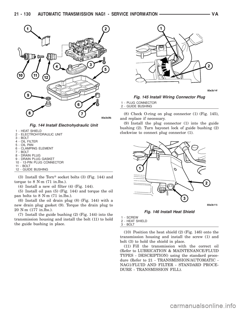
(3) Install the Torxtsocket bolts (3) (Fig. 144) and
torque to 8 N´m (71 in.lbs.).
(4) Install a new oil filter (4) (Fig. 144).
(5) Install oil pan (5) (Fig. 144) and torque the oil
pan bolts to 8 N´m (71 in.lbs.).
(6) Install the oil drain plug (8) (Fig. 144) with a
new drain plug gasket (9). Torque the drain plug to
20 N´m (177 in.lbs.).
(7) Install the guide bushing (2) (Fig. 144) into the
transmission housing and install the bolt (11) to hold
the guide bushing in place.(8) Check O-ring on plug connector (1) (Fig. 145),
and replace if necessary.
(9) Install the plug connector (1) into the guide
bushing (2). Turn bayonet lock of guide bushing (2)
clockwise to connect plug connector (1).
(10) Position the heat shield (2) (Fig. 146) onto the
transmission housing and install the screw (1) and
bolt (3) to hold the shield in place.
(11) Fill the transmission with the correct oil
(Refer to LUBRICATION & MAINTENANCE/FLUID
TYPES - DESCRIPTION) using the standard proce-
dure (Refer to 21 - TRANSMISSION/AUTOMATIC -
NAG1/FLUID AND FILTER - STANDARD PROCE-
DURE - TRANSMISSION FILL).
Fig. 144 Install Electrohydraulic Unit
1 - HEAT SHIELD
2 - ELECTROHYDRAULIC UNIT
3 - BOLT
4 - OIL FILTER
5 - OIL PAN
6 - CLAMPING ELEMENT
7 - BOLT
8 - DRAIN PLUG
9 - DRAIN PLUG GASKET
10 - 13-PIN PLUG CONNECTOR
11 - BOLT
12 - GUIDE BUSHING
Fig. 145 Install Wiring Connector Plug
1 - PLUG CONNECTOR
2 - GUIDE BUSHING
Fig. 146 Install Heat Shield
1 - SCREW
2 - HEAT SHIELD
3 - BOLT
21 - 130 AUTOMATIC TRANSMISSION NAG1 - SERVICE INFORMATIONVA
Page 1874 of 2305
FLUID AND FILTER
DESCRIPTION
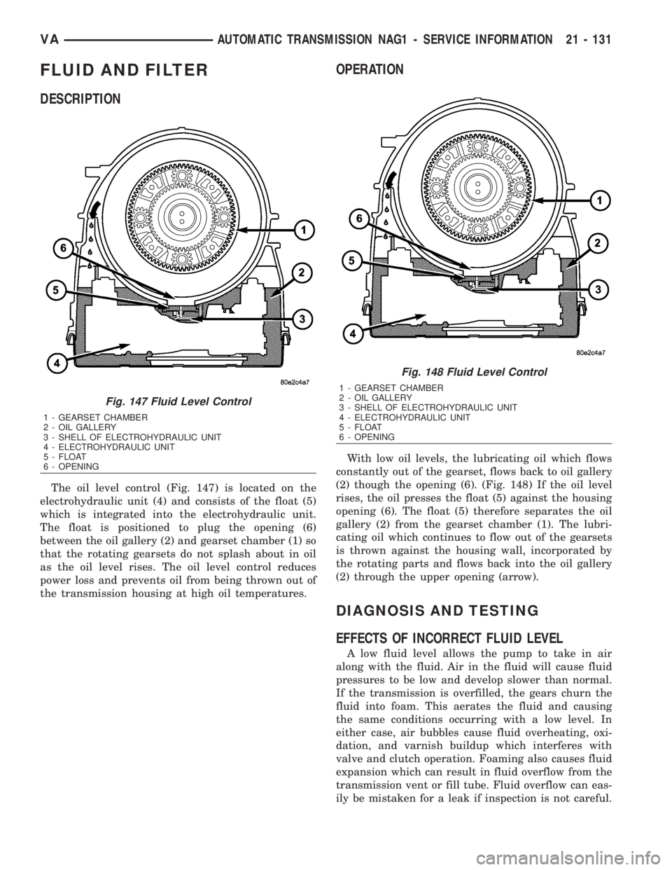
The oil level control (Fig. 147) is located on the
electrohydraulic unit (4) and consists of the float (5)
which is integrated into the electrohydraulic unit.
The float is positioned to plug the opening (6)
between the oil gallery (2) and gearset chamber (1) so
that the rotating gearsets do not splash about in oil
as the oil level rises. The oil level control reduces
power loss and prevents oil from being thrown out of
the transmission housing at high oil temperatures.
OPERATION
With low oil levels, the lubricating oil which flows
constantly out of the gearset, flows back to oil gallery
(2) though the opening (6). (Fig. 148) If the oil level
rises, the oil presses the float (5) against the housing
opening (6). The float (5) therefore separates the oil
gallery (2) from the gearset chamber (1). The lubri-
cating oil which continues to flow out of the gearsets
is thrown against the housing wall, incorporated by
the rotating parts and flows back into the oil gallery
(2) through the upper opening (arrow).
DIAGNOSIS AND TESTING
EFFECTS OF INCORRECT FLUID LEVEL
A low fluid level allows the pump to take in air
along with the fluid. Air in the fluid will cause fluid
pressures to be low and develop slower than normal.
If the transmission is overfilled, the gears churn the
fluid into foam. This aerates the fluid and causing
the same conditions occurring with a low level. In
either case, air bubbles cause fluid overheating, oxi-
dation, and varnish buildup which interferes with
valve and clutch operation. Foaming also causes fluid
expansion which can result in fluid overflow from the
transmission vent or fill tube. Fluid overflow can eas-
ily be mistaken for a leak if inspection is not careful.
Fig. 147 Fluid Level Control
1 - GEARSET CHAMBER
2 - OIL GALLERY
3 - SHELL OF ELECTROHYDRAULIC UNIT
4 - ELECTROHYDRAULIC UNIT
5 - FLOAT
6 - OPENING
Fig. 148 Fluid Level Control
1 - GEARSET CHAMBER
2 - OIL GALLERY
3 - SHELL OF ELECTROHYDRAULIC UNIT
4 - ELECTROHYDRAULIC UNIT
5 - FLOAT
6 - OPENING
VAAUTOMATIC TRANSMISSION NAG1 - SERVICE INFORMATION 21 - 131
Page 1877 of 2305
To avoid overfilling transmission after a fluid
change or overhaul, perform the following procedure:
(1) Verify that the vehicle is parked on a level sur-
face.
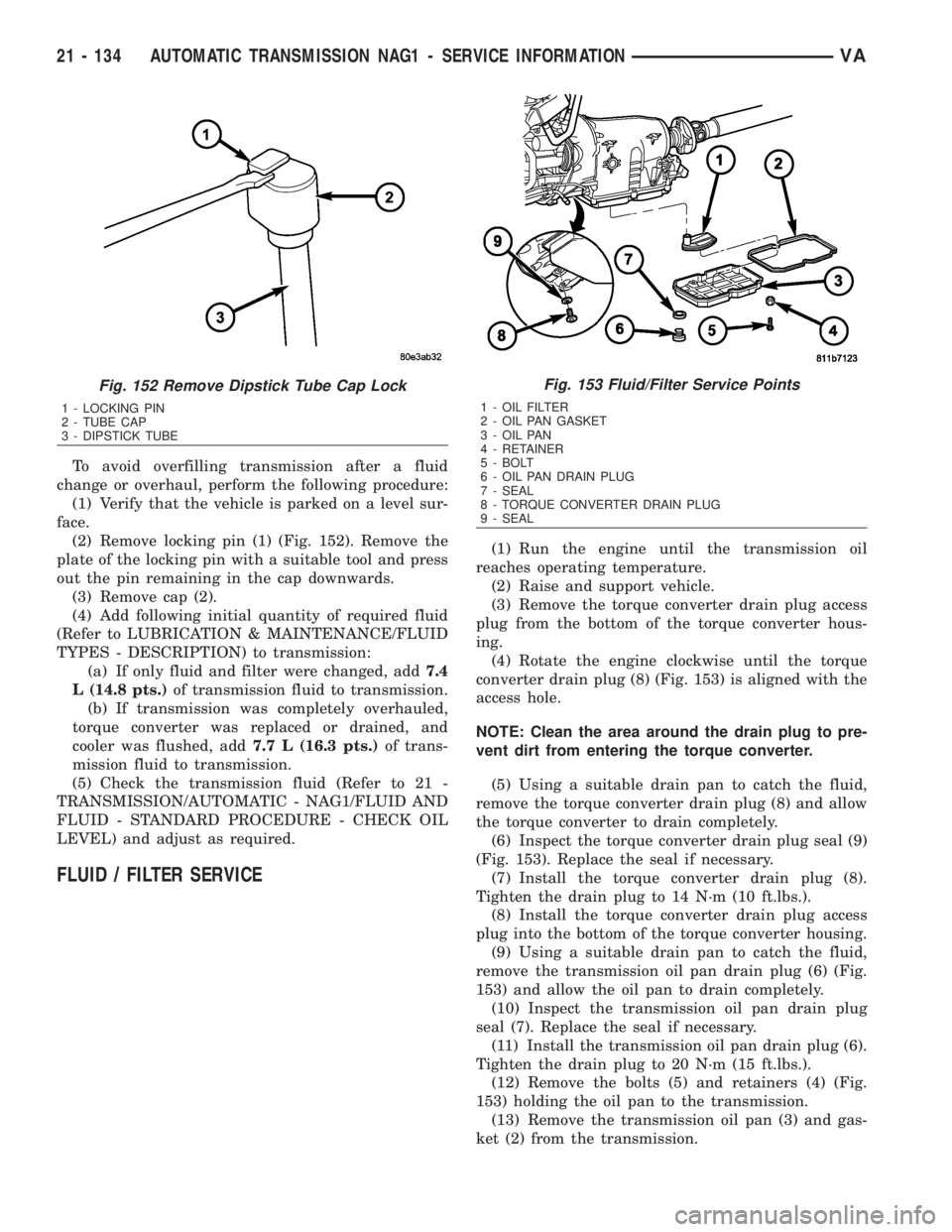
(2) Remove locking pin (1) (Fig. 152). Remove the
plate of the locking pin with a suitable tool and press
out the pin remaining in the cap downwards.
(3) Remove cap (2).
(4) Add following initial quantity of required fluid
(Refer to LUBRICATION & MAINTENANCE/FLUID
TYPES - DESCRIPTION) to transmission:
(a) If only fluid and filter were changed, add7.4
L (14.8 pts.)of transmission fluid to transmission.
(b) If transmission was completely overhauled,
torque converter was replaced or drained, and
cooler was flushed, add7.7 L (16.3 pts.)of trans-
mission fluid to transmission.
(5) Check the transmission fluid (Refer to 21 -
TRANSMISSION/AUTOMATIC - NAG1/FLUID AND
FLUID - STANDARD PROCEDURE - CHECK OIL
LEVEL) and adjust as required.
FLUID / FILTER SERVICE
(1) Run the engine until the transmission oil
reaches operating temperature.
(2) Raise and support vehicle.
(3) Remove the torque converter drain plug access
plug from the bottom of the torque converter hous-
ing.
(4) Rotate the engine clockwise until the torque
converter drain plug (8) (Fig. 153) is aligned with the
access hole.
NOTE: Clean the area around the drain plug to pre-
vent dirt from entering the torque converter.
(5) Using a suitable drain pan to catch the fluid,
remove the torque converter drain plug (8) and allow
the torque converter to drain completely.
(6) Inspect the torque converter drain plug seal (9)
(Fig. 153). Replace the seal if necessary.
(7) Install the torque converter drain plug (8).
Tighten the drain plug to 14 N´m (10 ft.lbs.).
(8) Install the torque converter drain plug access
plug into the bottom of the torque converter housing.
(9) Using a suitable drain pan to catch the fluid,
remove the transmission oil pan drain plug (6) (Fig.
153) and allow the oil pan to drain completely.
(10) Inspect the transmission oil pan drain plug
seal (7). Replace the seal if necessary.
(11) Install the transmission oil pan drain plug (6).
Tighten the drain plug to 20 N´m (15 ft.lbs.).
(12) Remove the bolts (5) and retainers (4) (Fig.
153) holding the oil pan to the transmission.
(13) Remove the transmission oil pan (3) and gas-
ket (2) from the transmission.
Fig. 152 Remove Dipstick Tube Cap Lock
1 - LOCKING PIN
2 - TUBE CAP
3 - DIPSTICK TUBE
Fig. 153 Fluid/Filter Service Points
1 - OIL FILTER
2 - OIL PAN GASKET
3 - OIL PAN
4 - RETAINER
5 - BOLT
6 - OIL PAN DRAIN PLUG
7 - SEAL
8 - TORQUE CONVERTER DRAIN PLUG
9 - SEAL
21 - 134 AUTOMATIC TRANSMISSION NAG1 - SERVICE INFORMATIONVA
Page 1878 of 2305
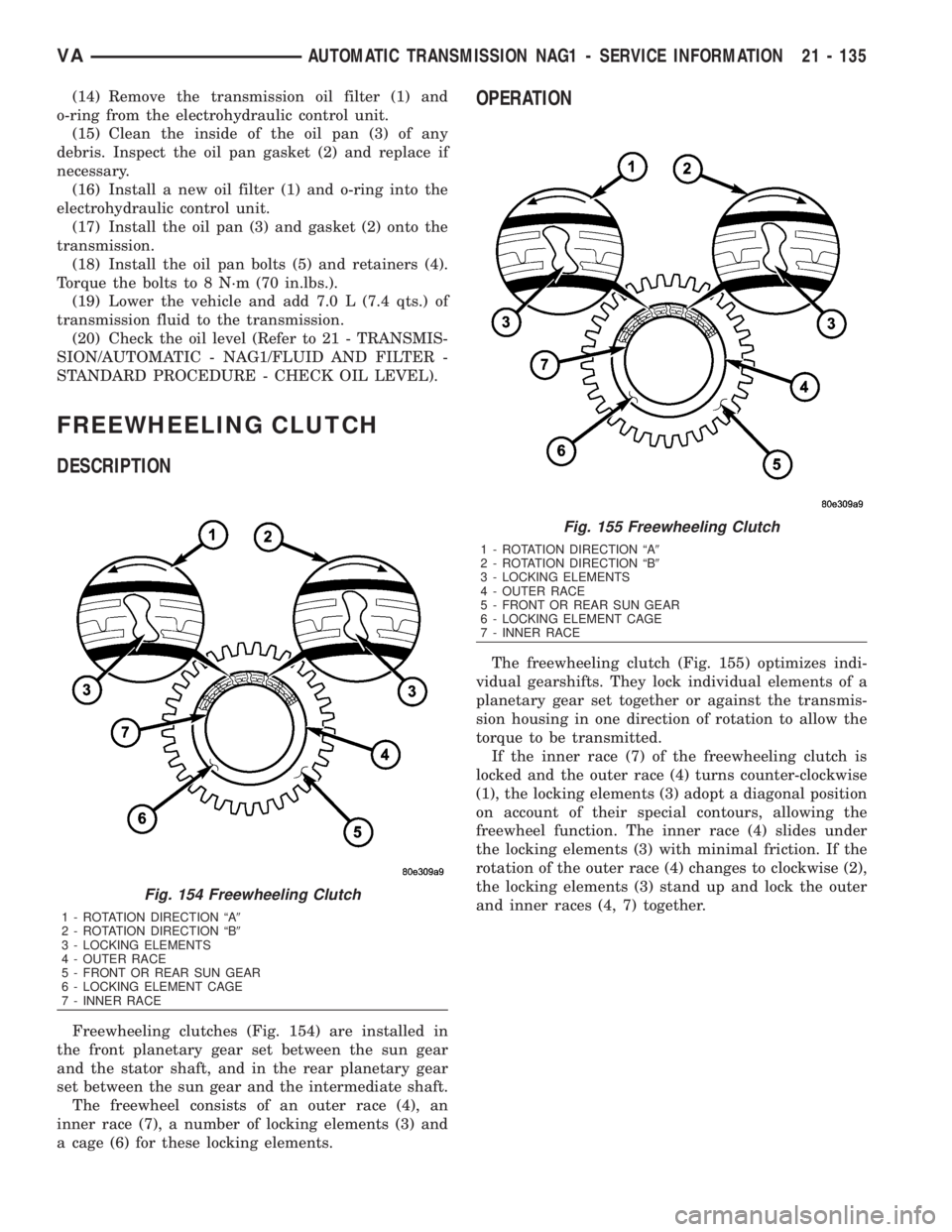
(14) Remove the transmission oil filter (1) and
o-ring from the electrohydraulic control unit.
(15) Clean the inside of the oil pan (3) of any
debris. Inspect the oil pan gasket (2) and replace if
necessary.
(16) Install a new oil filter (1) and o-ring into the
electrohydraulic control unit.
(17) Install the oil pan (3) and gasket (2) onto the
transmission.
(18) Install the oil pan bolts (5) and retainers (4).
Torque the bolts to 8 N´m (70 in.lbs.).
(19) Lower the vehicle and add 7.0 L (7.4 qts.) of
transmission fluid to the transmission.
(20) Check the oil level (Refer to 21 - TRANSMIS-
SION/AUTOMATIC - NAG1/FLUID AND FILTER -
STANDARD PROCEDURE - CHECK OIL LEVEL).
FREEWHEELING CLUTCH
DESCRIPTION
Freewheeling clutches (Fig. 154) are installed in
the front planetary gear set between the sun gear
and the stator shaft, and in the rear planetary gear
set between the sun gear and the intermediate shaft.
The freewheel consists of an outer race (4), an
inner race (7), a number of locking elements (3) and
a cage (6) for these locking elements.
OPERATION
The freewheeling clutch (Fig. 155) optimizes indi-
vidual gearshifts. They lock individual elements of a
planetary gear set together or against the transmis-
sion housing in one direction of rotation to allow the
torque to be transmitted.
If the inner race (7) of the freewheeling clutch is
locked and the outer race (4) turns counter-clockwise
(1), the locking elements (3) adopt a diagonal position
on account of their special contours, allowing the
freewheel function. The inner race (4) slides under
the locking elements (3) with minimal friction. If the
rotation of the outer race (4) changes to clockwise (2),
the locking elements (3) stand up and lock the outer
and inner races (4, 7) together.
Fig. 154 Freewheeling Clutch
1 - ROTATION DIRECTION ªA9
2 - ROTATION DIRECTION ªB9
3 - LOCKING ELEMENTS
4 - OUTER RACE
5 - FRONT OR REAR SUN GEAR
6 - LOCKING ELEMENT CAGE
7 - INNER RACE
Fig. 155 Freewheeling Clutch
1 - ROTATION DIRECTION ªA9
2 - ROTATION DIRECTION ªB9
3 - LOCKING ELEMENTS
4 - OUTER RACE
5 - FRONT OR REAR SUN GEAR
6 - LOCKING ELEMENT CAGE
7 - INNER RACE
VAAUTOMATIC TRANSMISSION NAG1 - SERVICE INFORMATION 21 - 135