2006 MERCEDES-BENZ SPRINTER oil filter
[x] Cancel search: oil filterPage 2079 of 2305
the rear A/C control module circuits and radio recep-
tion quality. The suppression filters for the rear
blower motors consist of capacitors and inductance
coils.
The rear blower motor suppression filters cannot
be repaired and, if faulty or damaged, they must be
replaced. Refer to the appropriate wiring information
for complete HVAC wiring diagrams.
REMOVAL
(1) Disconnect and isolate the negative battery
cable.
(2) Remove the cover from the rear A/C evaporator
housing (Refer to 24 - HEATING & AIR CONDI-
TIONING/DISTRIBUTION - REAR/A/C EVAPORA-
TOR COVER-REAR - REMOVAL).
(3) Disconnect the two wire harness connectors
from the rear blower motor suppression filter being
serviced (Fig. 22).
(4) Remove the screw that secures the each rear
blower motor suppression filter to the rear A/C evap-
orator housing and remove the suppression filters as
required.
24 - 42 CONTROLS - REARVA
Page 2081 of 2305
OPERATION
The rear condenser fan suppression filter provides
protection against transient interference signals or
similar interference to the electronic rear condenser
fan circuits which can effect the performance of the
rear A/C control module circuits and radio reception
quality. The suppression filter for the rear condenser
fan consist of capacitors and inductance coils.
The rear condenser fan suppression filter cannot be
repaired and, if faulty or damaged, it must be
replaced. Refer to the appropriate wiring information
for complete HVAC wiring diagrams.
REMOVAL
(1) Disconnect and isolate the negative battery
cable.
(2) Remove the cover from the rear A/C condenser
housing (Refer to 24 - HEATING & AIR CONDI-
TIONING/DISTRIBUTION - REAR/A/C CON-
DENSER COVER-REAR - REMOVAL).
(3) Disconnect the two wire harness connectors
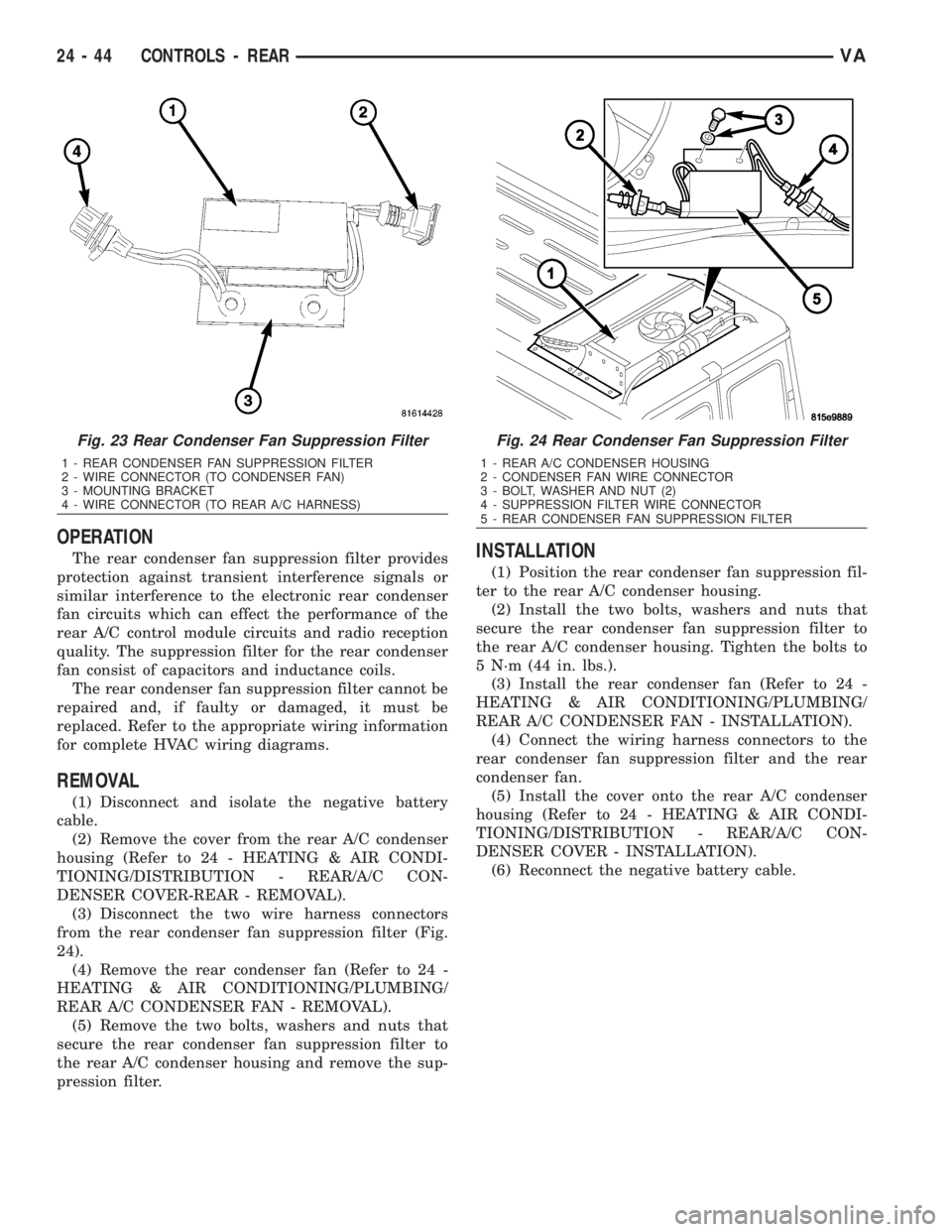
from the rear condenser fan suppression filter (Fig.
24).
(4) Remove the rear condenser fan (Refer to 24 -
HEATING & AIR CONDITIONING/PLUMBING/
REAR A/C CONDENSER FAN - REMOVAL).
(5) Remove the two bolts, washers and nuts that
secure the rear condenser fan suppression filter to
the rear A/C condenser housing and remove the sup-
pression filter.
INSTALLATION
(1) Position the rear condenser fan suppression fil-
ter to the rear A/C condenser housing.
(2) Install the two bolts, washers and nuts that
secure the rear condenser fan suppression filter to
the rear A/C condenser housing. Tighten the bolts to
5 N´m (44 in. lbs.).
(3) Install the rear condenser fan (Refer to 24 -
HEATING & AIR CONDITIONING/PLUMBING/
REAR A/C CONDENSER FAN - INSTALLATION).
(4) Connect the wiring harness connectors to the
rear condenser fan suppression filter and the rear
condenser fan.
(5) Install the cover onto the rear A/C condenser
housing (Refer to 24 - HEATING & AIR CONDI-
TIONING/DISTRIBUTION - REAR/A/C CON-
DENSER COVER - INSTALLATION).
(6) Reconnect the negative battery cable.
Fig. 23 Rear Condenser Fan Suppression Filter
1 - REAR CONDENSER FAN SUPPRESSION FILTER
2 - WIRE CONNECTOR (TO CONDENSER FAN)
3 - MOUNTING BRACKET
4 - WIRE CONNECTOR (TO REAR A/C HARNESS)
Fig. 24 Rear Condenser Fan Suppression Filter
1 - REAR A/C CONDENSER HOUSING
2 - CONDENSER FAN WIRE CONNECTOR
3 - BOLT, WASHER AND NUT (2)
4 - SUPPRESSION FILTER WIRE CONNECTOR
5 - REAR CONDENSER FAN SUPPRESSION FILTER
24 - 44 CONTROLS - REARVA
Page 2091 of 2305
INSTALLATION
NOTE: Be certain to add refrigerant oil if the rear
A/C condenser is being replaced. The refrigerant oil
must be drained from the old condenser and mea-
sured to determine the amount of refrigerant oil to
add to the new condenser. Use only refrigerant oil
of the type recommended for the rear A/C compres-
sor in the vehicle.
(1) If the rear A/C condenser is being replaced,
install the correct amount and type of refrigerant oil
into the new rear A/C condenser. Drain the old con-
denser and measure the refrigerant oil. Fill the new
condenser with the same amount of new refrigerant
oil that was drained out of the old condenser.
(2) Install new body sealant and any removed
shims onto the top of the roof panel.
(3) With help from an assistant, position the rear
A/C condenser housing onto the top of the roof panel.
(4) Install the eight nuts and washers that secure
the rear A/C condenser housing to the roof panel.
Tighten the nuts to 25 N´m (18 ft. lbs.).
(5) Remove the tape or plugs from the rear liquid
line fitting and rear refrigerant reservoir port.
(6) Lubricate a new O-ring seal with clean refrig-
erant oil and install it onto the rear liquid line fit-
ting. Use only the specified O-ring seal as it is madeof a special material for the R-134a system. Use only
refrigerant oil of the type recommended for the rear
A/C compressor in the vehicle.
(7) Connect the rear liquid line to the rear refrig-
erant reservoir outlet. Tighten the liquid line nut to
35 N´m (26 ft. lbs.).
(8) Remove the tape or plugs from the rear dis-
charge line fitting and rear condenser port.
(9) Lubricate a new O-ring seal with clean refrig-
erant oil and install it onto the rear discharge line
fitting. Use only the specified O-ring seal as it is
made of a special material for the R-134a system.
Use only refrigerant oil of the type recommended for
the rear A/C compressor in the vehicle.
(10) Connect the rear discharge line to the rear
A/C condenser. Tighten the discharge line nut to 35
N´m (26 ft. lbs.).
(11) Install the bracket and screw that secures the
rear discharge line to the right side of the rear con-
denser housing. Tighten the screw securely.
(12) Connect the rear A/C wire harness to the rear
blower motor suppression filter and to the rear A/C
high pressure switch.
(13) Install new retaining straps to secure the rear
A/C wire harness to the rear liquid line.
(14) Install a new rear receiver/drier (Refer to 24 -
HEATING & AIR CONDITIONING/PLUMBING/
REAR RECEIVER/DRIER - INSTALLATION).
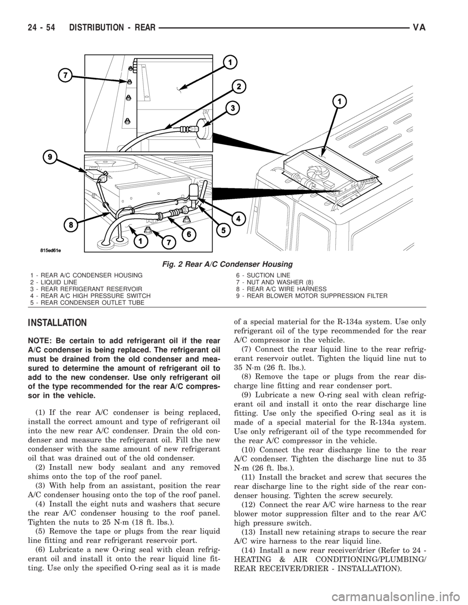
Fig. 2 Rear A/C Condenser Housing
1 - REAR A/C CONDENSER HOUSING
2 - LIQUID LINE
3 - REAR REFRIGERANT RESERVOIR
4 - REAR A/C HIGH PRESSURE SWITCH
5 - REAR CONDENSER OUTLET TUBE6 - SUCTION LINE
7 - NUT AND WASHER (8)
8 - REAR A/C WIRE HARNESS
9 - REAR BLOWER MOTOR SUPPRESSION FILTER
24 - 54 DISTRIBUTION - REARVA
Page 2095 of 2305
(10) Lubricate a new O-ring seal with clean refrig-
erant oil and install it onto the rear suction line fit-
ting. Use only the specified O-ring seal as it is made
of a special material for the R-134a system. Use only
refrigerant oil of the type recommended for the rear
A/C compressor in the vehicle.
(11) Connect the rear suction line to the rear evap-
orator outlet tube. Tighten the suction line nut to 35
N´m (26 ft. lbs.).
(12) Install new insulating tape around the rear
evaporator connections.
(13) Install the positive wire lead onto the rear
A/C system terminal block and install the retaining
nut. Tighten the nut securely.
(14) Reposition the rear dome lamp harness and
install the retaining straps that secure the harness
to the rear A/C evaporator housing.
(15) Connect the rear A/C wire harness connector
to the rear body wire harness.
(16) Route the rear A/C wire harness up through
the roof panel and install the grommet.
(17) Connect the rear A/C wire harness to the rear
condenser fan suppression filter and the rear A/C
high pressure switch and install the retaining straps
that secure the wire harness to the rear liquid line.
(18) Reconnect the negative battery cable.
(19) Evacuate the rear refrigerant system (Refer to
24 - HEATING & AIR CONDITIONING/PLUMBING
- STANDARD PROCEDURE - REFRIGERANT SYS-
TEM EVACUATE).
(20) Charge the rear refrigerant system (Refer to
24 - HEATING & AIR CONDITIONING/PLUMBING
- STANDARD PROCEDURE - REFRIGERANT SYS-
TEM CHARGE).
(21) Install the cover onto the rear A/C evaporator
housing (Refer to 24 - HEATING & AIR CONDI-
TIONING/DISTRIBUTION - REAR/A/C EVAPORA-
TOR COVER-REAR - INSTALLATION).
(22) Install the cover onto the rear A/C condenser
housing (Refer to 24 - HEATING & AIR CONDI-
TIONING/DISTRIBUTION - REAR/A/C CON-
DENSER COVER - INSTALLATION).
AIR FILTER
REMOVAL
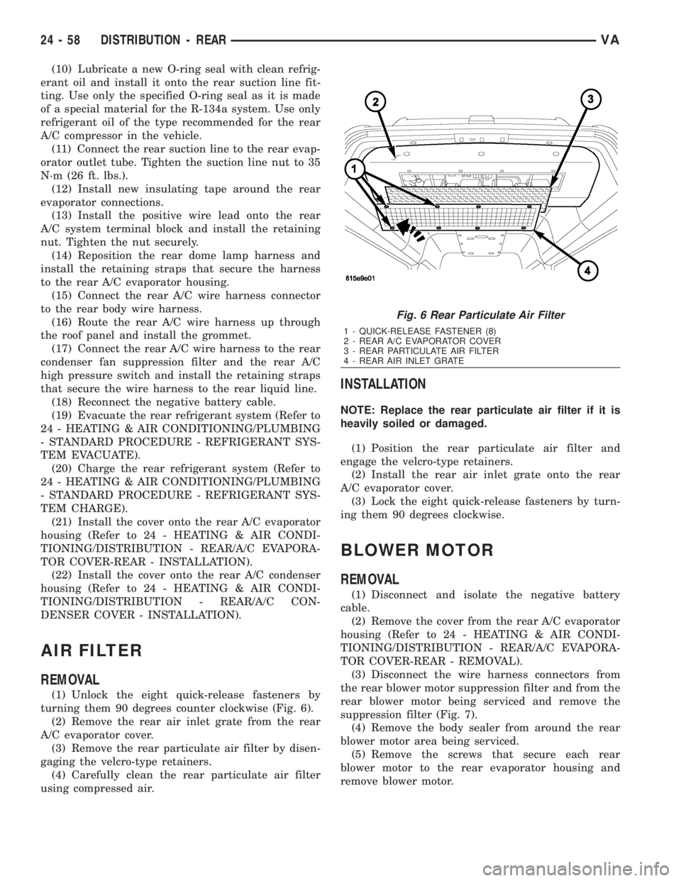
(1) Unlock the eight quick-release fasteners by
turning them 90 degrees counter clockwise (Fig. 6).
(2) Remove the rear air inlet grate from the rear
A/C evaporator cover.
(3) Remove the rear particulate air filter by disen-
gaging the velcro-type retainers.
(4) Carefully clean the rear particulate air filter
using compressed air.
INSTALLATION
NOTE: Replace the rear particulate air filter if it is
heavily soiled or damaged.
(1) Position the rear particulate air filter and
engage the velcro-type retainers.
(2) Install the rear air inlet grate onto the rear
A/C evaporator cover.
(3) Lock the eight quick-release fasteners by turn-
ing them 90 degrees clockwise.
BLOWER MOTOR
REMOVAL
(1) Disconnect and isolate the negative battery
cable.
(2) Remove the cover from the rear A/C evaporator
housing (Refer to 24 - HEATING & AIR CONDI-
TIONING/DISTRIBUTION - REAR/A/C EVAPORA-
TOR COVER-REAR - REMOVAL).
(3) Disconnect the wire harness connectors from
the rear blower motor suppression filter and from the
rear blower motor being serviced and remove the
suppression filter (Fig. 7).
(4) Remove the body sealer from around the rear
blower motor area being serviced.
(5) Remove the screws that secure each rear
blower motor to the rear evaporator housing and
remove blower motor.
Fig. 6 Rear Particulate Air Filter
1 - QUICK-RELEASE FASTENER (8)
2 - REAR A/C EVAPORATOR COVER
3 - REAR PARTICULATE AIR FILTER
4 - REAR AIR INLET GRATE
24 - 58 DISTRIBUTION - REARVA
Page 2116 of 2305
INSTALLATION
NOTE: The A/C liquid line is serviced in two sec-
tions. The front section connects between the A/C
condenser and the receiver/drier and includes the
high side service port and the A/C pressure trans-
ducer on the fitting for the receiver/drier. The rear
section connects between the receiver/drier and the
A/C expansion valve.
FRONT SECTION
(1) Position the front section of the A/C liquid line
into the engine compartment.
(2) Remove the tape or plugs from the liquid line
fitting and the receiver/drier inlet port.
(3) Lubricate a new rubber O-ring seal with clean
refrigerant oil and install it on the liquid line fitting.
(4) Connect the front section of the liquid line to
the receiver/drier.
(5) Install the bolt that secures the liquid line fit-
ting to the receiver/drier. Tighten the bolt to 7 N´m
(62 in. lbs.).
(6) Position the front section of the liquid line into
the routing clip and install the routing clip onto the
body stud on the left frame rail.
(7) Install the routing clip retaining nut. Tighten
the nut to 5 N´m (45 in. lbs.).
(8) Remove the tape or plugs from the condenser
outlet port and the liquid line fitting.
(9) Lubricate a new O-ring seal with clean refrig-
erant oil and install it on the liquid line fitting.
(10) Connect the liquid line fitting to the con-
denser outlet port on the right side of the condenser.
(11) Install the nut that secures the liquid line fit-
ting to the condenser. Tighten the nut to 17 N´m (12
ft. lbs.).
(12) Reinstall the A/C pressure transducer (Refer
to 24 - HEATING & AIR CONDITIONING/CON-
TROLS/A/C PRESSURE TRANSDUCER - INSTAL-
LATION).
(13) Install the grille (Refer to 23 - BODY/EXTE-
RIOR/GRILLE - INSTALLATION).
(14) Reconnect the battery negative cable.
(15) Evacuate the refrigerant system (Refer to 24 -
HEATING & AIR CONDITIONING/PLUMBING/RE-
FRIGERANT - STANDARD PROCEDURE -
REFRIGERANT SYSTEM EVACUATE).
(16) Charge the refrigerant system (Refer to 24 -
HEATING & AIR CONDITIONING/PLUMBING/RE-
FRIGERANT - STANDARD PROCEDURE -
REFRIGERANT SYSTEM CHARGE).
REAR SECTION
(1) Position the rear section of the A/C liquid line
into the engine compartment.(2) Remove the tape or plugs from the liquid and
suction line fittings, the receiver/drier outlet port and
both expansion valve ports.
(3) Lubricate new rubber O-ring seals with clean
refrigerant oil and install them onto the suction and
liquid line fittings for the expansion valve.
(4) Connect the liquid line and suction line fittings
to the A/C expansion valve.
(5) Install the nut that secures the suction line
and liquid line fittings to the stud on the A/C expan-
sion valve. Tighten the nut to 10 N´m (89 in. lbs.).
(6) Lubricate new rubber O-ring seal with clean
refrigerant oil and install it on the liquid line fitting.
(7) Connect the liquid line fitting to the receiver/
drier outlet port.
(8) Install the bolt that secures the liquid line fit-
ting to the receiver/drier. Tighten the bolt to 7 N´m
(62 in. lbs.).
(9) Install the routing clip retainer to the rear sec-
tion of the liquid line.
(10) Install the grille (Refer to 23 - BODY/EXTE-
RIOR/GRILLE - INSTALLATION).
(11) Reconnect the negative battery cable.
(12) Evacuate the refrigerant system (Refer to 24 -
HEATING & AIR CONDITIONING/PLUMBING/RE-
FRIGERANT - STANDARD PROCEDURE -
REFRIGERANT SYSTEM EVACUATE).
(13) Charge the refrigerant system (Refer to 24 -
HEATING & AIR CONDITIONING/PLUMBING/RE-
FRIGERANT - STANDARD PROCEDURE -
REFRIGERANT SYSTEM CHARGE).
RECEIVER / DRIER
DESCRIPTION
The receiver/drier is mounted in a bracket secured
to the left front strut tower in the engine compart-
ment. The receiver/drier is connected between the
front and rear sections of the A/C liquid line between
the condenser outlet and the evaporator inlet.
The receiver/drier cannot be repaired. If the receiv-
er/drier is faulty or damaged, or if the refrigerant
system has been contaminated or left open to the
atmosphere for an indeterminable period or if the
compressor has failed, it must be replaced.
OPERATION
The receiver/drier performs a filtering action to
prevent foreign material in the refrigerant from con-
taminating the A/C expansion valve. Refrigerant
enters the receiver/drier as a high-pressure, low tem-
perature liquid. Desiccant inside the receiver/drier
absorbs any moisture which may have entered and
become trapped within the refrigerant system. In
addition, during periods of high demand operation of
the A/C system, the receiver/drier acts as a reservoir
to store surplus refrigerant.
VAPLUMBING 24 - 79
Page 2130 of 2305
INSTALLATION
CONDENSER TO RECEIVER / DRIER
(1) Remove the tape or plugs from the rear liquid
line fittings and receiver/drier and condenser ports.
(2) Lubricate new O-ring seals with clean refriger-
ant oil and install them onto the rear liquid line fit-
tings. Use only the specified O-ring seals as they are
made of a special material for the R-134a system.
Use only refrigerant oil of the type recommended for
the rear A/C compressor in the vehicle.
(3) Connect the rear liquid line to the rear receiv-
er/drier. Tighten the nut to 35 N´m (26 ft. lbs.).
(4) Connect the rear liquid line to the rear A/C
condenser. Tighten the nut to 35 N´m (26 ft. lbs.).
(5) Install the retaining straps that secure the rear
A/C wire harness to the rear liquid line.
(6) Reconnect the negative battery cable.
(7) Evacuate the rear refrigerant system (Refer to
24 - HEATING & AIR CONDITIONING/PLUMBING
- STANDARD PROCEDURE - REFRIGERANT SYS-
TEM EVACUATE).
(8) Charge the rear refrigerant system (Refer to 24
- HEATING & AIR CONDITIONING/PLUMBING -
STANDARD PROCEDURE - REFRIGERANT SYS-
TEM CHARGE).
(9) Install the rear air filter (Refer to 24 - HEAT-
ING & AIR CONDITIONING/DISTRIBUTION -
REAR/AIR FILTER - INSTALLATION).(10) Install the cover onto the rear A/C condenser
housing (Refer to 24 - HEATING & AIR CONDI-
TIONING/DISTRIBUTION - REAR/A/C CON-
DENSER COVER - INSTALLATION).
RESERVOIR TO EXPANSION VALVE
(1) Remove the tape or plugs from the rear liquid
line fittings and the reservoir and expansion valve
ports.
(2) Lubricate new O-ring seals with clean refriger-
ant oil and install them onto the rear liquid line fit-
tings. Use only the specified O-ring seals as they are
made of a special material for the R-134a system.
Use only refrigerant oil of the type recommended for
the rear A/C compressor in the vehicle.
(3) Connect the rear liquid line to the rear A/C
expansion valve. Tighten the nut to 35 N´m (26 ft.
lbs.).
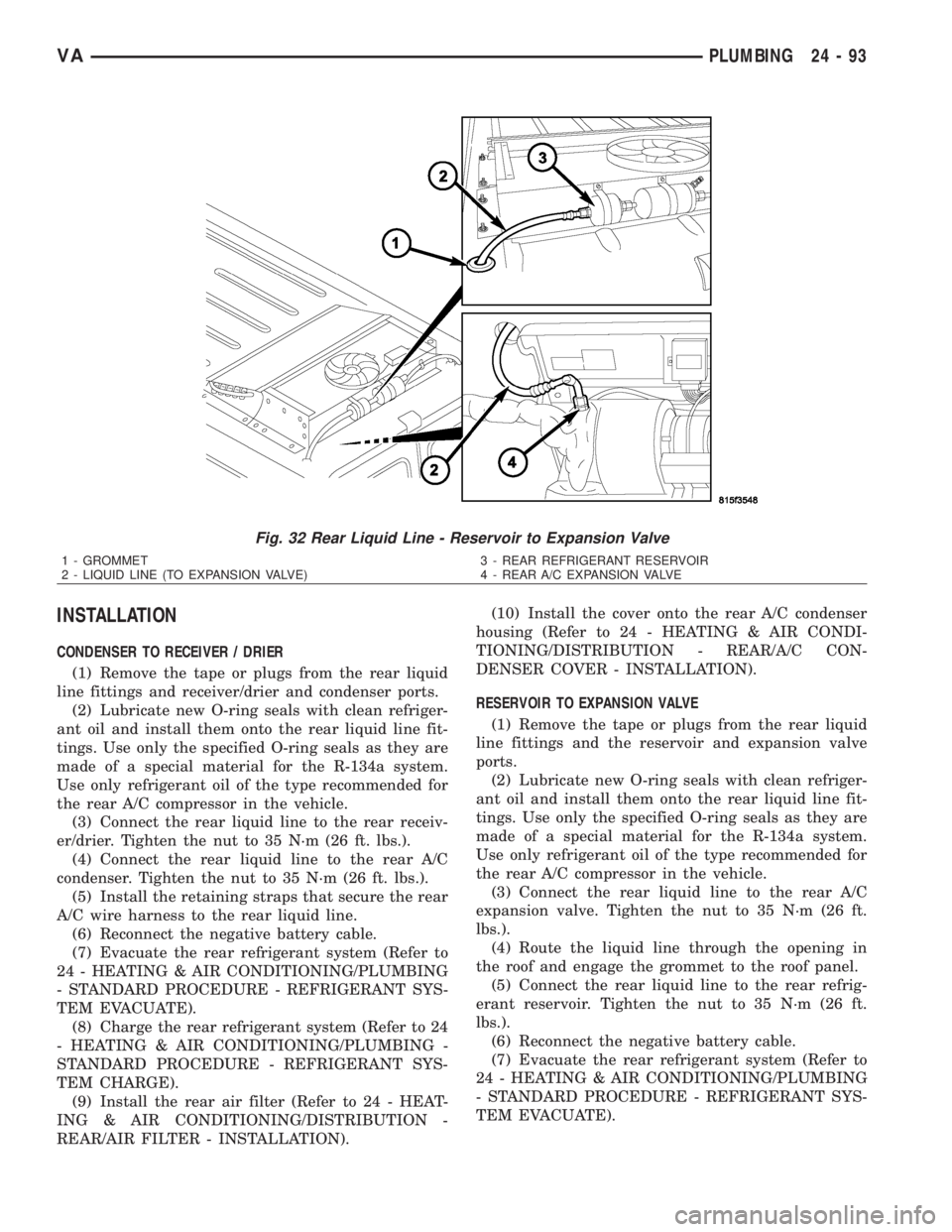
(4) Route the liquid line through the opening in
the roof and engage the grommet to the roof panel.
(5) Connect the rear liquid line to the rear refrig-
erant reservoir. Tighten the nut to 35 N´m (26 ft.
lbs.).
(6) Reconnect the negative battery cable.
(7) Evacuate the rear refrigerant system (Refer to
24 - HEATING & AIR CONDITIONING/PLUMBING
- STANDARD PROCEDURE - REFRIGERANT SYS-
TEM EVACUATE).
Fig. 32 Rear Liquid Line - Reservoir to Expansion Valve
1 - GROMMET
2 - LIQUID LINE (TO EXPANSION VALVE)3 - REAR REFRIGERANT RESERVOIR
4 - REAR A/C EXPANSION VALVE
VAPLUMBING 24 - 93
Page 2131 of 2305
(8) Charge the rear refrigerant system (Refer to 24
- HEATING & AIR CONDITIONING/PLUMBING -
STANDARD PROCEDURE - REFRIGERANT SYS-
TEM CHARGE).
(9) Install the cover onto the rear A/C evaporator
housing (Refer to 24 - HEATING & AIR CONDI-
TIONING/DISTRIBUTION - REAR/A/C EVAPORA-
TOR COVER-REAR - INSTALLATION).
(10) Install the cover onto the rear A/C condenser
housing (Refer to 24 - HEATING & AIR CONDI-
TIONING/DISTRIBUTION - REAR/A/C CON-
DENSER COVER - INSTALLATION).
REAR RECEIVER / DRIER
REMOVAL
WARNING: Refer to the applicable warnings and
cautions for this system before performing the fol-
lowing operation (Refer to 24 - HEATING & AIR
CONDITIONING/PLUMBING - WARNINGS) and (Refer
to 24 - HEATING & AIR CONDITIONING/PLUMBING -
CAUTIONS). Failure to follow the warnings and cau-
tions could result in possible personal injury or
death.
(1) Disconnect and isolate the negative battery
cable.
(2) Remove the air filter from the rear A/C evapo-
rator housing (Refer to 24 - HEATING & AIR CON-
DITIONING/DISTRIBUTION - REAR/AIR FILTER -
REMOVAL).
(3) Recover the refrigerant from the rear refriger-
ant system (Refer to 24 - HEATING & AIR CONDI-
TIONING/PLUMBING - STANDARD PROCEDURE -
REFRIGERANT RECOVERY).
(4) Remove the cover from the rear A/C condenser
housing (Refer to 24 - HEATING & AIR CONDI-
TIONING/DISTRIBUTION - REAR/A/C CON-
DENSER COVER - REMOVAL).
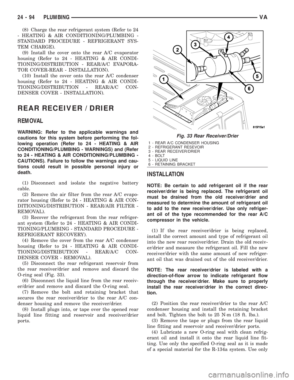
(5) Disconnect the rear refrigerant reservoir from
the rear receiver/drier and remove and discard the
O-ring seal (Fig. 33).
(6) Disconnect the liquid line from the rear receiv-
er/drier and remove and discard the O-ring seal.
(7) Remove the bolt and retaining bracket that
secures the rear receiver/drier to the rear A/C con-
denser housing and remove the receiver/drier.
(8) Install plugs into, or tape over the opened rear
liquid line fitting and reservoir and receiver/drier
ports.
INSTALLATION
NOTE: Be certain to add refrigerant oil if the rear
receiver/drier is being replaced. The refrigerant oil
must be drained from the old receiver/drier and
measured to determine the amount of refrigerant oil
to add to the new receiver/drier. Use only refriger-
ant oil of the type recommended for the rear A/C
compressor in the vehicle.
(1) If the rear receiver/drier is being replaced,
install the correct amount and type of refrigerant oil
into the new rear receiver/drier. Drain the old receiv-
er/drier and measure the refrigerant oil. Fill the new
receiver/drier with the same amount of new refriger-
ant oil that was drained out of the old receiver/drier.
NOTE: The rear receiver/drier is labeled with a
direction-of-flow arrow to indicate refrigerant flow
through the receiver/drier. Make sure to properly
install the rear receiver/drier in the correct direc-
tion.
(2) Position the rear receiver/drier to the rear A/C
condenser housing and install the retaining bracket
and bolt. Tighten the bolt to 25 N´m (18 ft. lbs.).
(3) Remove the tape or plugs from the rear liquid
line fitting and reservoir and receiver/drier ports.
(4) Lubricate a new O-ring seal with clean refrig-
erant oil and install it onto the rear liquid line fit-
ting. Use only the specified O-ring seal as it is made
of a special material for the R-134a system. Use only
Fig. 33 Rear Receiver/Drier
1 - REAR A/C CONDENSER HOUSING
2 - REFRIGERANT RESEVOIR
3 - REAR RECEIVER/DRIER
4 - BOLT
5 - LIQUID LINE
6 - RETAINING BRACKET
24 - 94 PLUMBINGVA
Page 2132 of 2305
refrigerant oil of the type recommended for the rear
A/C compressor in the vehicle.
(5) Connect the rear liquid line to the rear receiv-
er/drier. Tighten the nut to 35 N´m (26 ft. lbs.).
(6) Lubricate a new O-ring seal with clean refrig-
erant oil and install it onto the receiver/drier outlet
fitting. Use only the specified O-ring seal as it is
made of a special material for the R-134a system.
Use only refrigerant oil of the type recommended for
the rear A/C compressor in the vehicle.
(7) Connect the rear refrigerant reservoir to the
rear receiver/drier. Tighten the nut to 35 N´m (26 ft.
lbs.).
(8) Reconnect the negative battery cable.
(9) Evacuate the rear refrigerant system (Refer to
24 - HEATING & AIR CONDITIONING/PLUMBING
- STANDARD PROCEDURE - REFRIGERANT SYS-
TEM EVACUATE).
(10) Charge the rear refrigerant system (Refer to
24 - HEATING & AIR CONDITIONING/PLUMBING
- STANDARD PROCEDURE - REFRIGERANT SYS-
TEM CHARGE).
(11) Install the rear air filter (Refer to 24 - HEAT-
ING & AIR CONDITIONING/DISTRIBUTION -
REAR/AIR FILTER - INSTALLATION).
(12) Install the cover onto the rear A/C condenser
housing (Refer to 24 - HEATING & AIR CONDI-
TIONING/DISTRIBUTION - REAR/A/C CON-
DENSER COVER - INSTALLATION).
REAR REFRIGERANT RESER-
VOIR
REMOVAL
WARNING: Refer to the applicable warnings and
cautions for this system before performing the fol-
lowing operation (Refer to 24 - HEATING & AIR
CONDITIONING/PLUMBING - WARNINGS) and (Refer
to 24 - HEATING & AIR CONDITIONING/PLUMBING -
CAUTIONS). Failure to follow the warnings and cau-
tions could result in possible personal injury or
death.
(1) Disconnect and isolate the negative battery
cable.
(2) Remove the air filter from the rear A/C evapo-
rator housing (Refer to 24 - HEATING & AIR CON-
DITIONING/DISTRIBUTION - REAR/AIR FILTER -
REMOVAL).
(3) Recover the refrigerant from the rear refriger-
ant system (Refer to 24 - HEATING & AIR CONDI-
TIONING/PLUMBING - STANDARD PROCEDURE -
REFRIGERANT RECOVERY).
(4) Remove the cover from the rear A/C condenser
housing (Refer to 24 - HEATING & AIR CONDI-TIONING/DISTRIBUTION - REAR/A/C CON-
DENSER COVER - REMOVAL).
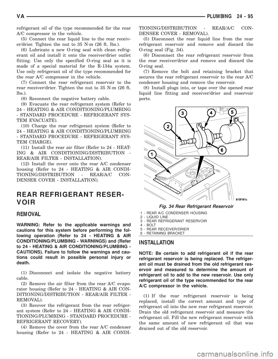
(5) Disconnect the rear liquid line from the rear
refrigerant reservoir and remove and discard the
O-ring seal (Fig. 34).
(6) Disconnect the rear refrigerant reservoir from
the rear receiver/drier and remove and discard the
O-ring seal.
(7) Remove the bolt and retaining bracket that
secures the rear refrigerant reservoir to the rear A/C
condenser housing and remove the reservoir.
(8) Install plugs into, or tape over the opened rear
liquid line fitting and receiver/drier and reservoir
ports.
INSTALLATION
NOTE: Be certain to add refrigerant oil if the rear
refrigerant reservoir is being replaced. The refriger-
ant oil must be drained from the old refrigerant res-
ervoir and measured to determine the amount of
refrigerant oil to add to the new reservoir. Use only
refrigerant oil of the type recommended for the rear
A/C compressor in the vehicle.
(1) If the rear refrigerant reservoir is being
replaced, install the correct amount and type of
refrigerant oil into the new rear refrigerant reservoir.
Drain the old refrigerant reservoir and measure the
refrigerant oil. Fill the new refrigerant reservoir with
the same amount of new refrigerant oil that was
drained out of the old reservoir.
Fig. 34 Rear Refrigerant Reservoir
1 - REAR A/C CONDENSER HOUSING
2 - LIQUID LINE
3 - REAR REFRIGERANT RESERVOIR
4 - BOLT
5 - REAR RECEIVER/DRIER
6 - RETAINING BRACKET
VAPLUMBING 24 - 95