2006 MERCEDES-BENZ SPRINTER oil filter
[x] Cancel search: oil filterPage 2046 of 2305
OPERATION
The compressor clutch components provide the
means to engage and disengage the compressor from
the engine serpentine accessory drive belt. When the
clutch coil is energized, it magnetically draws the
clutch into contact with the pulley and drives the
compressor shaft. When the coil is not energized, the
pulley freewheels on the clutch hub bearing, which is
part of the pulley.
The compressor clutch engagement is controlled by
several components:
²A/C switch on the A/C-heater control panel
²Evaporator temperature sensor
²A/C pressure transducer
²Air temperature sensor
²CAN bus messages
The compressor clutch is de-energized under any of
the following conditions:
²Blocked compressor (thermal fuse in the pulley)
²Low pressure in the system
²Low evaporator temperature
²Hard acceleration (WOT)
²High coolant temperatures
STANDARD PROCEDURE
A / C COMPRESSOR CLUTCH AIR GAP
If a new clutch plate and/or clutch pulley are being
used, the air gap between the clutch plate and clutch
pulley must be checked using the following proce-
dure:
(1) Using feeler gauges, measure the air gap
between the clutch plate and the clutch pulley fric-
tion surfaces.
(2) If the air gap is not between specifications
(Refer to 24 - HEATING & AIR CONDITIONING -
SPECIFICATIONS), add or subtract shims until the
desired air gap is obtained.
NOTE: The shims may compress after tightening
the compressor shaft bolt. Check the air gap in four
or more places on the clutch plate to verify that the
air gap is still correct. Spin the clutch pulley before
making the final air gap check.
A / C COMPRESSOR CLUTCH BREAK - IN
After a new compressor clutch has been installed,
cycle the compressor clutch approximately twenty
times (five seconds on, then five seconds off). During
this procedure, set the heater-A/C control in the
Recirculation Mode, the A/C button in the on posi-
tion, the blower motor switch in the highest speed
position, and the engine speed at 1500 to 2000 rpm.
This procedure (burnishing) will seat the opposing
friction surfaces and provide a higher compressor
clutch torque capability.
REMOVAL
The refrigerant system can remain fully-charged
during compressor clutch, pulley, or coil replacement.
The compressor clutch can be serviced in the vehicle.
(1) Disconnect and isolate the battery negative
cable.
(2) Remove the serpentine drive belt (Refer to 7 -
COOLING/ACCESSORY DRIVE/DRIVE BELTS -
REMOVAL).
(3) Disconnect the engine wire harness connector
for the compressor clutch coil from the clutch coil
wire harness connector on the top of the compressor.
(4) Remove the retainer securing the compressor
clutch coil lead on the top of the compressor.
(5) Remove the bolt that secures the compressor
clutch to the compressor shaft (Fig. 2). If necessary, a
band-type oil filter wrench or strap wrench can be
placed around the clutch plate to aid in bolt
removal.
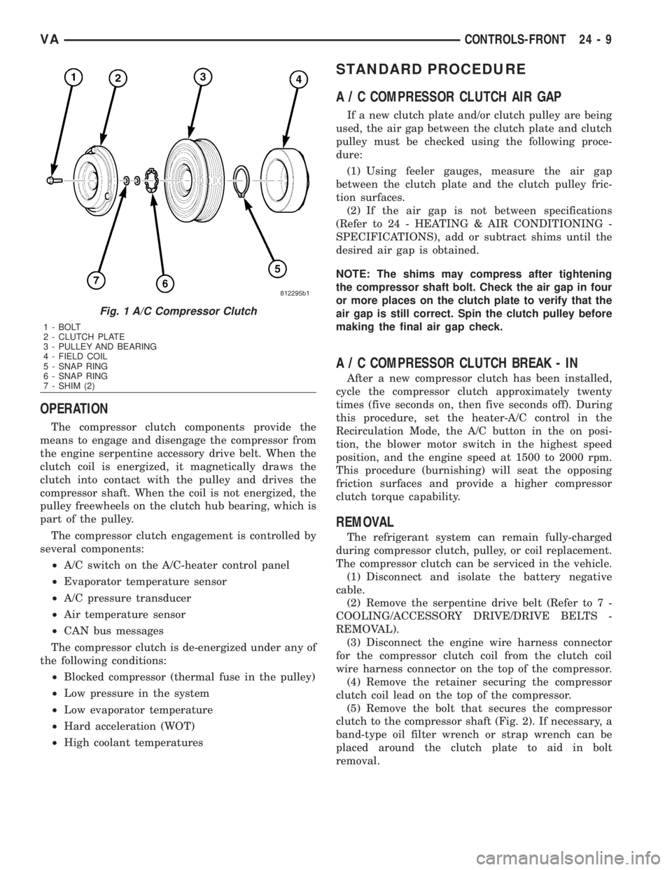
Fig. 1 A/C Compressor Clutch
1 - BOLT
2 - CLUTCH PLATE
3 - PULLEY AND BEARING
4 - FIELD COIL
5 - SNAP RING
6 - SNAP RING
7 - SHIM (2)
VACONTROLS-FRONT 24 - 9
Page 2049 of 2305
front cover of the compressor. Be certain that the
snap ring is properly fully and properly seated in the
groove.
(6) If the original clutch plate and clutch pulley
are to be reused, reinstall the original shim(s) on the
compressor shaft against the shoulder. If a new
clutch plate and/or clutch pulley are being used,
install a trial stack of shims 1.0 mm (0.040 in.) thick
on the compressor shaft against the shoulder.
(7) Install the clutch plate onto the compressor
shaft.
(8) Install and tighten the compressor shaft bolt. If
necessary, a band-type oil filter wrench or a strap
wrench can be placed around the clutch plate to aid
in bolt tightening. Tighten the bolt to 17.5 N´m (155
in. lbs.).
NOTE: The shims may compress after tightening
the shaft bolt. Check the air gap in four or more
places to verify the air gap is still correct. Spin the
pulley before performing a final check of the air
gap.
(9) If a new clutch plate and/or clutch pulley are
being installed, the air gap between the clutch plate
and clutch pulley must be checked (Refer to 24 -
HEATING & AIR CONDITIONING/CONTROLS/A/C
COMPRESSOR CLUTCH - STANDARD PROCE-
DURE).
(10) Install the retainer that secures the compres-
sor clutch coil lead to the top of the compressor.
(11) Reconnect the engine wire harness connector
to the clutch coil lead on the top of the compressor.
(12) Reinstall the serpentine accessory drive belt
(Refer to 7 - COOLING/ACCESSORY DRIVE/DRIVE
BELTS - INSTALLATION).
(13) Reconnect the battery negative cable.
(14) If a new clutch plate and/or clutch pulley are
being installed, the new clutch components must be
burnished (Refer to 24 - HEATING & AIR CONDI-
TIONING/CONTROLS/A/C COMPRESSOR CLUTCH
- STANDARD PROCEDURE).
A / C COMPRESSOR CLUTCH
COIL
DIAGNOSIS AND TESTING
A / C COMPRESSOR CLUTCH COIL
The air conditioning compressor clutch coil electri-
cal circuit is controlled by the ATC control module
which is integral to the heater-A/C control. Begin
testing of a suspected compressor clutch coil problem
by performing the ATC Function Test using the
DRBIIItscan tool.PRELIMINARY CHECKS
(1) If no diagnostic trouble codes (DTCs) are found
in the A/C-heater control or the powertrain control
module (PCM), go to Step 2. If any DTCs are found,
repair as required.
(2) If the A/C compressor clutch still will not
engage, verify the refrigerant charge level (Refer to
24 - HEATING & AIR CONDITIONING/PLUMBING
- DIAGNOSIS AND TESTING - REFRIGERANT
SYSTEM LEAKS). If the refrigerant charge level is
OK, go to TESTS. If the refrigerant charge level is
not OK, adjust the refrigerant charge as required.
TESTS
(1) Verify the battery state of charge (Refer to 8 -
ELECTRICAL/BATTERY SYSTEM/BATTERY -
DIAGNOSIS AND TESTING).
(2) Connect an ammeter (0 to 10 ampere scale
selected) in series with the clutch coil feed terminal.
Connect a voltmeter (0 to 20 volt scale selected) to
measure voltage across the battery and the clutch
coil.
(3) With the A/C-heater control in the A/C mode
and the blower motor at low speed, start the engine
and allow it to run at a normal idle speed.
(4) The A/C compressor clutch should engage
immediately, and the clutch coil supply voltage
should be within two volts of the battery voltage. If
the coil supply voltage is OK, go to Step 5. If the coil
supply voltage is not within two volts of battery volt-
age, test the clutch coil feed circuit for excessive volt-
age drop and repair as necessary.
(5) For the acceptable A/C clutch coil current draw
specifications refer to 24 - HEATING & AIR CONDI-
TIONING - SPECIFICATIONS. Specifications apply
for a work area temperature of 21É C (70É F). If volt-
age is more than 12.5 volts, add electrical loads by
turning on electrical accessories until voltage reads
below 12.5 volts.
(a) If the A/C clutch coil current reading is zero,
the coil is open and must be replaced.
(b) If the A/C clutch coil current reading is above
specifications, the coil is shorted and must be
replaced.
A / C HEATER CONTROL
DESCRIPTION
This ATC system uses a combination of electrical
and mechanical controls. These controls provide the
vehicle operator with a number of setting options to
help control the climate and comfort within the vehi-
cle.
The A/C-heater control is located on the instrument
panel inboard of the steering column and below the
24 - 12 CONTROLS-FRONTVA
Page 2061 of 2305
CONTROLS - REAR
TABLE OF CONTENTS
page page
A/C CLUTCH RELAY
DESCRIPTION.........................24
OPERATION...........................25
REMOVAL.............................25
INSTALLATION.........................26
A/C CONDENSER FAN RELAY
DESCRIPTION.........................26
OPERATION...........................26
REMOVAL.............................27
INSTALLATION.........................28
A/C CONTROL MODULE
DESCRIPTION.........................28
OPERATION...........................28
REMOVAL.............................29
INSTALLATION.........................30
A/C HIGH PRESSURE SWITCH
DESCRIPTION.........................30
OPERATION...........................30
REMOVAL.............................31
INSTALLATION.........................31
A/C LOW PRESSURE SWITCH
DESCRIPTION.........................32
OPERATION...........................32
REMOVAL.............................32
INSTALLATION.........................33
BLOWER MOTOR RELAY
DESCRIPTION.........................33
OPERATION...........................33
REMOVAL.............................34
INSTALLATION.........................35
BLOWER MOTOR SWITCH
DESCRIPTION.........................35
OPERATION...........................35
DIAGNOSIS AND TESTING
REAR BLOWER MOTOR SWITCH.........36REMOVAL.............................36
INSTALLATION.........................37
EVAPORATOR TEMPERATURE SENSOR
DESCRIPTION.........................37
OPERATION...........................37
REMOVAL.............................37
INSTALLATION.........................38
TEMPERATURE CONTROL
DESCRIPTION.........................38
OPERATION...........................38
DIAGNOSIS AND TESTING
REAR A/C TEMPERATURE CONTROL.....39
REMOVAL.............................39
INSTALLATION.........................40
TEMPERATURE SENSOR
DESCRIPTION.........................40
OPERATION...........................40
DIAGNOSIS AND TESTING
REAR TEMPERATURE SENSOR..........40
REMOVAL.............................40
INSTALLATION.........................41
SUPPRESSOR FILTER - REAR BLOWER
MOTOR
DESCRIPTION.........................41
OPERATION...........................41
REMOVAL.............................42
INSTALLATION.........................43
SUPPRESSOR FILTER - REAR CONDENSER
FA N
DESCRIPTION.........................43
OPERATION...........................44
REMOVAL.............................44
INSTALLATION.........................44
A / C CLUTCH RELAY
DESCRIPTION
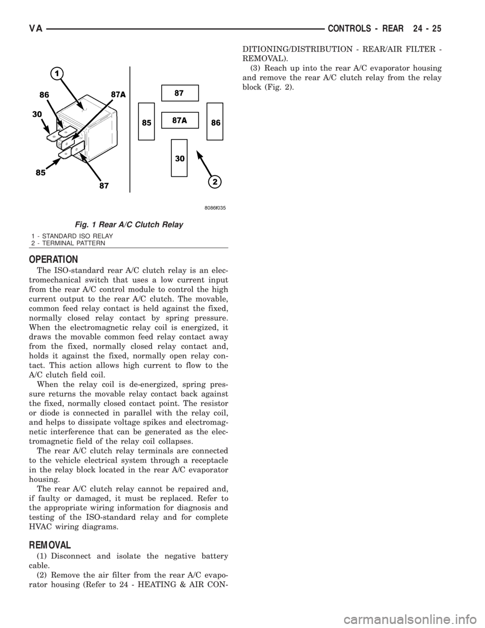
The rear A/C clutch relay for the rear A/C system
is an International Standards Organization (ISO)-
type relay (Fig. 1). Relays conforming to the ISO
specifications have common physical dimensions, cur-
rent capacities, terminal functions and patterns. The
rear A/C clutch relay is an electromechanical device
that uses a low current input controlled by the rear
A/C control module to control the high current output
to the A/C clutch field coil for the rear A/C system.The rear A/C clutch relay is located in the relay
block in the rear A/C evaporator housing.
24 - 24 CONTROLS - REARVA
Page 2062 of 2305
OPERATION
The ISO-standard rear A/C clutch relay is an elec-
tromechanical switch that uses a low current input
from the rear A/C control module to control the high
current output to the rear A/C clutch. The movable,
common feed relay contact is held against the fixed,
normally closed relay contact by spring pressure.
When the electromagnetic relay coil is energized, it
draws the movable common feed relay contact away
from the fixed, normally closed relay contact and,
holds it against the fixed, normally open relay con-
tact. This action allows high current to flow to the
A/C clutch field coil.
When the relay coil is de-energized, spring pres-
sure returns the movable relay contact back against
the fixed, normally closed contact point. The resistor
or diode is connected in parallel with the relay coil,
and helps to dissipate voltage spikes and electromag-
netic interference that can be generated as the elec-
tromagnetic field of the relay coil collapses.
The rear A/C clutch relay terminals are connected
to the vehicle electrical system through a receptacle
in the relay block located in the rear A/C evaporator
housing.
The rear A/C clutch relay cannot be repaired and,
if faulty or damaged, it must be replaced. Refer to
the appropriate wiring information for diagnosis and
testing of the ISO-standard relay and for complete
HVAC wiring diagrams.
REMOVAL
(1) Disconnect and isolate the negative battery
cable.
(2) Remove the air filter from the rear A/C evapo-
rator housing (Refer to 24 - HEATING & AIR CON-DITIONING/DISTRIBUTION - REAR/AIR FILTER -
REMOVAL).
(3) Reach up into the rear A/C evaporator housing
and remove the rear A/C clutch relay from the relay
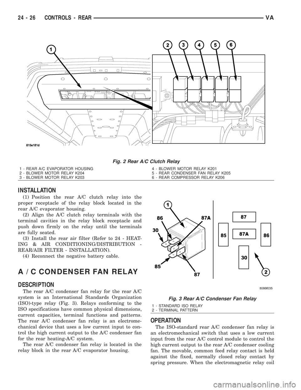
block (Fig. 2).
Fig. 1 Rear A/C Clutch Relay
1 - STANDARD ISO RELAY
2 - TERMINAL PATTERN
VACONTROLS - REAR 24 - 25
Page 2063 of 2305
INSTALLATION
(1) Position the rear A/C clutch relay into the
proper receptacle of the relay block located in the
rear A/C evaporator housing.
(2) Align the A/C clutch relay terminals with the
terminal cavities in the relay block receptacle and
push down firmly on the relay until the terminals
are fully seated.
(3) Install the rear air filter (Refer to 24 - HEAT-
ING & AIR CONDITIONING/DISTRIBUTION -
REAR/AIR FILTER - INSTALLATION).
(4) Reconnect the negative battery cable.
A / C CONDENSER FAN RELAY
DESCRIPTION
The rear A/C condenser fan relay for the rear A/C
system is an International Standards Organization
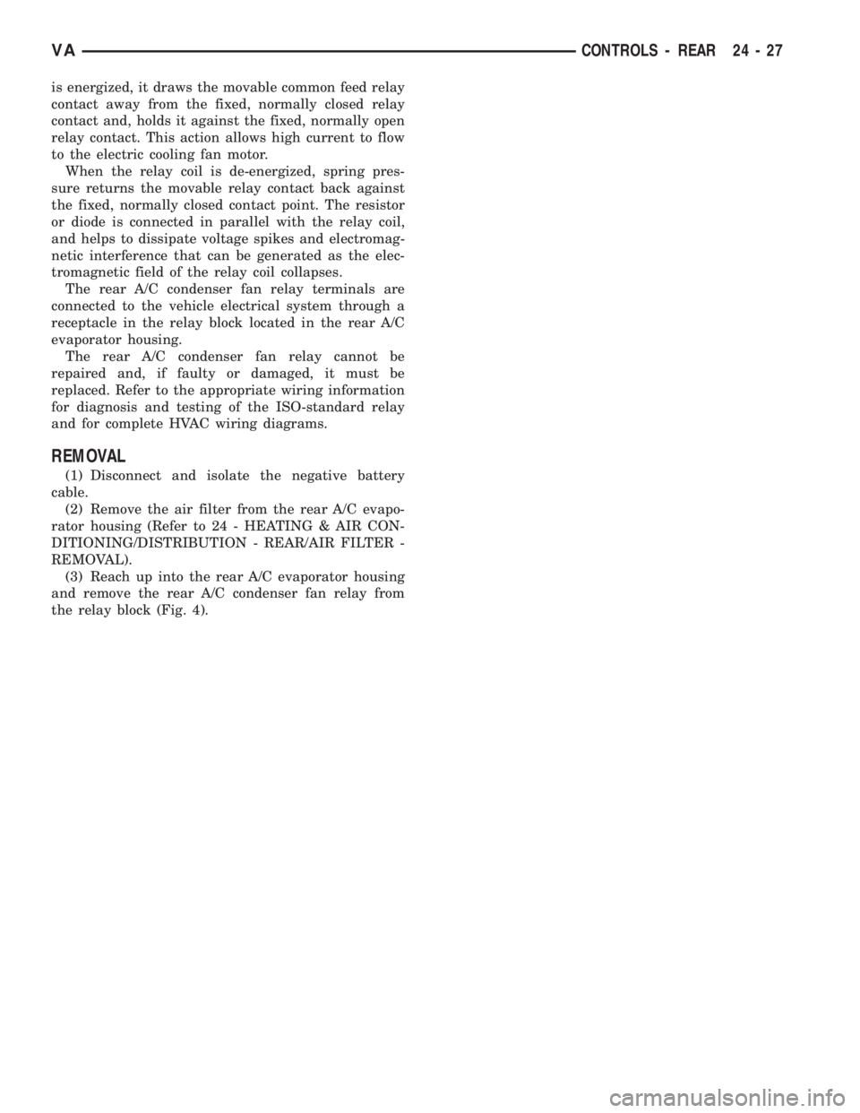
(ISO)-type relay (Fig. 3). Relays conforming to the
ISO specifications have common physical dimensions,
current capacities, terminal functions and patterns.
The rear A/C condenser fan relay is an electrome-
chanical device that uses a low current input to con-
trol the high current output to the A/C condenser fan
for the rear heating-A/C system.
The rear A/C condenser fan relay is located in the
relay block in the rear A/C evaporator housing.
OPERATION
The ISO-standard rear A/C condenser fan relay is
an electromechanical switch that uses a low current
input from the rear A/C control module to control the
high current output to the rear A/C condenser cooling
fan. The movable, common feed relay contact is held
against the fixed, normally closed relay contact by
spring pressure. When the electromagnetic relay coil
Fig. 2 Rear A/C Clutch Relay
1 - REAR A/C EVAPORATOR HOUSING
2 - BLOWER MOTOR RELAY K204
3 - BLOWER MOTOR RELAY K2034 - BLOWER MOTOR RELAY K201
5 - REAR CONDENSER FAN RELAY K205
6 - REAR COMPRESSOR RELAY K206
Fig. 3 Rear A/C Condenser Fan Relay
1 - STANDARD ISO RELAY
2 - TERMINAL PATTERN
24 - 26 CONTROLS - REARVA
Page 2064 of 2305
is energized, it draws the movable common feed relay
contact away from the fixed, normally closed relay
contact and, holds it against the fixed, normally open
relay contact. This action allows high current to flow
to the electric cooling fan motor.
When the relay coil is de-energized, spring pres-
sure returns the movable relay contact back against
the fixed, normally closed contact point. The resistor
or diode is connected in parallel with the relay coil,
and helps to dissipate voltage spikes and electromag-
netic interference that can be generated as the elec-
tromagnetic field of the relay coil collapses.
The rear A/C condenser fan relay terminals are
connected to the vehicle electrical system through a
receptacle in the relay block located in the rear A/C
evaporator housing.
The rear A/C condenser fan relay cannot be
repaired and, if faulty or damaged, it must be
replaced. Refer to the appropriate wiring information
for diagnosis and testing of the ISO-standard relay
and for complete HVAC wiring diagrams.
REMOVAL
(1) Disconnect and isolate the negative battery
cable.
(2) Remove the air filter from the rear A/C evapo-
rator housing (Refer to 24 - HEATING & AIR CON-
DITIONING/DISTRIBUTION - REAR/AIR FILTER -
REMOVAL).
(3) Reach up into the rear A/C evaporator housing
and remove the rear A/C condenser fan relay from
the relay block (Fig. 4).
VACONTROLS - REAR 24 - 27
Page 2071 of 2305
or diode is connected in parallel with the relay coil,
and helps to dissipate voltage spikes and electromag-
netic interference that can be generated as the elec-
tromagnetic field of the relay coil collapses.
The rear blower motor relay terminals are con-
nected to the vehicle electrical system through recep-
tacles in the relay block located in the rear A/C
evaporator housing.
The rear blower motor relays cannot be repaired
and, if faulty or damaged, they must be replaced.
Refer to the appropriate wiring information for diag-
nosis and testing of the ISO-standard relay and for
complete HVAC wiring diagrams.
REMOVAL
(1) Disconnect and isolate the negative battery
cable.
(2) Remove the air filter from the rear A/C evapo-
rator housing (Refer to 24 - HEATING & AIR CON-
DITIONING/DISTRIBUTION - REAR/AIR FILTER -
REMOVAL).
(3) Reach up into the rear A/C evaporator housing
and remove the rear blower motor relays as neces-
sary from the relay block (Fig. 12).
24 - 34 CONTROLS - REARVA
Page 2074 of 2305
INSTALLATION
(1) Install the rear A/C blower motor switch into
the accessory switch panel. Make sure the retaining
tabs are fully engaged.
(2) Connect the wire harness connector to the rear
A/C blower motor switch.
(3) Install the accessory switch panel (Refer to 23 -
BODY/INSTRUMENT PANEL/ACCESSORY
SWITCH BEZEL - INSTALLATION).
(4) Reconnect the negative battery cable.
EVAPORATOR TEMPERATURE
SENSOR
DESCRIPTION
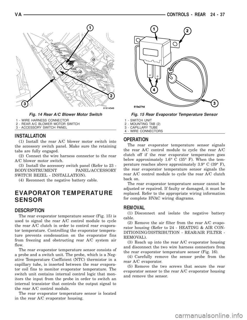
The rear evaporator temperature sensor (Fig. 15) is
used to signal the rear A/C control module to cycle
the rear A/C clutch in order to control rear evapora-
tor temperature. Controlling the evaporator tempera-
ture prevents condensation on the evaporator fins
from freezing and obstructing rear A/C system air
flow.
The rear evaporator temperature sensor consists of
a probe and a switch unit. The probe, which is a Neg-
ative Temperature Coefficient (NTC) thermistor in a
capillary tube, is inserted between the rear evapora-
tor coil fins to monitor evaporator temperature. The
switch unit contains internal control logic that mon-
itors the input from the probe in order to switch an
internal transistor that controls the output signal to
the rear A/C control module.
The rear evaporator temperature sensor is located
in the rear A/C evaporator housing.
OPERATION
The rear evaporator temperature sensor signals
the rear A/C control module to cycle the rear A/C
clutch off if the rear evaporator temperature goes
below approximately 1.6É C (35É F). When the tem-
perature reaches above approximately 3.9É C (39É F),
the rear evaporator temperature sensor signals the
rear A/C control module to cycle the rear A/C clutch
back on.
The rear evaporator temperature sensor cannot be
adjusted or repaired. If faulty or damaged, it must be
replaced. Refer to the appropriate wiring information
for complete HVAC wiring diagrams.
REMOVAL
(1) Disconnect and isolate the negative battery
cable.
(2) Remove the air filter from the rear A/C evapo-
rator housing (Refer to 24 - HEATING & AIR CON-
DITIONING/DISTRIBUTION - REAR/AIR FILTER -
REMOVAL).
(3) Reach up into the rear A/C evaporator housing
and disconnect the two wire harness connectors from
the rear evaporator temperature sensor (Fig. 16).
(4) Carefully remove the sensor probe from the
rear A/C evaporator.
(5) Remove the two screws that secure the rear
evaporator sensor to the rear A/C evaporator housing
and remove the sensor.
Fig. 14 Rear A/C Blower Motor Switch
1 - WIRE HARNESS CONNECTOR
2 - REAR A/C BLOWER MOTOR SWITCH
3 - ACCESSORY SWITCH PANEL
Fig. 15 Rear Evaporator Temperature Sensor
1 - SWITCH UNIT
2 - MOUNTING TAB (2)
3 - CAPILLARY TUBE
4 - WIRE CONNECTORS
VACONTROLS - REAR 24 - 37