Page 243 of 2305
TEST ACTION APPLICABILITY
3 Turn the ignition off.
Disconnect the Rear Door Jamb Switch connector.
Ensure the sliding door(s) are closed or the switches are disconnected.
Observe the courtesy lamps.
Did the courtesy lamps go off?All
Ye s!Replace the Rear Door Jamb Switch.
Perform BODY VERIFICATION TEST - VER 1.
No!Go To 4
4 Turn the ignition off.
Disconnect the Security System Module C1 connector.
Ensure the sliding and rear doors are closed or the switches are disconnected.
Observe the courtesy lamps.
Did the courtesy lamps go off?All
Ye s!Replace the Security System Module in accordance with service
information.
Perform BODY VERIFICATION TEST - VER 1.
No!Repair the Rear Courtesy Lamps Control circuit for a short to
ground.
Perform BODY VERIFICATION TEST - VER 1.
230
VEHICLE THEFT/SECURITY
REAR OR SLIDING DOOR JAMB SWITCH CIRCUIT SHORT TO GROUND
Ð
Continued
Page 244 of 2305
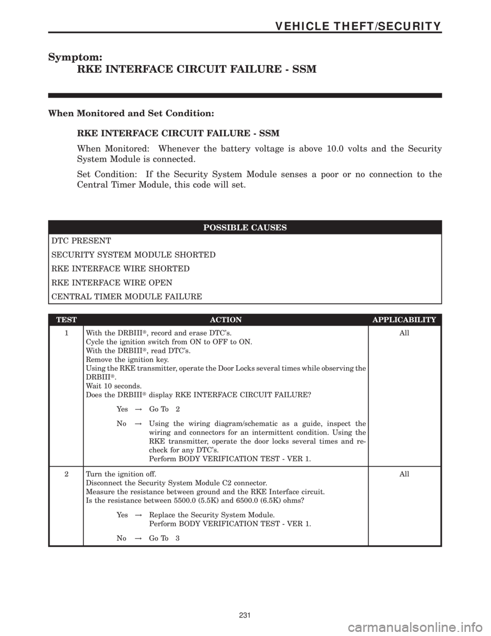
Symptom:
RKE INTERFACE CIRCUIT FAILURE - SSM
When Monitored and Set Condition:
RKE INTERFACE CIRCUIT FAILURE - SSM
When Monitored: Whenever the battery voltage is above 10.0 volts and the Security
System Module is connected.
Set Condition: If the Security System Module senses a poor or no connection to the
Central Timer Module, this code will set.
POSSIBLE CAUSES
DTC PRESENT
SECURITY SYSTEM MODULE SHORTED
RKE INTERFACE WIRE SHORTED
RKE INTERFACE WIRE OPEN
CENTRAL TIMER MODULE FAILURE
TEST ACTION APPLICABILITY
1 With the DRBIIIt, record and erase DTC's.
Cycle the ignition switch from ON to OFF to ON.
With the DRBIIIt, read DTC's.
Remove the ignition key.
Using the RKE transmitter, operate the Door Locks several times while observing the
DRBIIIt.
Wait 10 seconds.
Does the DRBIIItdisplay RKE INTERFACE CIRCUIT FAILURE?All
Ye s!Go To 2
No!Using the wiring diagram/schematic as a guide, inspect the
wiring and connectors for an intermittent condition. Using the
RKE transmitter, operate the door locks several times and re-
check for any DTC's.
Perform BODY VERIFICATION TEST - VER 1.
2 Turn the ignition off.
Disconnect the Security System Module C2 connector.
Measure the resistance between ground and the RKE Interface circuit.
Is the resistance between 5500.0 (5.5K) and 6500.0 (6.5K) ohms?All
Ye s!Replace the Security System Module.
Perform BODY VERIFICATION TEST - VER 1.
No!Go To 3
231
VEHICLE THEFT/SECURITY
Page 246 of 2305
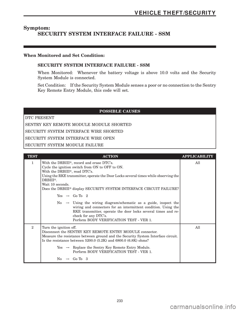
Symptom:
SECURITY SYSTEM INTERFACE FAILURE - SSM
When Monitored and Set Condition:
SECURITY SYSTEM INTERFACE FAILURE - SSM
When Monitored: Whenever the battery voltage is above 10.0 volts and the Security
System Module is connected.
Set Condition: If the Security System Module senses a poor or no connection to the Sentry
Key Remote Entry Module, this code will set.
POSSIBLE CAUSES
DTC PRESENT
SENTRY KEY REMOTE MODULE MODULE SHORTED
SECURITY SYSTEM INTERFACE WIRE SHORTED
SECURITY SYSTEM INTERFACE WIRE OPEN
SECURITY SYSTEM MODULE FAILURE
TEST ACTION APPLICABILITY
1 With the DRBIIIt, record and erase DTC's.
Cycle the ignition switch from ON to OFF to ON.
With the DRBIIIt, read DTC's.
Using the RKE transmitter, operate the Door Locks several times while observing the
DRBIIIt.
Wait 10 seconds.
Does the DRBIIItdisplay SECURITY SYSTEM INTERFACE CIRCUIT FAILURE?All
Ye s!Go To 2
No!Using the wiring diagram/schematic as a guide, inspect the
wiring and connectors for an intermittent condition. Using the
RKE transmitter, operate the door locks several times and re-
check for any DTC's.
Perform BODY VERIFICATION TEST - VER 1.
2 Turn the ignition off.
Disconnect the SENTRY KEY REMOTE ENTRY MODULE connector.
Measure the resistance between ground and the Security System Interface circuit.
Is the resistance between 5200.0 (5.2K) and 6800.0 (6.8K) ohms?All
Ye s!Replace the Sentry Key Remote Entry Module.
Perform BODY VERIFICATION TEST - VER 1.
No!Go To 3
233
VEHICLE THEFT/SECURITY
Page 248 of 2305
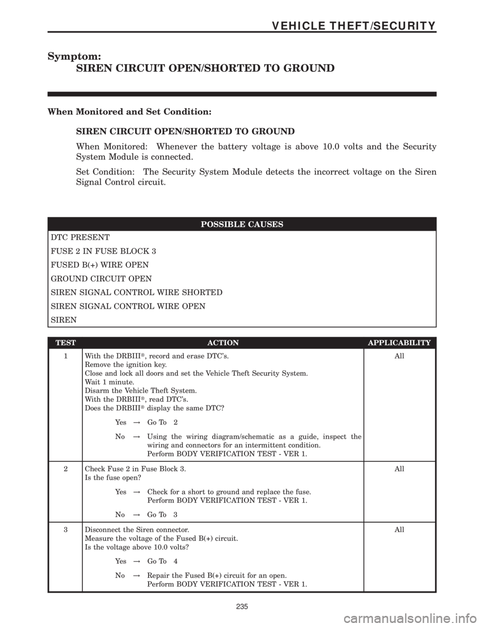
Symptom:
SIREN CIRCUIT OPEN/SHORTED TO GROUND
When Monitored and Set Condition:
SIREN CIRCUIT OPEN/SHORTED TO GROUND
When Monitored: Whenever the battery voltage is above 10.0 volts and the Security
System Module is connected.
Set Condition: The Security System Module detects the incorrect voltage on the Siren
Signal Control circuit.
POSSIBLE CAUSES
DTC PRESENT
FUSE 2 IN FUSE BLOCK 3
FUSED B(+) WIRE OPEN
GROUND CIRCUIT OPEN
SIREN SIGNAL CONTROL WIRE SHORTED
SIREN SIGNAL CONTROL WIRE OPEN
SIREN
TEST ACTION APPLICABILITY
1 With the DRBIIIt, record and erase DTC's.
Remove the ignition key.
Close and lock all doors and set the Vehicle Theft Security System.
Wait 1 minute.
Disarm the Vehicle Theft System.
With the DRBIIIt, read DTC's.
Does the DRBIIItdisplay the same DTC?All
Ye s!Go To 2
No!Using the wiring diagram/schematic as a guide, inspect the
wiring and connectors for an intermittent condition.
Perform BODY VERIFICATION TEST - VER 1.
2 Check Fuse 2 in Fuse Block 3.
Is the fuse open?All
Ye s!Check for a short to ground and replace the fuse.
Perform BODY VERIFICATION TEST - VER 1.
No!Go To 3
3 Disconnect the Siren connector.
Measure the voltage of the Fused B(+) circuit.
Is the voltage above 10.0 volts?All
Ye s!Go To 4
No!Repair the Fused B(+) circuit for an open.
Perform BODY VERIFICATION TEST - VER 1.
235
VEHICLE THEFT/SECURITY
Page 250 of 2305
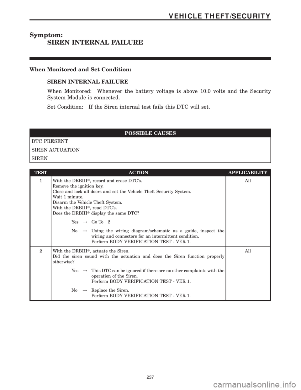
Symptom:
SIREN INTERNAL FAILURE
When Monitored and Set Condition:
SIREN INTERNAL FAILURE
When Monitored: Whenever the battery voltage is above 10.0 volts and the Security
System Module is connected.
Set Condition: If the Siren internal test fails this DTC will set.
POSSIBLE CAUSES
DTC PRESENT
SIREN ACTUATION
SIREN
TEST ACTION APPLICABILITY
1 With the DRBIIIt, record and erase DTC's.
Remove the ignition key.
Close and lock all doors and set the Vehicle Theft Security System.
Wait 1 minute.
Disarm the Vehicle Theft System.
With the DRBIIIt, read DTC's.
Does the DRBIIItdisplay the same DTC?All
Ye s!Go To 2
No!Using the wiring diagram/schematic as a guide, inspect the
wiring and connectors for an intermittent condition.
Perform BODY VERIFICATION TEST - VER 1.
2 With the DRBIIIt, actuate the Siren.
Did the siren sound with the actuation and does the Siren function properly
otherwise?All
Ye s!This DTC can be ignored if there are no other complaints with the
operation of the Siren.
Perform BODY VERIFICATION TEST - VER 1.
No!Replace the Siren.
Perform BODY VERIFICATION TEST - VER 1.
237
VEHICLE THEFT/SECURITY
Page 251 of 2305
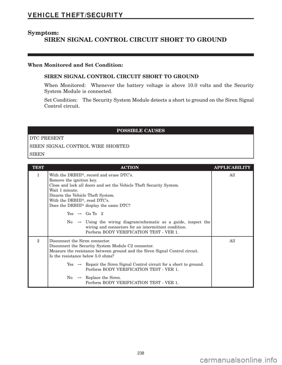
Symptom:
SIREN SIGNAL CONTROL CIRCUIT SHORT TO GROUND
When Monitored and Set Condition:
SIREN SIGNAL CONTROL CIRCUIT SHORT TO GROUND
When Monitored: Whenever the battery voltage is above 10.0 volts and the Security
System Module is connected.
Set Condition: The Security System Module detects a short to ground on the Siren Signal
Control circuit.
POSSIBLE CAUSES
DTC PRESENT
SIREN SIGNAL CONTROL WIRE SHORTED
SIREN
TEST ACTION APPLICABILITY
1 With the DRBIIIt, record and erase DTC's.
Remove the ignition key.
Close and lock all doors and set the Vehicle Theft Security System.
Wait 1 minute.
Disarm the Vehicle Theft System.
With the DRBIIIt, read DTC's.
Does the DRBIIItdisplay the same DTC?All
Ye s!Go To 2
No!Using the wiring diagram/schematic as a guide, inspect the
wiring and connectors for an intermittent condition.
Perform BODY VERIFICATION TEST - VER 1.
2 Disconnect the Siren connector.
Disconnect the Security System Module C2 connector.
Measure the resistance between ground and the Siren Signal Control circuit.
Is the resistance below 5.0 ohms?All
Ye s!Repair the Siren Signal Control circuit for a short to ground.
Perform BODY VERIFICATION TEST - VER 1.
No!Replace the Siren.
Perform BODY VERIFICATION TEST - VER 1.
238
VEHICLE THEFT/SECURITY
Page 252 of 2305

Symptom:
CHECKING THE RAIN SENSOR/WIPER OPERATION
POSSIBLE CAUSES
CHECK THE WIPER MOTOR CIRCUIT CAVITY 2
CHECK THE WIPER MOTOR CIRCUIT CAVITY 5
CHECK THE WIPER MOTOR CIRCUIT CAVITY 5 II
CHECK THE WIPER MOTOR CIRCUIT CAVITY 6
CHECK THE WIPER MOTOR CIRCUIT CAVITY 6 II
CHECK WIPER MOTOR GROUND CIRCUIT
CHECKING THE 12 VOLT POWER SUPPLY
CHECKING THE GROUND CIRCUIT
CHECKING THE RAIN SENSOR OPERATION
CHECKING WIPER SIGNALS TO THE RAIN SENSOR MODULE
RAIN SENSOR
RAIN SENSOR CIRCUIT(S) OPEN
RAIN SENSOR CIRCUIT(S) SHORTED TO GROUND
RAIN SENSOR CIRCUIT(S) SHORTED TO VOLTAGE
RAIN SENSOR MODULE
RAIN SNSR CKTS SHORTED TOGETHER
WIPER MOTOR
TEST ACTION APPLICABILITY
1 Turn the ignition on.
Monitor the windshield wipers while turning the wiper switch to each of the 4 switch
positions: OFF, INTERMITTENT, LOW and HIGH.
Did the wipers functions properly in each wiper switch position?All
Ye s!Go To 2
No!Go To 8
2NOTE: The Rain Sensor is located in the windshield mount of the rear view
mirror in the top-center of the windshield.
NOTE: The Rain Sensor Module (RSM) is mounted above the accelerator
pedal assembly.
Turn the ignition on.
Move the Wiper Switch to the Intermittent position.
Spray or pour water on the Rain Sensor area of the windshield.
Did the wipers activate when water was sprayed/poured on the Rain Sensor area of
the windshield?All
Ye s!Rain Sensor/Wiper System operating properly. Test complete.
No!Go To 3
239
WINDSHIELD WIPER & WASHER
Page 253 of 2305

TEST ACTION APPLICABILITY
3 Turn the ignition off.
Disconnect the Rain Sensor Module harness connector.
Measure the resistance between ground and each of the Rain Sensor circuits at the
Rain Sensor Module harness connector.
Is the resistance above 1000 ohms for each measurement?All
Ye s!Go To 4
No!Repair the circuit(s) that measured below 1000 ohms for a short to
ground.
4 Turn the ignition off.
Disconnect the Rain Sensor Module harness connector.
Turn the ignition on.
Measure the voltage of each of the Rain Sensor circuits at the Rain Sensor Module
harness connector.
Is the voltage below 1.0 volt for each measurement?All
Ye s!Go To 5
No!Repair the circuit(s) that measured above 1.0 volt for a short to
voltage.
5 Turn the ignition off.
Disconnect the Rain Sensor harness connector.
Disconnect the Rain Sensor Module harness connector.
Measure the resistance of each Rain Sensor circuit between the Rain Sensor Module
harness connector and the Rain Sensor harness connector.
Is the resistance below 10.0 ohms for each measurement?All
Ye s!Go To 6
No!Repair the circuit(s) that measured above 10.0 ohms for an open.
6 Turn the ignition off.
Disconnect the Rain Sensor harness connector.
Disconnect the Rain Sensor Module harness connector.
Measure the resistance between Rain Sensor harness connector cavities 1 and 2.
Repeat this step for cavities 1 and 3, cavities 2 and 3.
Is the resistance above 1000 ohms for each measurement?All
Ye s!Go To 7
No!Repair the circuit(s) that measured below 1000 ohms for a short
together.
7 Turn the ignition off.
Replace the Rain Sensor in accordance with the Service Information.
Turn the ignition on.
Move the Wiper Switch to the Intermittent position.
Spray or pour water on the Rain Sensor area of the windshield.
NOTE: The Rain Sensor is located in the windshield mount of the rear view
mirror in the top-center of the windshield.
Did the wipers activate when water was sprayed/poured on the Rain Sensor area of
the windshield?All
Ye s!Replace the original Rain Sensor in accordance with the Service
Information.
No!Replace the Rain Sensor Module in accordance with the Service
Information.
240
WINDSHIELD WIPER & WASHER
CHECKING THE RAIN SENSOR/WIPER OPERATION ÐContinued