2006 MERCEDES-BENZ SPRINTER ESP
[x] Cancel search: ESPPage 2011 of 2305
INSTALLATION
WARNING: ON VEHICLES EQUIPPED WITH AIR-
BAGS, DISABLE THE AIRBAG SYSTEM BEFORE
ATTEMPTING ANY STEERING WHEEL, STEERING
COLUMN, SEAT BELT TENSIONER, OR INSTRU-
MENT PANEL COMPONENT DIAGNOSIS OR SER-
VICE. DISCONNECT AND ISOLATE THE BATTERY
NEGATIVE (GROUND) CABLE, THEN WAIT TWO
MINUTES FOR THE AIRBAG SYSTEM CAPACITOR
TO DISCHARGE BEFORE PERFORMING FURTHER
DIAGNOSIS OR SERVICE. THIS IS THE ONLY SURE
WAY TO DISABLE THE AIRBAG SYSTEM. FAILURE
TO TAKE THE PROPER PRECAUTIONS COULD
RESULT IN ACCIDENTAL AIRBAG DEPLOYMENT
AND POSSIBLE PERSONAL INJURY.
²WHEN REMOVING A DEPLOYED AIRBAG, RUB-
BER GLOVES, EYE PROTECTION, AND A LONG-
SLEEVED SHIRT SHOULD BE WORN. THERE MAY
BE DEPOSITS ON THE AIRBAG UNIT AND OTHER
INTERIOR SURFACES. IN LARGE DOSES, THESE
DEPOSITS MAY CAUSE IRRITATION TO THE SKIN
AND EYES.
²USE EXTREME CARE TO PREVENT ANY FOR-
EIGN MATERIAL FROM ENTERING THE PASSEN-
GER AIRBAG, OR BECOMING ENTRAPPED
BETWEEN THE PASSENGER AIRBAG CUSHIONAND THE PASSENGER AIRBAG DOOR. FAILURE TO
OBSERVE THIS WARNING COULD RESULT IN
OCCUPANT INJURIES UPON AIRBAG DEPLOY-
MENT.
²THE PASSENGER AIRBAG DOOR MUST
NEVER BE PAINTED. REPLACEMENT PASSENGER
AIRBAGS ARE SERVICED WITH DOORS IN THE
ORIGINAL COLORS. PAINT MAY CHANGE THE WAY
IN WHICH THE MATERIAL OF THE AIRBAG DOOR
RESPONDS TO AN AIRBAG DEPLOYMENT. FAIL-
URE TO OBSERVE THIS WARNING COULD RESULT
IN OCCUPANT INJURIES UPON AIRBAG DEPLOY-
MENT.
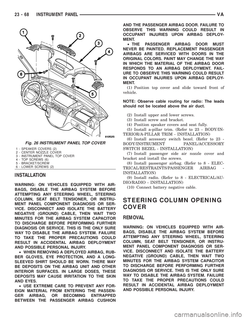
(1) Position top cover and slide toward front of
vehicle.
NOTE: Observe cable routing for radio: The leads
should not be located above the air duct.
(2) Install upper and lower screws.
(3) Install screw and bracket.
(4) Position speaker covers and seat fully.
(5) Install a-pillar trim. (Refer to 23 - BODY/IN-
TERIOR/A-PILLAR TRIM - INSTALLATION)
(6) Install accessory switch bezel. (Refer to 23 -
BODY/INSTRUMENT PANEL/ACCESSORY
SWITCH BEZEL - INSTALLATION)
(7) Install passenger side air nozzle cover and
bracket and install the screws.
(8) Install passenger airbag. (Refer to 8 - ELEC-
TRICAL/RESTRAINTS/PASSENGER AIRBAG -
INSTALLATION)
(9) Install radio. (Refer to 8 - ELECTRICAL/AU-
DIO/RADIO - INSTALLATION)
(10) Connect battery negative cable.
STEERING COLUMN OPENING
COVER
REMOVAL
WARNING: ON VEHICLES EQUIPPED WITH AIR-
BAGS, DISABLE THE AIRBAG SYSTEM BEFORE
ATTEMPTING ANY STEERING WHEEL, STEERING
COLUMN, SEAT BELT TENSIONER, OR INSTRU-
MENT PANEL COMPONENT DIAGNOSIS OR SER-
VICE. DISCONNECT AND ISOLATE THE BATTERY
NEGATIVE (GROUND) CABLE, THEN WAIT TWO
MINUTES FOR THE AIRBAG SYSTEM CAPACITOR
TO DISCHARGE BEFORE PERFORMING FURTHER
DIAGNOSIS OR SERVICE. THIS IS THE ONLY SURE
WAY TO DISABLE THE AIRBAG SYSTEM. FAILURE
TO TAKE THE PROPER PRECAUTIONS COULD
RESULT IN ACCIDENTAL AIRBAG DEPLOYMENT
AND POSSIBLE PERSONAL INJURY.
Fig. 26 INSTRUMENT PANEL TOP COVER
1 - SPEAKER COVERS (2)
2 - CENTER NOZZLE COVER
3 - INSTRUMENT PANEL TOP COVER
4 - TOP SCREWS (6)
5 - BRACKET/SCREW
6 - LOWER SCREWS (2)
23 - 68 INSTRUMENT PANELVA
Page 2020 of 2305
PAINT
TABLE OF CONTENTS
page page
PAINT
SPECIFICATIONS - PAINT CODES..........77
BASECOAT/CLEARCOAT FINISH
DESCRIPTION.........................77
PAINT TOUCH-UP
DESCRIPTION.........................77STANDARD PROCEDURE - PAINT TOUCH-UP . 77
FINESSE SANDING/BUFFING & POLISH
DESCRIPTION.........................78
PAINT
SPECIFICATIONS - PAINT CODES
EXTERIOR COLORS
EXTERIOR COLOR DAIMLERCHRYSLER
CODE
Steel Blue MB 5389
Brilliant Blue MB 5362
Orchid Green MB 6464
Flame Red MB 3534
Arctic White MB 9147
Black Blue MB 7103
Calcite Yellow MB 1234
Piedmont Red MB 3636
Hycanith Blue MB 5376
Black Gray MB 7103
Stone Gray MB 7160
Silver Gray MB 7708
BASECOAT / CLEARCOAT FIN-
ISH
DESCRIPTION
The original equipment finish is a multi step pro-
cess that involves cleaning, applying electro de-posi-
tion (E-coat), anti-chip primer, basecoat, and
clearcoat steps.
On most vehicles a two-part paint application
(basecoat/clearcoat) is used. Color paint that is
applied to primer is called basecoat. The clear coat
protects the basecoat from ultraviolet light and pro-
vides a durable high-gloss finish.
CAUTION: Do not use abrasive chemicals or com-
pounds on painted surfaces. Damage to finish can
result.Do not use harsh alkaline based cleaning solvents
on painted surfaces. Damage to finish or color can
result.
PAINT TOUCH - UP
DESCRIPTION
When a painted metal surface has been scratched
or chipped, it should be touched-up as soon as possi-
ble to avoid corrosion. For best results, use MOPARt
Scratch Filler/Primer, Touch-Up Paints and Clear Top
Coat.
WARNING: USE AN OSHA APPROVED RESPIRATOR
AND SAFETY GLASSES WHEN SPRAYING PAINT
OR SOLVENTS IN A CONFINED AREA. PERSONAL
INJURY CAN RESULT.
STANDARD PROCEDURE - PAINT TOUCH - UP
(1) Scrape loose paint and corrosion from inside
scratch or chip.
(2) Clean affected area with MOPARtTar/Road
Oil Remover or equivalent, and allow to dry.
(3) Fill the inside of the scratch or chip with a coat
of filler/primer. Do not overlap primer onto good sur-
face finish. The applicator brush should be wet
enough to puddle-fill the scratch or chip without run-
ning. Do not stroke brush applicator on body surface.
Allow the filler/primer to dry hard.
(4) Cover the filler/primer with color touch-up
paint. Do not overlap touch-up color onto the original
color coat around the scratch or chip. Butt the new
color to the original color, if possible. Do not stroke
applicator brush on body surface. Allow touch-up
paint to dry hard.
(5) On vehicles without clearcoat, the touch-up
color can be lightly finesse sanded (1500 grit) and
polished with rubbing compound.
(6) On vehicles with clearcoat, apply clear top coat
to touch-up paint with the same technique as
VAPAINT 23 - 77
Page 2025 of 2305
INSTALLATION
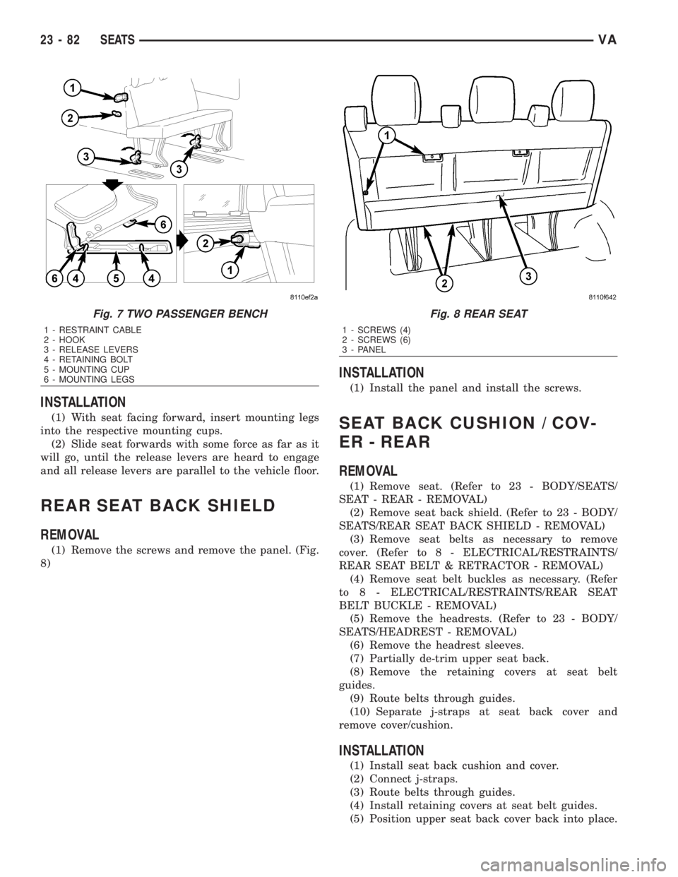
(1) With seat facing forward, insert mounting legs
into the respective mounting cups.
(2) Slide seat forwards with some force as far as it
will go, until the release levers are heard to engage
and all release levers are parallel to the vehicle floor.
REAR SEAT BACK SHIELD
REMOVAL
(1) Remove the screws and remove the panel. (Fig.
8)
INSTALLATION
(1) Install the panel and install the screws.
SEAT BACK CUSHION / COV-
ER - REAR
REMOVAL
(1) Remove seat. (Refer to 23 - BODY/SEATS/
SEAT - REAR - REMOVAL)
(2) Remove seat back shield. (Refer to 23 - BODY/
SEATS/REAR SEAT BACK SHIELD - REMOVAL)
(3) Remove seat belts as necessary to remove
cover. (Refer to 8 - ELECTRICAL/RESTRAINTS/
REAR SEAT BELT & RETRACTOR - REMOVAL)
(4) Remove seat belt buckles as necessary. (Refer
to 8 - ELECTRICAL/RESTRAINTS/REAR SEAT
BELT BUCKLE - REMOVAL)
(5) Remove the headrests. (Refer to 23 - BODY/
SEATS/HEADREST - REMOVAL)
(6) Remove the headrest sleeves.
(7) Partially de-trim upper seat back.
(8) Remove the retaining covers at seat belt
guides.
(9) Route belts through guides.
(10) Separate j-straps at seat back cover and
remove cover/cushion.
INSTALLATION
(1) Install seat back cushion and cover.
(2) Connect j-straps.
(3) Route belts through guides.
(4) Install retaining covers at seat belt guides.
(5) Position upper seat back cover back into place.
Fig. 7 TWO PASSENGER BENCH
1 - RESTRAINT CABLE
2 - HOOK
3 - RELEASE LEVERS
4 - RETAINING BOLT
5 - MOUNTING CUP
6 - MOUNTING LEGS
Fig. 8 REAR SEAT
1 - SCREWS (4)
2 - SCREWS (6)
3 - PANEL
23 - 82 SEATSVA
Page 2051 of 2305
(5) Install the two A/C-heater control retaining
screws. Tighten the screws to 2 N´m (17 in. lbs.).
(6) Install the center bezel onto the instrument
panel (Refer to 23 - BODY/INSTRUMENT PANEL/
INSTRUMENT PANEL CENTER BEZEL - INSTAL-
LATION).
(7) Reconnect the negative battery cable.
A / C PRESSURE TRANS-
DUCER
DESCRIPTION
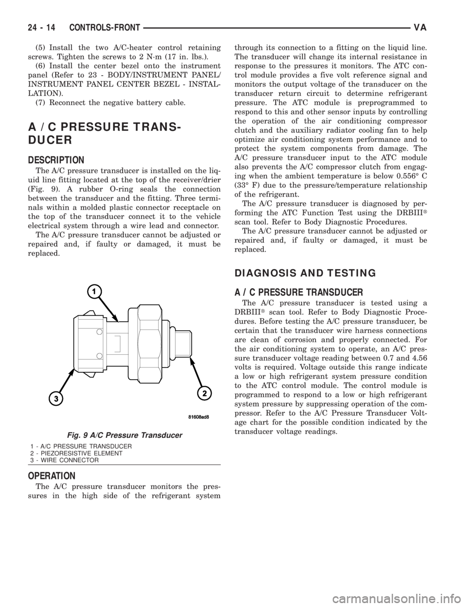
The A/C pressure transducer is installed on the liq-
uid line fitting located at the top of the receiver/drier
(Fig. 9). A rubber O-ring seals the connection
between the transducer and the fitting. Three termi-
nals within a molded plastic connector receptacle on
the top of the transducer connect it to the vehicle
electrical system through a wire lead and connector.
The A/C pressure transducer cannot be adjusted or
repaired and, if faulty or damaged, it must be
replaced.
OPERATION
The A/C pressure transducer monitors the pres-
sures in the high side of the refrigerant systemthrough its connection to a fitting on the liquid line.
The transducer will change its internal resistance in
response to the pressures it monitors. The ATC con-
trol module provides a five volt reference signal and
monitors the output voltage of the transducer on the
transducer return circuit to determine refrigerant
pressure. The ATC module is preprogrammed to
respond to this and other sensor inputs by controlling
the operation of the air conditioning compressor
clutch and the auxiliary radiator cooling fan to help
optimize air conditioning system performance and to
protect the system components from damage. The
A/C pressure transducer input to the ATC module
also prevents the A/C compressor clutch from engag-
ing when the ambient temperature is below 0.556É C
(33É F) due to the pressure/temperature relationship
of the refrigerant.
The A/C pressure transducer is diagnosed by per-
forming the ATC Function Test using the DRBIIIt
scan tool. Refer to Body Diagnostic Procedures.
The A/C pressure transducer cannot be adjusted or
repaired and, if faulty or damaged, it must be
replaced.
DIAGNOSIS AND TESTING
A / C PRESSURE TRANSDUCER
The A/C pressure transducer is tested using a
DRBIIItscan tool. Refer to Body Diagnostic Proce-
dures. Before testing the A/C pressure transducer, be
certain that the transducer wire harness connections
are clean of corrosion and properly connected. For
the air conditioning system to operate, an A/C pres-
sure transducer voltage reading between 0.7 and 4.56
volts is required. Voltage outside this range indicate
a low or high refrigerant system pressure condition
to the ATC control module. The control module is
programmed to respond to a low or high refrigerant
system pressure by suppressing operation of the com-
pressor. Refer to the A/C Pressure Transducer Volt-
age chart for the possible condition indicated by the
transducer voltage readings.
Fig. 9 A/C Pressure Transducer
1 - A/C PRESSURE TRANSDUCER
2 - PIEZORESISTIVE ELEMENT
3 - WIRE CONNECTOR
24 - 14 CONTROLS-FRONTVA
Page 2053 of 2305
(6) Charge the refrigerant system (Refer to 24 -
HEATING & AIR CONDITIONING/PLUMBING -
STANDARD PROCEDURE).
AIR OUTLET TEMPERATURE
SENSOR
DESCRIPTION
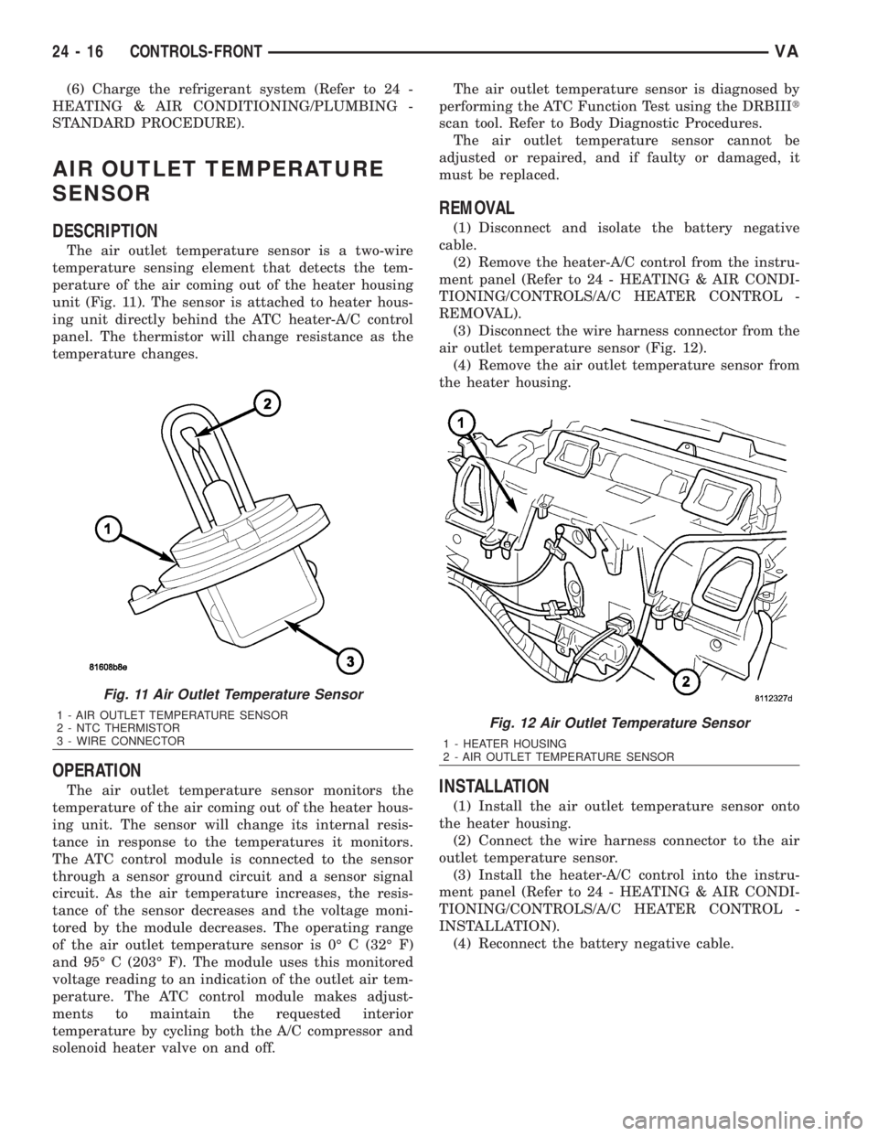
The air outlet temperature sensor is a two-wire
temperature sensing element that detects the tem-
perature of the air coming out of the heater housing
unit (Fig. 11). The sensor is attached to heater hous-
ing unit directly behind the ATC heater-A/C control
panel. The thermistor will change resistance as the
temperature changes.
OPERATION
The air outlet temperature sensor monitors the
temperature of the air coming out of the heater hous-
ing unit. The sensor will change its internal resis-
tance in response to the temperatures it monitors.
The ATC control module is connected to the sensor
through a sensor ground circuit and a sensor signal
circuit. As the air temperature increases, the resis-
tance of the sensor decreases and the voltage moni-
tored by the module decreases. The operating range
of the air outlet temperature sensor is 0É C (32É F)
and 95É C (203É F). The module uses this monitored
voltage reading to an indication of the outlet air tem-
perature. The ATC control module makes adjust-
ments to maintain the requested interior
temperature by cycling both the A/C compressor and
solenoid heater valve on and off.The air outlet temperature sensor is diagnosed by
performing the ATC Function Test using the DRBIIIt
scan tool. Refer to Body Diagnostic Procedures.
The air outlet temperature sensor cannot be
adjusted or repaired, and if faulty or damaged, it
must be replaced.
REMOVAL
(1) Disconnect and isolate the battery negative
cable.
(2) Remove the heater-A/C control from the instru-
ment panel (Refer to 24 - HEATING & AIR CONDI-
TIONING/CONTROLS/A/C HEATER CONTROL -
REMOVAL).
(3) Disconnect the wire harness connector from the
air outlet temperature sensor (Fig. 12).
(4) Remove the air outlet temperature sensor from
the heater housing.
INSTALLATION
(1) Install the air outlet temperature sensor onto
the heater housing.
(2) Connect the wire harness connector to the air
outlet temperature sensor.
(3) Install the heater-A/C control into the instru-
ment panel (Refer to 24 - HEATING & AIR CONDI-
TIONING/CONTROLS/A/C HEATER CONTROL -
INSTALLATION).
(4) Reconnect the battery negative cable.
Fig. 11 Air Outlet Temperature Sensor
1 - AIR OUTLET TEMPERATURE SENSOR
2 - NTC THERMISTOR
3 - WIRE CONNECTORFig. 12 Air Outlet Temperature Sensor
1 - HEATER HOUSING
2 - AIR OUTLET TEMPERATURE SENSOR
24 - 16 CONTROLS-FRONTVA
Page 2054 of 2305
AMBIENT TEMPERATURE SEN-
SOR
DESCRIPTION
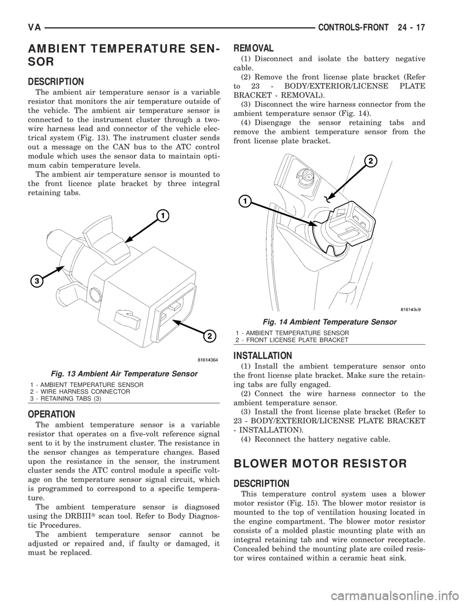
The ambient air temperature sensor is a variable
resistor that monitors the air temperature outside of
the vehicle. The ambient air temperature sensor is
connected to the instrument cluster through a two-
wire harness lead and connector of the vehicle elec-
trical system (Fig. 13). The instrument cluster sends
out a message on the CAN bus to the ATC control
module which uses the sensor data to maintain opti-
mum cabin temperature levels.
The ambient air temperature sensor is mounted to
the front licence plate bracket by three integral
retaining tabs.
OPERATION
The ambient temperature sensor is a variable
resistor that operates on a five-volt reference signal
sent to it by the instrument cluster. The resistance in
the sensor changes as temperature changes. Based
upon the resistance in the sensor, the instrument
cluster sends the ATC control module a specific volt-
age on the temperature sensor signal circuit, which
is programmed to correspond to a specific tempera-
ture.
The ambient temperature sensor is diagnosed
using the DRBIIItscan tool. Refer to Body Diagnos-
tic Procedures.
The ambient temperature sensor cannot be
adjusted or repaired and, if faulty or damaged, it
must be replaced.
REMOVAL
(1) Disconnect and isolate the battery negative
cable.
(2) Remove the front license plate bracket (Refer
to 23 - BODY/EXTERIOR/LICENSE PLATE
BRACKET - REMOVAL).
(3) Disconnect the wire harness connector from the
ambient temperature sensor (Fig. 14).
(4) Disengage the sensor retaining tabs and
remove the ambient temperature sensor from the
front license plate bracket.
INSTALLATION
(1) Install the ambient temperature sensor onto
the front license plate bracket. Make sure the retain-
ing tabs are fully engaged.
(2) Connect the wire harness connector to the
ambient temperature sensor.
(3) Install the front license plate bracket (Refer to
23 - BODY/EXTERIOR/LICENSE PLATE BRACKET
- INSTALLATION).
(4) Reconnect the battery negative cable.
BLOWER MOTOR RESISTOR
DESCRIPTION
This temperature control system uses a blower
motor resistor (Fig. 15). The blower motor resistor is
mounted to the top of ventilation housing located in
the engine compartment. The blower motor resistor
consists of a molded plastic mounting plate with an
integral retaining tab and wire connector receptacle.
Concealed behind the mounting plate are coiled resis-
tor wires contained within a ceramic heat sink.
Fig. 13 Ambient Air Temperature Sensor
1 - AMBIENT TEMPERATURE SENSOR
2 - WIRE HARNESS CONNECTOR
3 - RETAINING TABS (3)
Fig. 14 Ambient Temperature Sensor
1 - AMBIENT TEMPERATURE SENSOR
2 - FRONT LICENSE PLATE BRACKET
VACONTROLS-FRONT 24 - 17
Page 2056 of 2305
BLOWER MOTOR SWITCH
DESCRIPTION
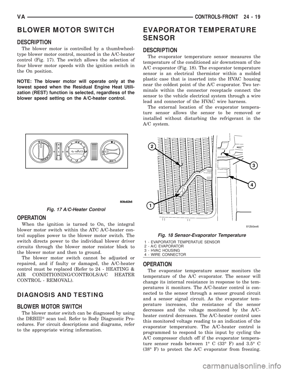
The blower motor is controlled by a thumbwheel-
type blower motor control, mounted in the A/C-heater
control (Fig. 17). The switch allows the selection of
four blower motor speeds with the ignition switch in
the On position.
NOTE: The blower motor will operate only at the
lowest speed when the Residual Engine Heat Utili-
zation (REST) function is selected, regardless of the
blower speed setting on the A/C-heater control.
OPERATION
When the ignition is turned to On, the integral
blower motor switch within the ATC A/C-heater con-
trol supplies power to the blower motor switch. The
switch directs power to the individual blower driver
circuits through the blower motor resistor block to
the blower motor and then to ground.
The blower motor switch cannot be adjusted or
repaired, and if faulty or damaged, the A/C-heater
control must be replaced (Refer to 24 - HEATING &
AIR CONDITIONING/CONTROLS/A/C HEATER
CONTROL - REMOVAL).
DIAGNOSIS AND TESTING
BLOWER MOTOR SWITCH
The blower motor switch can be diagnosed by using
the DRBIIItscan tool. Refer to Body Diagnostic Pro-
cedures. For circuit descriptions and diagrams, refer
to the appropriate wiring information.
EVAPORATOR TEMPERATURE
SENSOR
DESCRIPTION
The evaporator temperature sensor measures the
temperature of the conditioned air downstream of the
A/C evaporator (Fig. 18). The evaporator temperature
sensor is an electrical thermistor within a molded
plastic case that is inserted into the HVAC housing
near the coldest point of the A/C evaporator. Two ter-
minals within the connector receptacle connect the
sensor to the vehicle electrical system through a wire
lead and connector of the HVAC wire harness.
The external location of the evaporator tempera-
ture sensor allows the sensor to be removed or
installed without disturbing the refrigerant in the
A/C system.
OPERATION
The evaporator temperature sensor monitors the
temperature of the A/C evaporator. The sensor will
change its internal resistance in response to the tem-
peratures it monitors. The A/C-heater control is con-
nected to the sensor through a sensor ground circuit
and a sensor signal circuit. As the evaporator tem-
perature increases, the resistance of the sensor
decreases and the voltage monitored by the A/C-
heater control decreases. The A/C-heater control uses
this monitored voltage reading to an indication of the
evaporator temperature. The A/C-heater control is
programmed to respond to this input by cycling the
A/C compressor clutch off if the evaporator tempera-
ture sensor reads between 1É C (33É F) and 3.5É C
(38É F) to protect the A/C evaporator from freezing.
Fig. 17 A/C-Heater Control
Fig. 18 Sensor-Evaporator Temperature
1 - EVAPORATOR TEMPERATUE SENSOR
2 - A/C EVAPORATOR
3 - HVAC HOUSING
4 - WIRE CONNECTOR
VACONTROLS-FRONT 24 - 19
Page 2077 of 2305
INSTALLATION
(1) Install the rear A/C temperature control into
the accessory switch panel. Make sure the retaining
tabs are fully engaged.
(2) Connect the wire harness connector to the rear
A/C temperature control.
(3) Install the accessory switch panel (Refer to 23 -
BODY/INSTRUMENT PANEL/ACCESSORY
SWITCH BEZEL - INSTALLATION).
(4) Reconnect the negative battery cable.
TEMPERATURE SENSOR
DESCRIPTION
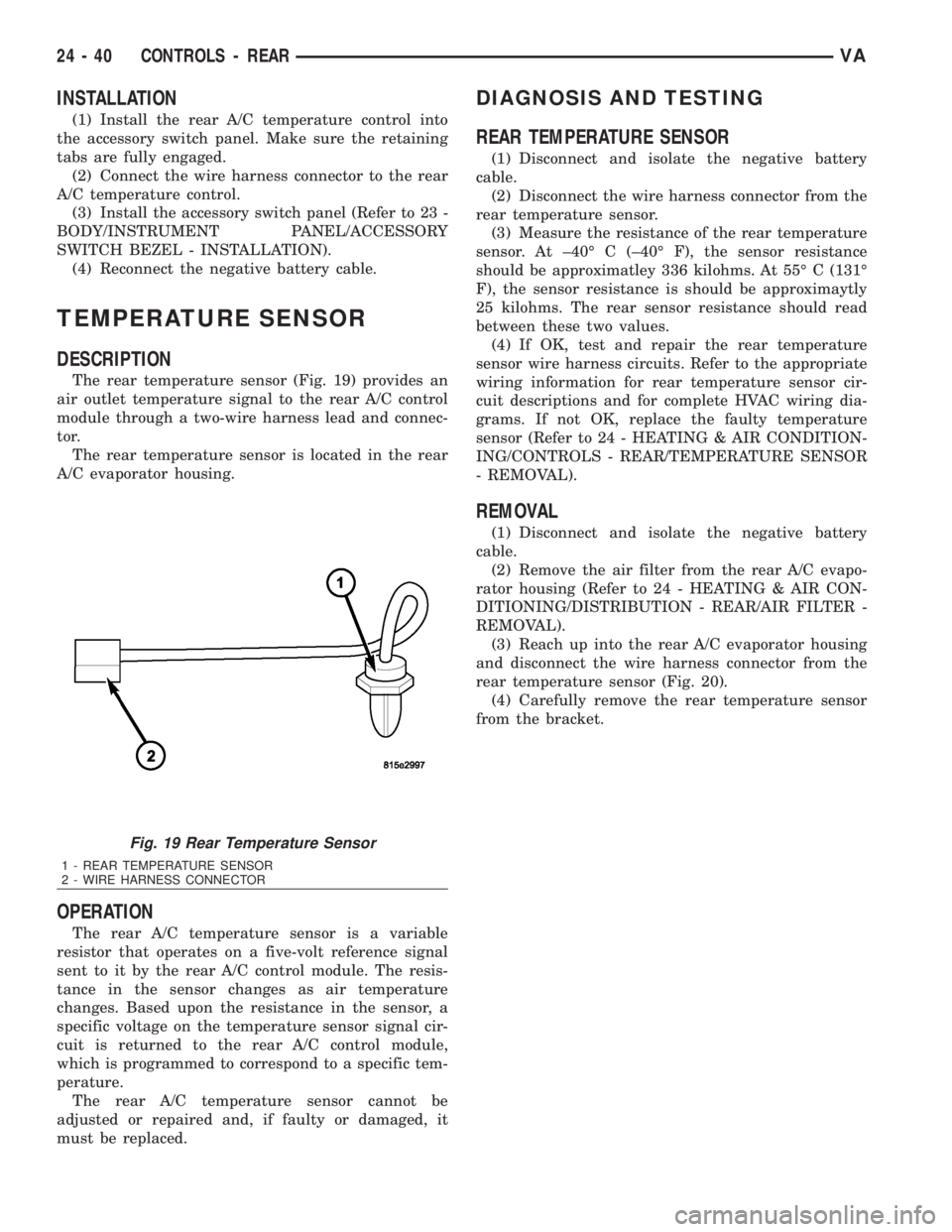
The rear temperature sensor (Fig. 19) provides an
air outlet temperature signal to the rear A/C control
module through a two-wire harness lead and connec-
tor.
The rear temperature sensor is located in the rear
A/C evaporator housing.
OPERATION
The rear A/C temperature sensor is a variable
resistor that operates on a five-volt reference signal
sent to it by the rear A/C control module. The resis-
tance in the sensor changes as air temperature
changes. Based upon the resistance in the sensor, a
specific voltage on the temperature sensor signal cir-
cuit is returned to the rear A/C control module,
which is programmed to correspond to a specific tem-
perature.
The rear A/C temperature sensor cannot be
adjusted or repaired and, if faulty or damaged, it
must be replaced.
DIAGNOSIS AND TESTING
REAR TEMPERATURE SENSOR
(1) Disconnect and isolate the negative battery
cable.
(2) Disconnect the wire harness connector from the
rear temperature sensor.
(3) Measure the resistance of the rear temperature
sensor. At ±40É C (±40É F), the sensor resistance
should be approximatley 336 kilohms. At 55É C (131É
F), the sensor resistance is should be approximaytly
25 kilohms. The rear sensor resistance should read
between these two values.
(4) If OK, test and repair the rear temperature
sensor wire harness circuits. Refer to the appropriate
wiring information for rear temperature sensor cir-
cuit descriptions and for complete HVAC wiring dia-
grams. If not OK, replace the faulty temperature
sensor (Refer to 24 - HEATING & AIR CONDITION-
ING/CONTROLS - REAR/TEMPERATURE SENSOR
- REMOVAL).
REMOVAL
(1) Disconnect and isolate the negative battery
cable.
(2) Remove the air filter from the rear A/C evapo-
rator housing (Refer to 24 - HEATING & AIR CON-
DITIONING/DISTRIBUTION - REAR/AIR FILTER -
REMOVAL).
(3) Reach up into the rear A/C evaporator housing
and disconnect the wire harness connector from the
rear temperature sensor (Fig. 20).
(4) Carefully remove the rear temperature sensor
from the bracket.
Fig. 19 Rear Temperature Sensor
1 - REAR TEMPERATURE SENSOR
2 - WIRE HARNESS CONNECTOR
24 - 40 CONTROLS - REARVA