2006 MERCEDES-BENZ SPRINTER ESP
[x] Cancel search: ESPPage 1418 of 2305
8W-80 CONNECTOR PIN-OUTS
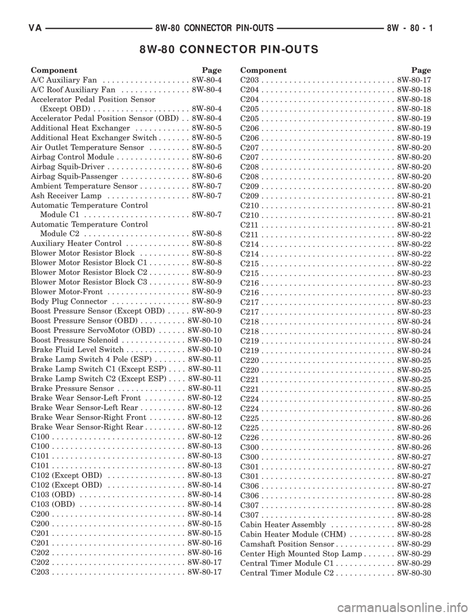
Component Page
A/C Auxiliary Fan................... 8W-80-4
A/C Roof Auxiliary Fan............... 8W-80-4
Accelerator Pedal Position Sensor
(Except OBD)..................... 8W-80-4
Accelerator Pedal Position Sensor (OBD) . . 8W-80-4
Additional Heat Exchanger............ 8W-80-5
Additional Heat Exchanger Switch....... 8W-80-5
Air Outlet Temperature Sensor......... 8W-80-5
Airbag Control Module................ 8W-80-6
Airbag Squib-Driver.................. 8W-80-6
Airbag Squib-Passenger............... 8W-80-6
Ambient Temperature Sensor........... 8W-80-7
Ash Receiver Lamp.................. 8W-80-7
Automatic Temperature Control
Module C1....................... 8W-80-7
Automatic Temperature Control
Module C2....................... 8W-80-8
Auxiliary Heater Control.............. 8W-80-8
Blower Motor Resistor Block........... 8W-80-8
Blower Motor Resistor Block C1......... 8W-80-8
Blower Motor Resistor Block C2......... 8W-80-9
Blower Motor Resistor Block C3......... 8W-80-9
Blower Motor-Front.................. 8W-80-9
Body Plug Connector................. 8W-80-9
Boost Pressure Sensor (Except OBD)..... 8W-80-9
Boost Pressure Sensor (OBD).......... 8W-80-10
Boost Pressure ServoMotor (OBD)...... 8W-80-10
Boost Pressure Solenoid.............. 8W-80-10
Brake Fluid Level Switch............. 8W-80-10
Brake Lamp Switch 4 Pole (ESP)....... 8W-80-11
Brake Lamp Switch C1 (Except ESP).... 8W-80-11
Brake Lamp Switch C2 (Except ESP).... 8W-80-11
Brake Pressure Sensor............... 8W-80-11
Brake Wear Sensor-Left Front......... 8W-80-12
Brake Wear Sensor-Left Rear.......... 8W-80-12
Brake Wear Sensor-Right Front........ 8W-80-12
Brake Wear Sensor-Right Rear......... 8W-80-12
C100............................. 8W-80-12
C100............................. 8W-80-13
C101............................. 8W-80-13
C101............................. 8W-80-13
C102 (Except OBD)................. 8W-80-13
C102 (Except OBD)................. 8W-80-14
C103 (OBD)....................... 8W-80-14
C103 (OBD)....................... 8W-80-14
C200............................. 8W-80-14
C200............................. 8W-80-15
C201............................. 8W-80-15
C201............................. 8W-80-16
C202............................. 8W-80-16
C202............................. 8W-80-17
C203............................. 8W-80-17Component Page
C203............................. 8W-80-17
C204............................. 8W-80-18
C204............................. 8W-80-18
C205............................. 8W-80-18
C205............................. 8W-80-19
C206............................. 8W-80-19
C206............................. 8W-80-19
C207............................. 8W-80-20
C207............................. 8W-80-20
C208............................. 8W-80-20
C208............................. 8W-80-20
C209............................. 8W-80-20
C209............................. 8W-80-21
C210............................. 8W-80-21
C210............................. 8W-80-21
C211 ............................. 8W-80-21
C211 ............................. 8W-80-22
C214............................. 8W-80-22
C214............................. 8W-80-22
C215............................. 8W-80-22
C215............................. 8W-80-23
C216............................. 8W-80-23
C216............................. 8W-80-23
C217............................. 8W-80-23
C217............................. 8W-80-23
C218............................. 8W-80-24
C218............................. 8W-80-24
C219............................. 8W-80-24
C219............................. 8W-80-24
C220............................. 8W-80-25
C220............................. 8W-80-25
C221............................. 8W-80-25
C221............................. 8W-80-25
C224............................. 8W-80-25
C224............................. 8W-80-26
C225............................. 8W-80-26
C225............................. 8W-80-26
C226............................. 8W-80-26
C300............................. 8W-80-26
C300............................. 8W-80-27
C301............................. 8W-80-27
C301............................. 8W-80-27
C306............................. 8W-80-27
C306............................. 8W-80-28
C307............................. 8W-80-28
C307............................. 8W-80-28
Cabin Heater Assembly.............. 8W-80-28
Cabin Heater Module (CHM).......... 8W-80-28
Camshaft Position Sensor............. 8W-80-29
Center High Mounted Stop Lamp....... 8W-80-29
Central Timer Module C1............. 8W-80-29
Central Timer Module C2............. 8W-80-30
VA8W-80 CONNECTOR PIN-OUTS 8W - 80 - 1
Page 1428 of 2305
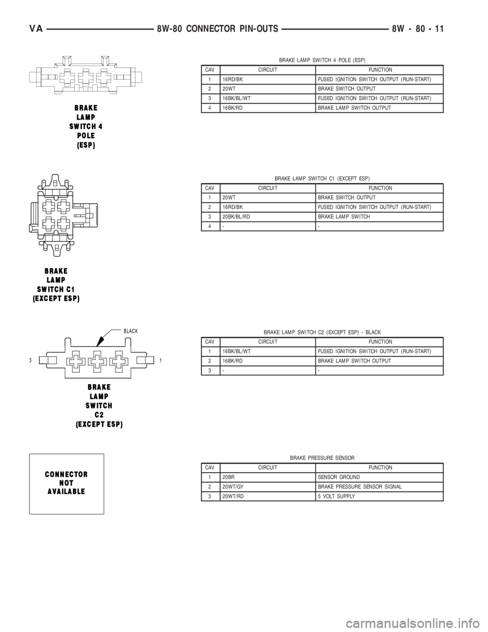
BRAKE LAMP SWITCH 4 POLE (ESP)
CAV CIRCUIT FUNCTION
1 16RD/BK FUSED IGNITION SWITCH OUTPUT (RUN-START)
2 20WT BRAKE SWITCH OUTPUT
3 16BK/BL/WT FUSED IGNITION SWITCH OUTPUT (RUN-START)
4 16BK/RD BRAKE LAMP SWITCH OUTPUT
BRAKE LAMP SWITCH C1 (EXCEPT ESP)
CAV CIRCUIT FUNCTION
1 20WT BRAKE SWITCH OUTPUT
2 16RD/BK FUSED IGNITION SWITCH OUTPUT (RUN-START)
3 20BK/BL/RD BRAKE LAMP SWITCH
4- -
BRAKE LAMP SWITCH C2 (EXCEPT ESP) - BLACK
CAV CIRCUIT FUNCTION
1 16BK/BL/WT FUSED IGNITION SWITCH OUTPUT (RUN-START)
2 16BK/RD BRAKE LAMP SWITCH OUTPUT
3- -
BRAKE PRESSURE SENSOR
CAV CIRCUIT FUNCTION
1 20BR SENSOR GROUND
2 20WT/GY BRAKE PRESSURE SENSOR SIGNAL
3 20WT/RD 5 VOLT SUPPLY
VA8W-80 CONNECTOR PIN-OUTS 8W - 80 - 11
Page 1663 of 2305
INSPECTION
Visually inspect the charge air cooler for cracks,
holes, or damage. Inspect the tubes, fins, and welds
for tears, breaks, or other damage. Replace the
charge air cooler if damage is found.
Pressure test the charge air cooler, using Charge
Air Cooler Tester Kit.
INSTALLATION
(1) Install charge air cooler to radiator (Fig. 3).
(2) Connect power steering cooler loop to charge
air cooler (Fig. 3).
(3) Connect charge air hoses (Fig. 3).
(4) Install both radiator trim pieces (Fig. 3).
(5) Install front grille with front cross member.
(6) Install headlamp assemblies.
(7) Install front bumper.
TURBOCHARGER
DESCRIPTION
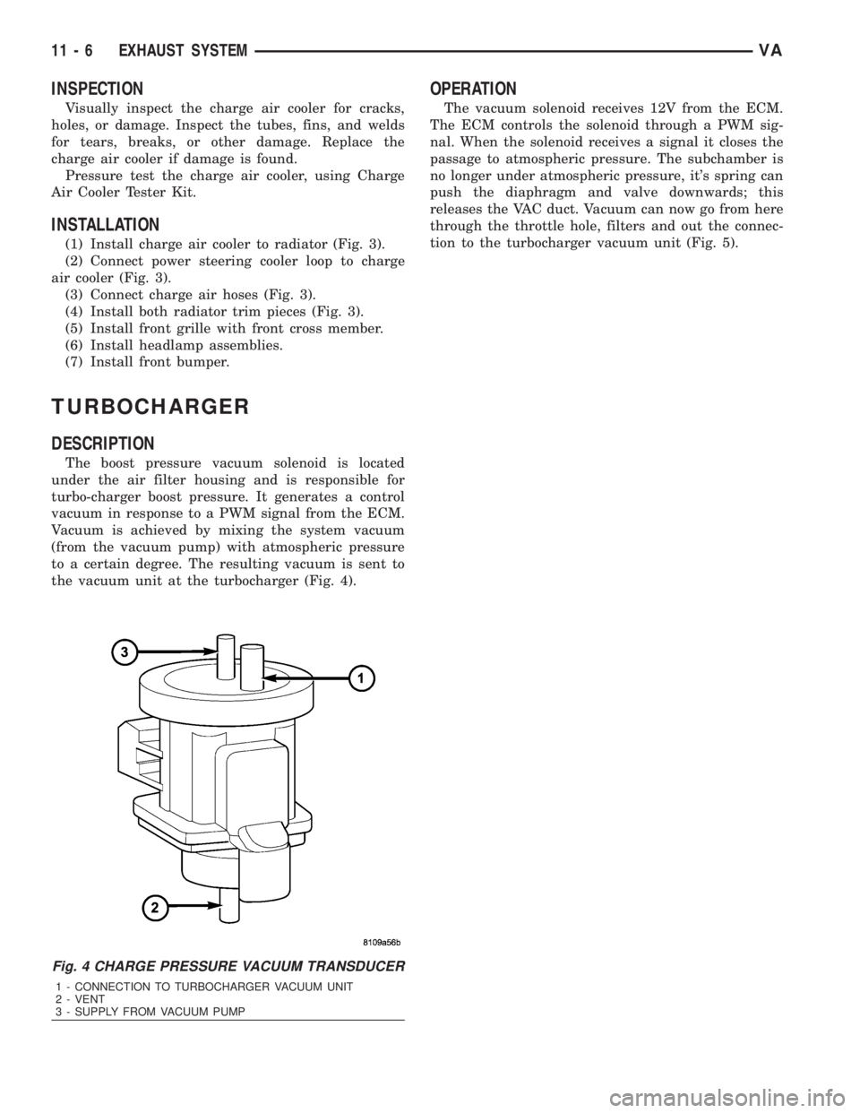
The boost pressure vacuum solenoid is located
under the air filter housing and is responsible for
turbo-charger boost pressure. It generates a control
vacuum in response to a PWM signal from the ECM.
Vacuum is achieved by mixing the system vacuum
(from the vacuum pump) with atmospheric pressure
to a certain degree. The resulting vacuum is sent to
the vacuum unit at the turbocharger (Fig. 4).
OPERATION
The vacuum solenoid receives 12V from the ECM.
The ECM controls the solenoid through a PWM sig-
nal. When the solenoid receives a signal it closes the
passage to atmospheric pressure. The subchamber is
no longer under atmospheric pressure, it's spring can
push the diaphragm and valve downwards; this
releases the VAC duct. Vacuum can now go from here
through the throttle hole, filters and out the connec-
tion to the turbocharger vacuum unit (Fig. 5).
Fig. 4 CHARGE PRESSURE VACUUM TRANSDUCER
1 - CONNECTION TO TURBOCHARGER VACUUM UNIT
2 - VENT
3 - SUPPLY FROM VACUUM PUMP
11 - 6 EXHAUST SYSTEMVA
Page 1684 of 2305
(7) Connect a scan tool, select from Main Menu,
System Select, Engine, System Tests, Fuel Quantity
Test, Engine Cranking Test and follow the screen.
(8) After ten seconds, a maximum of 2.5 ml
(between2&3graduation lines) may be reached in
the inner vials. If the level has exceeded the 2.5 ml,
replace that affected cylinder's injector, clear the
memory using the scan tool, empty the test vials, and
retest.
RUNNING TEST
NOTE: If an injector is found to be out of specifica-
tion, repeat this test procedure after the injector
replacement. Hydraulic flow will take the path of
least resistance and multiple failures may be identi-
fied. Engine temperature must be above 80É C
(176ÉF) to perform the running test.
Perform this test with the engine at operating tem-
perature. This test will assist in determining a defec-
tive or internally leaking injector(s) is present by
measuring the amount of fuel return.
(1) Turn the ignition off.
(2) Remove the engine cover (Refer to 9 - ENGINE
- REMOVAL).
(3) Disconnect the fuel return hoses at the top of
the injectors.
(4) Pinch off the fuel return line at the banjo bolt
fitting of the fuel rail.
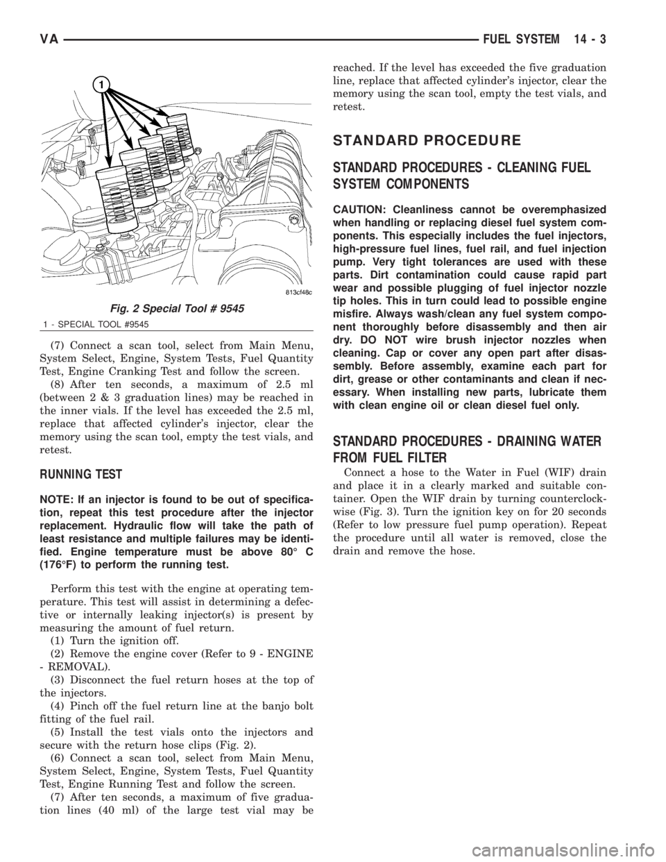
(5) Install the test vials onto the injectors and
secure with the return hose clips (Fig. 2).
(6) Connect a scan tool, select from Main Menu,
System Select, Engine, System Tests, Fuel Quantity
Test, Engine Running Test and follow the screen.
(7) After ten seconds, a maximum of five gradua-
tion lines (40 ml) of the large test vial may bereached. If the level has exceeded the five graduation
line, replace that affected cylinder's injector, clear the
memory using the scan tool, empty the test vials, and
retest.
STANDARD PROCEDURE
STANDARD PROCEDURES - CLEANING FUEL
SYSTEM COMPONENTS
CAUTION: Cleanliness cannot be overemphasized
when handling or replacing diesel fuel system com-
ponents. This especially includes the fuel injectors,
high-pressure fuel lines, fuel rail, and fuel injection
pump. Very tight tolerances are used with these
parts. Dirt contamination could cause rapid part
wear and possible plugging of fuel injector nozzle
tip holes. This in turn could lead to possible engine
misfire. Always wash/clean any fuel system compo-
nent thoroughly before disassembly and then air
dry. DO NOT wire brush injector nozzles when
cleaning. Cap or cover any open part after disas-
sembly. Before assembly, examine each part for
dirt, grease or other contaminants and clean if nec-
essary. When installing new parts, lubricate them
with clean engine oil or clean diesel fuel only.
STANDARD PROCEDURES - DRAINING WATER
FROM FUEL FILTER
Connect a hose to the Water in Fuel (WIF) drain
and place it in a clearly marked and suitable con-
tainer. Open the WIF drain by turning counterclock-
wise (Fig. 3). Turn the ignition key on for 20 seconds
(Refer to low pressure fuel pump operation). Repeat
the procedure until all water is removed, close the
drain and remove the hose.
Fig. 2 Special Tool # 9545
1 - SPECIAL TOOL #9545
VAFUEL SYSTEM 14 - 3
Page 1690 of 2305
(4) Fill fuel tank with fresh diesel fuel.
(5) Drain and remove the fuel filter. (Refer to 14 -
FUEL SYSTEM/FUEL DELIVERY/FUEL FILTER /
WATER SEPARATOR - REMOVAL)
(6) Install a new fuel filter. (Refer to 14 - FUEL
SYSTEM/FUEL DELIVERY/FUEL FILTER / WATER
SEPARATOR - INSTALLATION)
(7) Check the engine control module for any diag-
nostic trouble codes (DTCs). Record and clear any
DTCs that are present.
(8) Start and run the engine. Run the engine for
up to 15 minutes to allow time for any DTCs to reset
and shut off the engine.
(9) Check the engine control module for any diag-
nostic trouble codes (DTCs). Record any DTCs that
are present. Refer to the appropriate engine electrical
diagnostics to diagnose any DTCs that were set.
CAUTION: With the high pressure fuel system in
this vehicle, any residual contaminated fuel will be
removed very quickly. Shut off the engine immedi-
ately if signs of engine damage are noted.The engine should then be evaluated to determine
if the contaminated fuel has caused any damage to
the fuel system and/or engine. Indicators that the
fuel system has been damaged include the following:
²Unstable fuel rail pressure. This can manifest
itself as instability of idle speeds, excessive under-
shoot/overshoot at engine start-up, or excessive
undershoot/overshoot when the engine operating con-
ditions change. A typical engine response to a large
rail pressure undershoot would be a decrease in
engine speed or engine stall.
²Excessive noise from the engine. This could indi-
cate poor rail pressure control or the inability of the
injection system to inject the proper amount of fuel.
²Excessive smoke (black or white). This could
indicate the inability of the fuel system to inject the
proper amount of fuel.
NOTE: If any of these conditions are exhibited after
cleaning the fuel system, proceed to the appropri-
ate engine electrical diagnostic information. Repair
the fuel system and/or engine as necessary.
SPECIFICATIONS
TORQUE
DESCRIPTION N´m Ft. Lbs. In. Lbs.
FUEL TANK MOUNTING NUTS 15 - 17 11 - 13 -
FUEL TANK MODULE LOCKRING (LOCK-
NUT)60 44 -
PRESSURE CONTROL VALVE NUT TO
FUEL RAIL (2 STAGES)60, loosen 90É, re-
tighten to 8044, loosen 90É, re-
tighten to 59-
SPECIAL TOOLS
FUEL SYSTEM
SPECIAL TOOL CROSS REFERENCE CHART
MB
TOOL #MILLER
TOOL #DESCRIPTION
N/A 5069-2 FUEL GAUGE
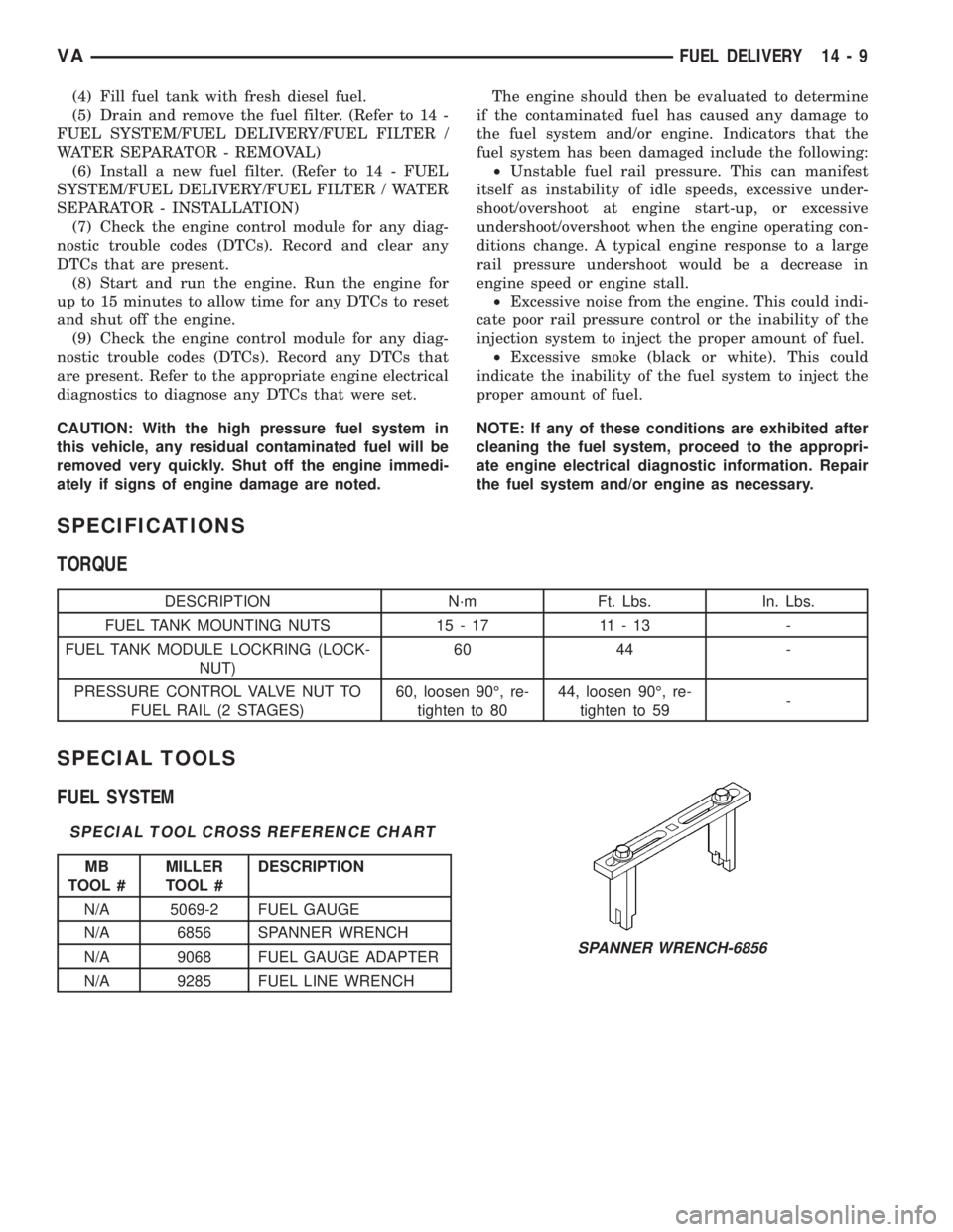
N/A 6856 SPANNER WRENCH
N/A 9068 FUEL GAUGE ADAPTER
N/A 9285 FUEL LINE WRENCH
SPANNER WRENCH-6856
VAFUEL DELIVERY 14 - 9
Page 1715 of 2305
is synchronized by means of the camshaft signal and
the crankshaft signal.
OPERATION
On the camshaft sensor's signal line, a high signal
correspons to a voltage of 0-5V. If the segment
machined into the exhaust camshaft sprocket is posi-
tioned opposite the camshaft sensor, the camshaft
signal is low, approximately 0V. This signal is used
by the engine control module (ECM) for detecting
ignition TDC of cylinder 1 as the engine rotates. If no
signal is supplied by the camshaft position sensor,
the vehicle will not start because cylinder order can
not be detected.
REMOVAL
(1) Disconnect negative battery cable.
(2) Remove engine cover
(3) Disconnect camshaft position sensor electrical
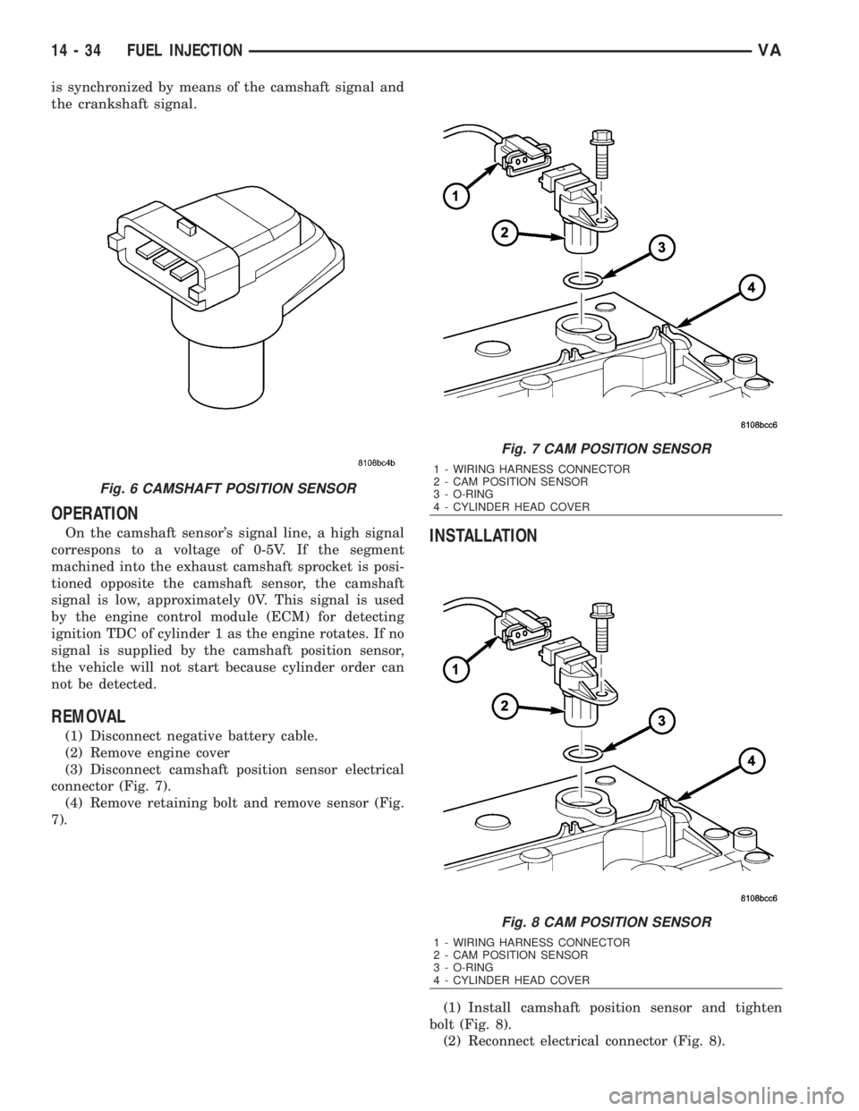
connector (Fig. 7).
(4) Remove retaining bolt and remove sensor (Fig.
7).
INSTALLATION
(1) Install camshaft position sensor and tighten
bolt (Fig. 8).
(2) Reconnect electrical connector (Fig. 8).
Fig. 6 CAMSHAFT POSITION SENSOR
Fig. 7 CAM POSITION SENSOR
1 - WIRING HARNESS CONNECTOR
2 - CAM POSITION SENSOR
3 - O-RING
4 - CYLINDER HEAD COVER
Fig. 8 CAM POSITION SENSOR
1 - WIRING HARNESS CONNECTOR
2 - CAM POSITION SENSOR
3 - O-RING
4 - CYLINDER HEAD COVER
14 - 34 FUEL INJECTIONVA
Page 1718 of 2305
position against the opening forces applied to its
pressure stage (Fig. 11).
Injector opens (start of injection)
The solenoid valve is energized with the pickup
current which serves to ensure that it open quickly.
The force exerted by the triggered solenoid now
exceeds that of the valve spring and the armature
opens the bleed orifice. Almost immediately, the high-
level pick-up current is reduced to the lower holding
current required for the electromagnet. This is possi-
ble due to the magnetic circuit's air gap now being
smaller. When the bleed orifice opens, fuel can flow
from the valve control chamber into the cavity situ-
ated above it, and from there via the fuel return to
the tank. The bleed orifice prevents complete pres-
sure balance, and the pressure in the valve control
chamber sinks as a result. This leads to the pressure
in the valve-control chamber being lower than that in
the nozzle's chamber volume which is still at the
same pressure level as the rail. The reduced pressure
in the valve-control chamber causes a reduction in
the force exerted on the control plunger, the nozzle
needle open as a result, and injection starts (Fig. 11).
Injector opens fully
The control plunger reaches its upper stop where it
remains supported by a cushion of fuel which is gen-
erated by the flow of fuel between the bleed and feed
orifices. The injector nozzle has now opened fully,
and the fuel is injected into the combustion chamber
at a pressure almost equal to that in the fuel rail
(Fig. 11).
Injector closes (end of injection)
As soon as the solenoid valve is no longer trig-
gered, the valve spring forces the armature down-
wards and the ball closes the bleed orifice. The
armature is a 2±piece design. Here, although the
armature plate is guided by a driver shoulder in its
downward movement, it can ªoverspringº with the
return spring so that it exerts no downwards-acting
forces on the armature and the ball. The closing of
the bleed orifice lead to pressure build up in the con-
trol chamber via the input from the feed orifice. This
pressure is the same as that in the rail and exerts an
increased force on the control plunger through its
end face. This force, together with that of the spring,
now exceeds the force exerted by the chamber volume
and the nozzle needle closes. Injection ceases as soon
as the nozzle needle comes up against its bottom stop
again (Fig. 11).
STANDARD PROCEDURE
STANDARD PROCEDURE - INJECTOR CLASSI-
FICATION
NOTE: Fuel Injectors have different flow rates.
When ALL injectors are removed, re-enter all injec-
tor six digit codes.
The classification of injectors into 3 classes
describes the quantity characteristic of the injector.
This will make it possible in the future to match the
engine software to the tolerances of the injector
within a more narrowly graduated range. Classifica-
tion can be clearly recognized, and assigned only by
means of a DRBIIIt.
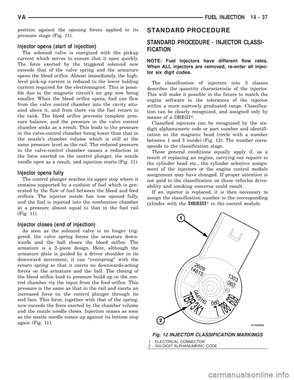
Classified injectors can be recognized by the six-
digit alphanumeric code or part number and identifi-
cation on the magnetic head (circle with a number
between 1 and 3 inside) (Fig. 12). The number corre-
sponds to the classification stage.
These general conditions equally apply if, as a
result of replacing an engine, carrying out repairs to
the cylinder head etc., the cylinder selective assign-
ment of the injectors or the engine control module
assignment may have changed. If proper attention is
not paid to the classification on these vehicles drive-
ability and smoking concerns could result.
If an injector is replaced, it is then necessary to
assign the classification number to the corresponding
cylinder with theDRBIIItin the control module.
Fig. 12 INJECTOR CLASSIFICATION MARKINGS
1 - ELECTRICAL CONNECTOR
2 - SIX-DIGIT ALPHANUMERIC CODE
VAFUEL INJECTION 14 - 37
Page 1721 of 2305
INSTALLATION
(1) (Refer to 14 - FUEL SYSTEM/FUEL INJEC-
TION - WARNING) Install the sealing ring on to the
sensor (Fig. 14).
(2) Screw the sensor in to the fuel rail. Counter-
hold the threaded connection and tighten the sensor
to 18 lbs. ft. (25 N´m.) (Fig. 14).
(3) Connect the wiring harness to the sensor.
(4) Install the mixing housing.
CAUTION: Care must be taken when installing the
engine cover. Assure the proper routing of the fuel
injector return fuel hose to the banjo bolt fitting in
the left rear corner of the cover. Failure to do so
may pinch or damage the hose causing fuel leakage
or a driveability concern.
(5) Connect negative battery cable.
FUEL PRESSURE SOLENOID
DESCRIPTION
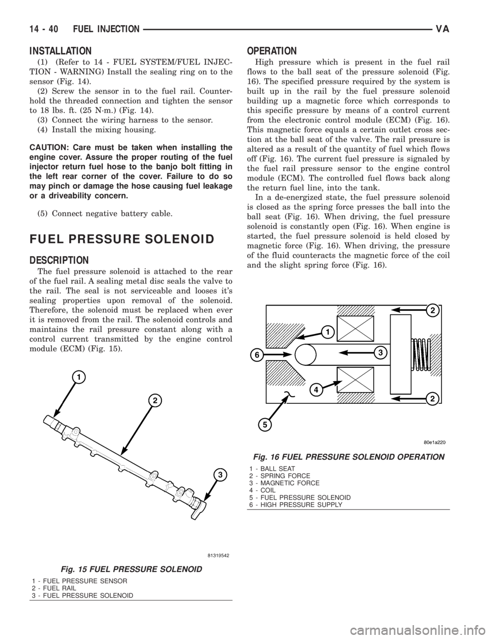
The fuel pressure solenoid is attached to the rear
of the fuel rail. A sealing metal disc seals the valve to
the rail. The seal is not serviceable and looses it's
sealing properties upon removal of the solenoid.
Therefore, the solenoid must be replaced when ever
it is removed from the rail. The solenoid controls and
maintains the rail pressure constant along with a
control current transmitted by the engine control
module (ECM) (Fig. 15).
OPERATION
High pressure which is present in the fuel rail
flows to the ball seat of the pressure solenoid (Fig.
16). The specified pressure required by the system is
built up in the rail by the fuel pressure solenoid
building up a magnetic force which corresponds to
this specific pressure by means of a control current
from the electronic control module (ECM) (Fig. 16).
This magnetic force equals a certain outlet cross sec-
tion at the ball seat of the valve. The rail pressure is
altered as a result of the quantity of fuel which flows
off (Fig. 16). The current fuel pressure is signaled by
the fuel rail pressure sensor to the engine control
module (ECM). The controlled fuel flows back along
the return fuel line, into the tank.
In a de-energized state, the fuel pressure solenoid
is closed as the spring force presses the ball into the
ball seat (Fig. 16). When driving, the fuel pressure
solenoid is constantly open (Fig. 16). When engine is
started, the fuel pressure solenoid is held closed by
magnetic force (Fig. 16). When driving, the pressure
of the fluid counteracts the magnetic force of the coil
and the slight spring force (Fig. 16).
Fig. 15 FUEL PRESSURE SOLENOID
1 - FUEL PRESSURE SENSOR
2 - FUEL RAIL
3 - FUEL PRESSURE SOLENOID
Fig. 16 FUEL PRESSURE SOLENOID OPERATION
1 - BALL SEAT
2 - SPRING FORCE
3 - MAGNETIC FORCE
4 - COIL
5 - FUEL PRESSURE SOLENOID
6 - HIGH PRESSURE SUPPLY
14 - 40 FUEL INJECTIONVA