2006 MERCEDES-BENZ SPRINTER ESP
[x] Cancel search: ESPPage 708 of 2305

FASTENER IDENTIFICATION
DESCRIPTION
The SAE bolt strength grades range from grade 2
to grade 8. The higher the grade number, the greater
the bolt strength. Identification is determined by the
line marks on the top of each bolt head. The actual
bolt strength grade corresponds to the number of line
marks plus 2. The most commonly used metric bolt
strength classes are 9.8 and 10.9. The metric
strength class identification number is imprinted on
the head of the bolt. The higher the class number,
the greater the bolt strength. Some metric nuts are
imprinted with a single-digit strength class on the
nut face. Refer to the Fastener Identification and
Fastener Strength Charts (Fig. 2) and (Fig. 3).
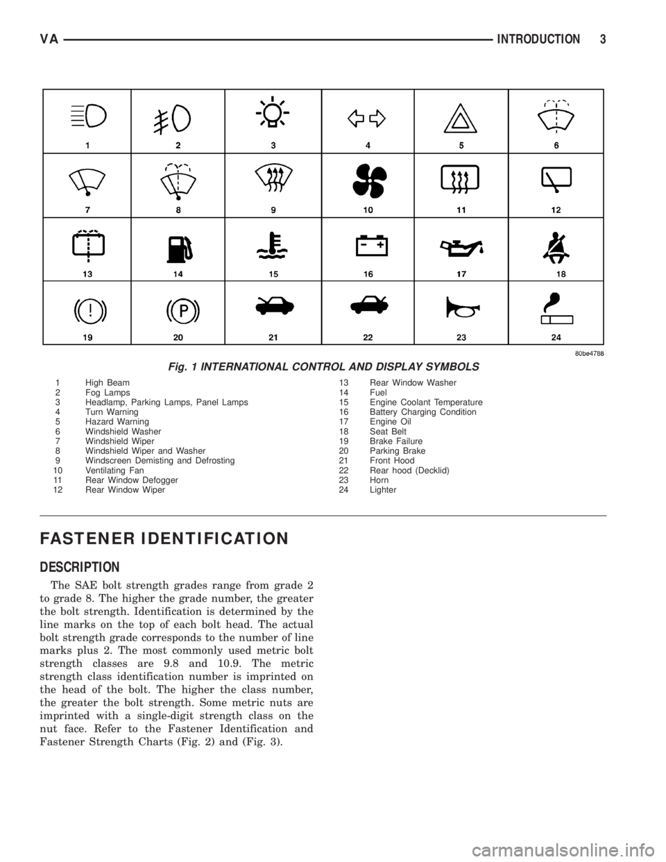
Fig. 1 INTERNATIONAL CONTROL AND DISPLAY SYMBOLS
1 High Beam 13 Rear Window Washer
2 Fog Lamps 14 Fuel
3 Headlamp, Parking Lamps, Panel Lamps 15 Engine Coolant Temperature
4 Turn Warning 16 Battery Charging Condition
5 Hazard Warning 17 Engine Oil
6 Windshield Washer 18 Seat Belt
7 Windshield Wiper 19 Brake Failure
8 Windshield Wiper and Washer 20 Parking Brake
9 Windscreen Demisting and Defrosting 21 Front Hood
10 Ventilating Fan 22 Rear hood (Decklid)
11 Rear Window Defogger 23 Horn
12 Rear Window Wiper 24 Lighter
VAINTRODUCTION 3
Page 722 of 2305

(6) Start the engine in the vehicle which has the
booster battery, let the engine idle a few minutes,
then start the engine in the vehicle with the dis-
charged battery.
CAUTION: Do not crank starter motor on disabled
vehicle for more than 15 seconds, starter will over-
heat and could fail.
(7) Allow battery in disabled vehicle to charge to
at least 12.4 volts (75% charge) before attempting to
start engine. If engine does not start within 15 sec-
onds, stop cranking engine and allow starter to cool
(15 min.), before cranking again.
DISCONNECT CABLE CLAMPS AS FOLLOWS:
²Disconnect BLACK cable clamp from engine
ground on disabled vehicle.
²When using a Booster vehicle, disconnect
BLACK cable clamp from battery negative terminal.
Disconnect RED cable clamp from battery positive
terminal.
²Disconnect RED cable clamp from battery posi-
tive terminal on disabled vehicle.
TOWING
STANDARD PROCEDURE - TOWING
WARNING: Do not tow the vehicle if the key cannot
be turned in the ignition lock. If the key cannot be
turned, the ignition lock remains locked and the
vehicle cannot be steered. With the engine not run-
ning there is no power assistance for the braking
and steering systems. In this case, it is important to
keep in mind that a considerably higher degree of
effort is necessary to brake and steer the vehicle.
The vehicle must not be towed with the front axle
raised and the key in position 2 in the ignition lock
as the drive wheels could then lock due to the
acceleration skid control (ASR)
If the Engine is Damaged
For towing distances up to 30 miles (about 50
km)
²Shift selector lever in ªNº position.
²Do not exceed a towing speed of 30 m.p.h. (50
km/h).
For towing distances greater than 30 mile
(about 50 km)
²Remove the propeller shafts leading to the drive
axles. The vehicle can be towed without restriction.
If the Transmission is Damaged
²Remove the propeller shafts leading to the drive
axles. The vehicle can be towed without restriction.
If the Front Axle is Damaged
²Raise the front axle.
²Observe the same towing restrictions as for
engine damage.
If the Rear Axle is Damaged
²Raise the rear axle.
NOTE: Comply with local legal regulations regard-
ing towing vehicles.
SAFETY PRECAUTIONS
NOTE: The following safety precautions must be
observed when towing a vehicle.
²Secure loose and protruding parts.
²Always use a safety chain system that is inde-
pendent of the lifting and towing equipment.
²Do not allow towing equipment to contact the
disabled vehicle's fuel tank.
²Do not allow anyone under the disabled vehicle
while it is lifted by the towing device.
²Do not allow passengers to ride in a vehicle
being towed.
²Always observe state and local laws regarding
towing regulations.
²Do not tow a vehicle in a manner that could
jeopardize the safety of the operator, pedestrians or
other motorists.
²Do not attach tow chains, T-hooks, J-hooks, or a
tow sling to a bumper, steering linkage, drive shafts
or a non-reinforced frame hole.
²Remove exhaust pipe tips that interfere with the
tow sling and crossbar
²Padding should be placed between the tow sling/
crossbar and any painted surfaces
²When placing tow hooks on the rear axle, posi-
tion them so they do not damage the brake tubing or
hoses
²Do not tow the vehicle by connecting to the front
or rear shock absorbers
²Do not tow a heavily loaded vehicle. Damage to
the vehicle may result. Use a flatbed device to trans-
port a loaded vehicle.
GROUND CLEARANCE
CAUTION: If vehicle is towed with wheels removed,
install lug nuts to retain brake drums.
A towed vehicle should be raised until lifted wheels
are a minimum 100 mm (4 in) from the ground. Be
sure there is adequate ground clearance at the oppo-
site end of the vehicle, especially when towing over
rough terrain, steep rises in the road or if the vehicle
is equipped with air dams, spoilers, and/or ground
VALUBRICATION & MAINTENANCE 0 - 7
Page 791 of 2305

POWER BRAKE BOOSTER
DESCRIPTION.........................19
OPERATION...........................19
REMOVAL.............................20
INSTALLATION.........................20
ROTORS
REMOVAL
REMOVAL - FRONT (SRW)..............20
REMOVAL - REAR (SRW)...............20
REMOVAL - FRONT (DRW)..............21
REMOVAL - REAR (DRW)...............21
INSTALLATION
INSTALLATION - FRONT (SRW)..........22
INSTALLATION - REAR (SRW)...........22
INSTALLATION - FRONT (DRW)..........22
INSTALLATION - REAR (DRW)...........22
SUPPORT PLATE
REMOVAL - REAR......................23
INSTALLATION - REAR...................23
PARKING BRAKE
SPECIFICATIONS
TORQUE CHART......................23
SPECIAL TOOLS
PARK BRAKE........................24
CABLE TENSIONER
REMOVAL.............................24INSTALLATION.........................24
CABLES
REMOVAL
REMOVAL - FRONT....................24
REMOVAL - REAR.....................25
INSTALLATION
INSTALLATION - FRONT................25
INSTALLATION - REAR.................26
ADJUSTMENTS
ADJUSTMENT - PARKING BRAKE CABLES . 26
LEVER
REMOVAL.............................26
INSTALLATION.........................27
SHOES
REMOVAL
REMOVAL - (SRW)....................27
REMOVAL - (DRW)....................27
CLEANING - REAR DRUM IN HAT BRAKE....28
INSTALLATION
INSTALLATION - (SRW).................28
INSTALLATION - (DRW).................28
ADJUSTMENTS
ADJUSTMENT........................28
BRAKES - BASE
DIAGNOSIS AND TESTING - BASE BRAKE SYS-
TEM
Base brake components consist of the brake pads,
calipers, brake drum in hat rotor in the rear, rotors,
brake lines, master cylinder, booster, and parking
brake components.
Brake diagnosis involves determining if the prob-
lem is related to a mechanical, hydraulic, or vacuum
operated component.
The first diagnosis step is the preliminary check.
PRELIMINARY BRAKE CHECK
(1) Check condition of tires and wheels. Damaged
wheels and worn, damaged, or underinflated tires
can cause pull, shudder, vibration, and a condition
similar to grab.
(2) If complaint was based on noise when braking,
check suspension components. Jounce front and rear
of vehicle and listen for noise that might be caused
by loose, worn or damaged suspension or steering
components.
(3) Inspect brake fluid level and condition. Note
that the brake reservoir fluid level will decrease in
proportion to normal lining wear.Also note that
brake fluid tends to darken over time. This is
normal and should not be mistaken for contam-
ination.(a) If fluid level is abnormally low, look for evi-
dence of leaks at calipers, wheel cylinders, brake
lines, and master cylinder.
(b) If fluid appears contaminated, drain out a
sample to examine. System will have to be flushed
if fluid is separated into layers, or contains a sub-
stance other than brake fluid. The system seals
and cups will also have to be replaced after flush-
ing. Use clean brake fluid to flush the system.
(4) Check parking brake operation. Verify free
movement and full release of cables and pedal. Also
note if vehicle was being operated with parking
brake partially applied.
(5) Check brake pedal operation. Verify that pedal
does not bind and has adequate free play. If pedal
lacks free play, check pedal and power booster for
being loose or for bind condition. Do not road test
until condition is corrected.
(6) Check booster vacuum check valve and hose.
(7) If components checked appear OK, road test
the vehicle.
ROAD TESTING
(1) If complaint involved low brake pedal, pump
pedal and note if it comes back up to normal height.
(2) Check brake pedal response with transmission
in Neutral and engine running. Pedal should remain
firm under constant foot pressure.
5 - 2 BRAKES - BASEVA
Page 805 of 2305

(3) Check the brake system for any leaks.
(4) Reconnect the electrical connector to the brake
fluid level indicator (Fig. 14).
ALB LEVER
REMOVAL
(1) Raise and support the vehicle.
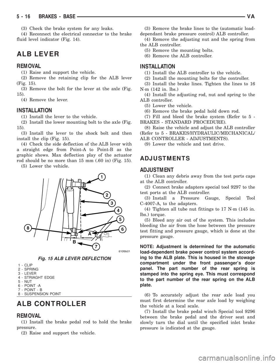
(2) Remove the retaining clip for the ALB lever
(Fig. 15).
(3) Remove the bolt for the lever at the axle (Fig.
15).
(4) Remove the lever.
INSTALLATION
(1) Install the lever to the vehicle.
(2) Install the lower mounting bolt to the axle (Fig.
15).
(3) Install the lever to the shock bolt and then
install the clip (Fig. 15).
(4) Check the side deflection of the ALB lever with
a straight edge from Point-A to Point-B as the
graphic shows. Max deflection play of the actuator
rod should be no more than 15 mm (.60 in) (Fig. 15).
(5) Lower the vehicle.
ALB CONTROLLER
REMOVAL
(1) Install the brake pedal rod to hold the brake
pressure.
(2) Raise and support the vehicle.(3) Remove the brake lines to the (automatic load-
dependant brake pressure control) ALB controller.
(4) Remove the adjusting nut and the spring from
the ALB controller.
(5) Remove the mounting bolts.
(6) Remove the ALB controller.
INSTALLATION
(1) Install the ALB controller to the vehicle.
(2) Install the mounting bolts for the controller.
(3) Install the brake lines. Tighten the lines to 16
N´m (142 in. lbs.)
(4) Install the adjusting rod, nut and spring to the
ALB controller.
(5) Lower the vehicle.
(6) Remove the brake pedal hold down rod.
(7) Fill and bleed the brake system (Refer to 5 -
BRAKES - STANDARD PROCEDURE).
(8) Raise the vehicle and adjust the ALB controller
(Refer to 5 - BRAKES/HYDRAULIC/MECHANICAL/
ALB CONTROLLER - ADJUSTMENTS).
(9) Lower the vehicle and test drive.
ADJUSTMENTS
ADJUSTMENT
(1) Clean any debris away from the test ports caps
at the ALB controller.
(2) Connect brake adapters special tool 9297 to the
test ports at the ALB controller.
(3) Install a Pressure Gauge, Special Tool
C-4007-A, to the adapters.
(4) Tighten all tube nut fittings to 17 N´m (145 in.
lbs.) torque.
(5) Bleed any air out of the system. This includes
bleeding the air from the hose between the pressure
test fitting and pressure gauge, which is done at the
pressure gauge.
NOTE: Adjustment is determined for the automatic
load-dependent brake power control system accord-
ing to the ALB plate. This is housed in the stowage
compartment under the front passenger's door
panel. The part number of the rear spring is
stamped into the spring eye. This must correspond
to the part number of the rear spring on the ALB
plate.
(6) To accurately adjust the rear axle load you
must first determine the rear axle load by weighing
the vehicle at a local scale.
(7) Install the brake pedal winch Special tool 9296
between the brake pedal and the driver seat and
slowly turn the dial until the specified inlet brake
pressure is indicated at the gauge.
Fig. 15 ALB LEVER DEFLECTION
1 - CLIP
2 - SPRING
3 - LEVER
4 - STRIAGHT EDGE
5 - NUT
6 - POINT -A
7 - POINT - B
8 - SUSPENSION POINT
5 - 16 BRAKES - BASEVA
Page 822 of 2305

The Steering Angle Sensor is used to measure rate/
speed and direction of the steering wheel. This sen-
sor has 4 wires 12V, ground and 2 CAN Bus circuits.
This sensor is wired directly to the CAN Bus. This
sensor has to be programmed using the DRB IIIt
(Fig. 5).
REMOVAL
(1) Disconnect the battery.
(2) Remove the airbag (Refer to 8 - ELECTRICAL/
RESTRAINTS/AIRBAG CONTROL MODULE -
REMOVAL).
(3) Remove the steering wheel (Refer to 19 -
STEERING/COLUMN/STEERING WHEEL -
REMOVAL).
(4) Remove the front cover (Fig. 6).
(5) Remove the upper and lower steering column
covers (Fig. 6).
(6) Remove the clockspring (Refer to 8 - ELECTRI-
CAL/RESTRAINTS/CLOCKSPRING - REMOVAL)
(Fig. 6).
(7) Disconnect the electrical connector from the
steering angle sensor (Fig. 6).
(8) Remove the steering angle sensor (Fig. 6).
INSTALLATION
NOTE: The installation position of the steering
angle sensor must have the plug connection at the
bottom (Fig. 6).
(1) Install the steering angle sensor to the column
(Fig. 6).(2) Reconnect the electrical connector to the steer-
ing angle sensor (Fig. 6).
(3) Install the clockspring (Refer to 8 - ELECTRI-
CAL/RESTRAINTS/CLOCKSPRING - INSTALLA-
TION) (Fig. 6).
(4) Install the upper and lower steering column
covers (Fig. 6).
(5) Install the front cover (Fig. 6).
(6) Install the steering wheel (Refer to 19 -
STEERING/COLUMN/STEERING WHEEL -
INSTALLATION).
(7) Install the airbag (Refer to 8 - ELECTRICAL/
RESTRAINTS/AIRBAG CONTROL MODULE -
INSTALLATION).
(8) Reconnect the battery.
(9) Recalibrate the steering angle sensor using the
scan tool.
LATERAL ACCELERATION
SENSOR
DESCRIPTION
The Yaw Rate and Lateral Acceleration Sensor is
housed into one unit (Fig. 7)(each individual sen-
sor can not be replaced separately the whole
housing unit must be replaced when servicing).
The sensor is used to measure side to side (Lateral)
motion and vehicle rotational sensing (how fast the
vehicle is turning). This is a 6±wire sensor with all
six wires connected to the ESP/ABS module.
REMOVAL
(1) Disconnect the battery.
(2) Move the drivers seat forward and upwards.
Fig. 6 STEERING ANGLE SENSOR
1 - UPPER STEERING COLUMN COVER
2 - CLOCKSPRING
3 - STEERING ANGLE SENSOR
4 - LOWER STEERING COLUMN COVER
5 - FRONT COVER
6 - STEERING ANGLE SENSOR ELECTRICAL CONNECTION
Fig. 7 YAW/LATERAL ACCELERATION SENSOR
1 - SEAT BOX
2 - YAW RATE/ LATERAL ACCELERATION SENSOR
VABRAKES - ABS 5 - 33
Page 824 of 2305

(5) Install the bracket with the control modules
(Fig. 9).
(6) Install the cover for the drivers seat (Fig. 8).
(7) Return the drivers seat to normal position.
(8) Reconnect the battery.
(9) Perform diagnosis quick check and road test
the vehicle.
YAW RATE SENSOR
DESCRIPTION
The Yaw Rate and Lateral Acceleration Sensor is
housed into one unit (Fig. 12)(each individual sen-
sor can not be replaced separately the whole
housing unit must be replaced when servicing).
The sensor is used to measure side to side (Lateral)
motion and vehicle rotational sensing (how fast the
vehicle is turning). This is a 6±wire sensor with all
six wires connected to the ESP/ABS module.
REMOVAL
(1) Disconnect the battery.
(2) Move the drivers seat forward and upwards.(3) Remove the cover below the drivers seat (Fig.
13).
(4) Remove the bracket for the control modules
and set aside with the control modules (Fig. 14).
(5) Remove the screws securing the Yaw rate/lat-
eral Acceleration Sensor (Fig. 15).
Fig. 12 YAW/LATERAL ACCELERATION SENSOR
1 - SEAT BOX
2 - YAW RATE/ LATERAL ACCELERATION SENSOR
Fig. 13 COVER
1 - SCREWS
2 - COVER
Fig. 14 CONTROL MODULE BRACKET
1 - SEAT FRAME
2 - BRACKET FOR THE CONTROL MODULES
VABRAKES - ABS 5 - 35
Page 854 of 2305

CHIME / BUZZER
TABLE OF CONTENTS
page page
CHIME/BUZZER
DESCRIPTION..........................1
OPERATION............................1DIAGNOSIS AND TESTING - CHIME
WARNING SYSTEM.....................2
CHIME / BUZZER
DESCRIPTION
A chime warning system is standard factory-in-
stalled equipment. The chime warning system uses a
chime tone generator and a contactless relay that are
soldered onto the electronic circuit board inside the
ElectroMechanical Instrument Cluster (EMIC) to
provide audible indications of various vehicle condi-
tions that may require the attention of the vehicle
operator or occupants. The microprocessor-based
EMIC utilizes electronic messages received from
other modules in the vehicle over the Controller Area
Network (CAN) data bus network along with hard
wired inputs to the cluster to monitor many sensors
and switches throughout the vehicle. In response to
those inputs, the circuitry and internal programming
of the EMIC allow it to control audible outputs that
are produced through its on-board chime tone gener-
ator and contactless relay.
The EMIC circuitry and its chime tone generator
are capable of producing the following audible out-
puts:
²Single Chime Tone- A single, extended ªbeep-
likeº chime tone is issued as a seat belt reminder.
²Fast Rate Repetitive Chime Tone- Repeated
ªbeep-likeº tones that are issued at a fast rate as an
audible alert and to support various visual warnings.
²Slow Rate Repetitive Click Tone- Repeated
ªclick-likeº tones that are issued at a slow rate to
emulate turn signal and hazard flasher operation.
²Fast Rate Repetitive Click Tone- Repeated
ªclick-likeº tones that are issued at a fast rate to
emulate turn signal flasher operation with a bulb
out.
Hard wired circuitry connects the EMIC and the
various chime warning switch and sensor inputs to
their respective modules and to each other through
the electrical system of the vehicle. These hard wired
circuits are integral to the vehicle wire harness,
which is routed throughout the vehicle and retained
by many different methods. These circuits may be
connected to each other, to the vehicle electrical sys-
tem and to the EMIC through the use of a combina-
tion of soldered splices, splice block connectors, andmany different types of wire harness terminal con-
nectors and insulators. Refer to the appropriate wir-
ing information. The wiring information includes
wiring diagrams, proper wire and connector repair
procedures, further details on wire harness routing
and retention, as well as pin-out and location views
for the various wire harness connectors, splices and
grounds.
The EMIC chime tone generator and contactless
relay cannot be adjusted or repaired. If the chime
tone generator or contactless relay are damaged or
faulty, the entire EMIC unit must be replaced.
OPERATION
The chime warning system components operate on
battery current received through a non-switched
fused B(+) circuit so that the system may operate
regardless of the ignition switch position. The Elec-
troMechanical Instrument Cluster (EMIC) also mon-
itors the ignition switch position so that some chime
features will only occur with ignition switch in the
On position, while others occur regardless of the igni-
tion switch position.
The chime warning system provides an audible
indication to the vehicle operator or occupants under
the following conditions:
²Engine Oil Level Low Warning- Each time
the ignition switch is turned to the On position, the
EMIC chime tone generator will generate a fast rate
repetitive chime tone if electronic messages are
received over the Controller Area Network (CAN)
data bus from the Engine Control Module (ECM)
indicating that the engine level is too low. The ECM
uses internal programming and hard wired inputs
from the engine oil level and temperature sensor to
determine the engine oil level. This audible warning
occurs in concert with the visual warning provided by
the multi-function indicator in the cluster.
²Fasten Seat Belt Reminder- Each time the
ignition switch is turned to the On position, the
EMIC chime tone generator will generate a single
extended chime tone for a duration of about six sec-
onds, or until the driver side front seat belt is fas-
tened, whichever occurs first. The EMIC uses
internal programming and a hard wired input from
the driver side front seat belt switch to determine
VACHIME/BUZZER 8B - 1
Page 856 of 2305

ELECTRONIC CONTROL MODULES
TABLE OF CONTENTS
page page
CENTRAL TIMER MODULE
DESCRIPTION..........................1
OPERATION............................1
DIAGNOSIS AND TESTING - CENTRAL TIMER
MODULE.............................2
REMOVAL.............................2
INSTALLATION..........................3
CONTROLLER ANTILOCK BRAKE
DESCRIPTION..........................3
REMOVAL.............................3INSTALLATION..........................3
ENGINE CONTROL MODULE
DESCRIPTION..........................3
REMOVAL.............................6
INSTALLATION..........................6
TRANSMISSION CONTROL MODULE
DESCRIPTION..........................6
OPERATION............................7
STANDARD PROCEDURE - TCM ADAPTATION . 10
CENTRAL TIMER MODULE
DESCRIPTION
The central timer module (CTM) is located beneath
the driver seat. The CTM uses information carried on
the programmable communications interface (PCI)
data bus network along with many hard wired inputs
to monitor many sensor and switch inputs. In
response to those inputs, the circuitry and program-
ming of the CTM allow it to supply the vehicle occu-
pants with audible and visual information, and to
control and integrate many functions and features of
the vehicle through both hard wired outputs and the
transmission of message outputs to other modules in
the vehicle over the PCI data bus.
The features that the CTM supports or controls
include the following:
²Central Locking- The CTM on vehicles
equipped with the optional Vehicle Theft Security
System (VTSS) includes a central locking/unlocking
feature.
²Enhanced Accident Response- The CTM pro-
vides an optional enhanced accident response fea-
ture. This is a programmable feature.
²Panic Mode- The CTM provides support for
the optional RKE system panic mode including horn,
headlamp, and park lamp flash features.
²Power Lock Control- The CTM provides the
optional power lock system features, including sup-
port for the automatic door lock and door lock inhibit
modes.
²Programmable Features- The CTM provides
support for certain programmable features.
²Remote Keyless Entry- The CTM provides
the optional Remote Keyless Entry (RKE) system fea-
tures, including support for the RKE Lock (with
optional horn and park lamps flash), Unlock (with
park lamps flash, driver-door-only unlock, andunlock-all-doors), Panic, and illuminated entry
modes, as well as the ability to be programmed to
recognize up to four RKE transmitters. The RKE
horn, driver-door-only unlock, and unlock-all-doors
features are programmable.
²Vehicle Theft Security System- The CTM
provides control of the optional Vehicle Theft Secu-
rity System (VTSS) features, including support for
the central locking/unlocking mode and control of the
Security indicator in the instrument cluster.
Hard wired circuitry connects the CTM to the elec-
trical system of the vehicle. Refer to the appropriate
wiring information.
Many of the features in the vehicle controlled or
supported by the CTM are programmable using the
DRBIIItscan tool. However, if any of the CTM hard-
ware components are damaged or faulty, the entire
CTM unit must be replaced. The hard wired inputs
or outputs of all CTM versions can be diagnosed
using conventional diagnostic tools and methods;
however, for diagnosis of the CTM or the PCI data
bus, the use of a DRBIIItscan tool is required. Refer
to the appropriate diagnostic information.
OPERATION
The central timer module (CTM) monitors many
hard wired switch and sensor inputs as well as those
resources it shares with other modules in the vehicle
through its communication over the programmable
communications interface (PCI) data bus network.
The internal programming and all of these inputs
allow the CTM to determine the tasks it needs to
perform and their priorities, as well as both the stan-
dard and optional features that it should provide.
The CTM then performs those tasks and provides
those features through both PCI data bus communi-
cation with other modules and hard wired outputs
through a number of driver circuits, relays, and
VAELECTRONIC CONTROL MODULES 8E - 1