2006 MERCEDES-BENZ SPRINTER ESP
[x] Cancel search: ESPPage 426 of 2305

3.2.6 SKREEM OPERATION
When ignition power is supplied to the SKREEM,
the SKREEM performs an internal self-test. After
the self-test is complete, the SKREEM energizes
the antenna (this activates the transponder chip)
and sends a challenge to the transponder chip. The
transponder chip responds to the challenge by gen-
erating an encrypted response message.
After responding to the coded message, the tran-
sponder sends a transponder ID message to the
SKREEM. The SKREEM compares the transpon-
der ID message to the available valid key codes in
SKREEM memory (8 key maximum at any one
time). After validating the ignition key the
SKREEM sends a CAN Bus message request to the
ECM, then waits for the ECM response. If the ECM
does not respond, the SKREEM will send the re-
quest again. If the ECM does not respond again, the
SKREEM will stop sending the request and store a
trouble code in memory. If the ECM sends a correct
response to the SKREEM, the SKREEM sends a
valid/invalid key message to the ECM. The ECM
will allow or disallow engine operation based on this
message.
Secret Key - an electronically stored value (iden-
tification number) that is unique to each SKREEM.
The secret key is stored in the SKREEM, ECM and
all ignition key transponders.
Challenge - a random number that is generated by
the SKREEM at each ignition key cycle.
The secret key and challenge are the two vari-
ables used in the algorithm that produces the
encrypted response message. The transponder uses
the crypto algorithm to receive, decode and respond
to the message sent by the SKREEM. After re-
sponding to the coded message, the transponder
sends a transponder ID message to the SKREEM.
3.3 DIAGNOSTIC TROUBLE CODES
Each diagnostic trouble code (DTC) is diagnosed
by following a specific procedure. The diagnostic
test procedure contains step-by-step instruction for
determining the cause of the DTC as well as no
trouble code problems. It is not necessary to per-
form all of the tests in this book to diagnose an
individual code.
Always begin diagnosis by reading the DTCs
using the DRBIIIt. This will direct you to the
specific test(s) that must be performed.
3.3.1 HARD CODE
A DTC that comes back within one cycle of the
ignition key is a hard code. This means that the
problem is current every time the ECM/SKREEM
checks that circuit or function. Procedures in this
manual verify if the DTC is a hard code at thebeginning of each test. When the fault is not a hard
code, an intermittent test must be performed.
NOTE: If the DRBIIITdisplays faults for
multiple components (i.e. ECT, MAF, IAT
sensors) identify and check the shared
circuits for possible problems before
continuing (i.e. sensor grounds or 5-volt
supply circuits). Refer to the appropriate
schematic to identify shared circuits.
3.3.2 INTERMITTENT CODE
A DTC that is not current every time the ECM/
SKREEM checks the circuit or function is an inter-
mittent code. Most intermittent DTCs are caused
by wiring or connector problems. Problems that
come and go like this are the most difficult to
diagnose; they must be looked for under specific
conditions that cause them. The following checks
may assist you in identifying a possible intermit-
tent problem.
± Visually inspect the related wire harness con-
nectors. Look for broken, bent, pushed out or
corroded terminals.
± Visually inspect the related wire harness.
Look for chafed, pierced or partially broken
wire.
± Refer to hotlines or technical service bulletins
that may apply.
NOTE: Electromagnetic (radio) interference
can cause an intermittent system
malfunction. This interference can interrupt
communication between the ignition key
transponder and the SKREEM.
3.3.3 ECM DIAGNOSTIC TROUBLE CODES
IMPORTANT NOTE: Before replacing the
ECM for a failed driver, control circuit or
ground circuit, be sure to check the related
component/circuit integrity for failures not
detected due to a double fault in the circuit.
Most ECM driver/control circuit failures are
caused by internal failures to components
(i.e. relays and solenoids) and shorted
circuits (i.e. sensor pull-ups, drivers and
ground circuits). These faults are difficult to
detect when a double fault has occurred and
only one DTC has set.
If the DRBIIItdisplays faults for multiple com-
ponents (i.e. MAF, ECT, ENG OIL, etc.), identify
and check the shared circuits for possible problems
before continuing (i.e. sensor grounds or 5-volt
3
GENERAL INFORMATION
Page 431 of 2305

3.3.4 HANDLING NO TROUBLE CODE
PROBLEMS
After reading Section 3.0 (System Description
and Functional Operation), you should have a bet-
ter understanding of the theory and operation of the
on-board diagnostics and how this relates to the
diagnosis of a vehicle that may have a driveability-
related symptom or complaint. When there are no
trouble codes present, refer to the no trouble code
(*) tests.
3.4 USING THE DRBIIIT
Refer to the DRBIIItuser 's guide for instructions
and assistance with reading the DTCs, erasing the
DTCs, lab scope usage and other DRBIIItfunc-
tions.
3.4.1 DRBIIITDOES NOT POWER UP
If the LEDs do not light or no sound is emitted at
start up, check for loose cable connections or a bad
cable. Check the vehicle battery voltage at data link
connector cavity 16. A minimum of 11.0 volts is
required to adequately power the DRBIIIt. Check
for proper ground connection at data link connector
cavities 4 and 5.
If all connections are proper between the
DRBIIItand the vehicle or other devices, and the
vehicle battery is fully charged, an inoperative
DRBIIItmay be the result of a faulty cable or
vehicle wiring. For a blank screen, refer to the
appropriate diagnostic manual.
3.4.2 DISPLAY IS NOT VISIBLE
Low temperatures will affect the visibility of the
display. Adjust the contrast to compensate for this
condition.
4.0 DISCLAIMERS, SAFETY,
WARNINGS
4.1 DISCLAIMERS
All information, illustrations and specifications
contained in this manual are based on the latest
information available at the time of publication.
The right is reserved to make changes at any time
without notice.
4.2 SAFETY
4.2.1 TECHNICIAN SAFETY INFORMATION
WARNING: HIGH-PRESSURE FUEL LINES
DELIVER DIESEL FUEL UNDER EXTREME
PRESSURE FROM THE INJECTION PUMP TO
THE FUEL INJECTORS. THIS MAY BE AS
HIGH AS 23,200 PSI (1600 BAR). USE
EXTREME CAUTION WHEN INSPECTING
FOR HIGH-PRESSURE FUEL LEAKS. FUEL
UNDER THIS AMOUNT OF PRESSURE CAN
PENETRATE SKIN CAUSING PERSONAL
INJURY OR DEATH. INSPECT FOR
HIGH-PRESSURE FUEL LEAKS WITH A
SHEET OF CARDBOARD. WEAR SAFETY
GOGGLES AND ADEQUATE PROTECTIVE
CLOTHING WHEN SERVICING FUEL
SYSTEM.
WARNING: ENGINES PRODUCE CARBON
MONOXIDE THAT IS ODORLESS, CAUSES
SLOWER REACTION TIME AND CAN LEAD
TO SERIOUS INJURY. WHEN THE ENGINE IS
OPERATING, KEEP SERVICE AREA WELL
VENTILATED OR ATTACH THE VEHICLE
EXHAUST SYSTEM TO THE SHOP EXHAUST
REMOVAL SYSTEM.
Set the parking brake and block the wheels before
testing or repairing the vehicle. It is especially
important to block the wheels on front wheel drive
vehicles; the parking brake does not hold the drive
wheels.
When servicing a vehicle, always wear eye pro-
tection and remove any metal jewelry such as
watchbands or bracelets that might make electrical
contact.
When diagnosing powertrain system problems, it
is important to follow approved procedures where
applicable. These procedures can be found in the
8
GENERAL INFORMATION
Page 435 of 2305
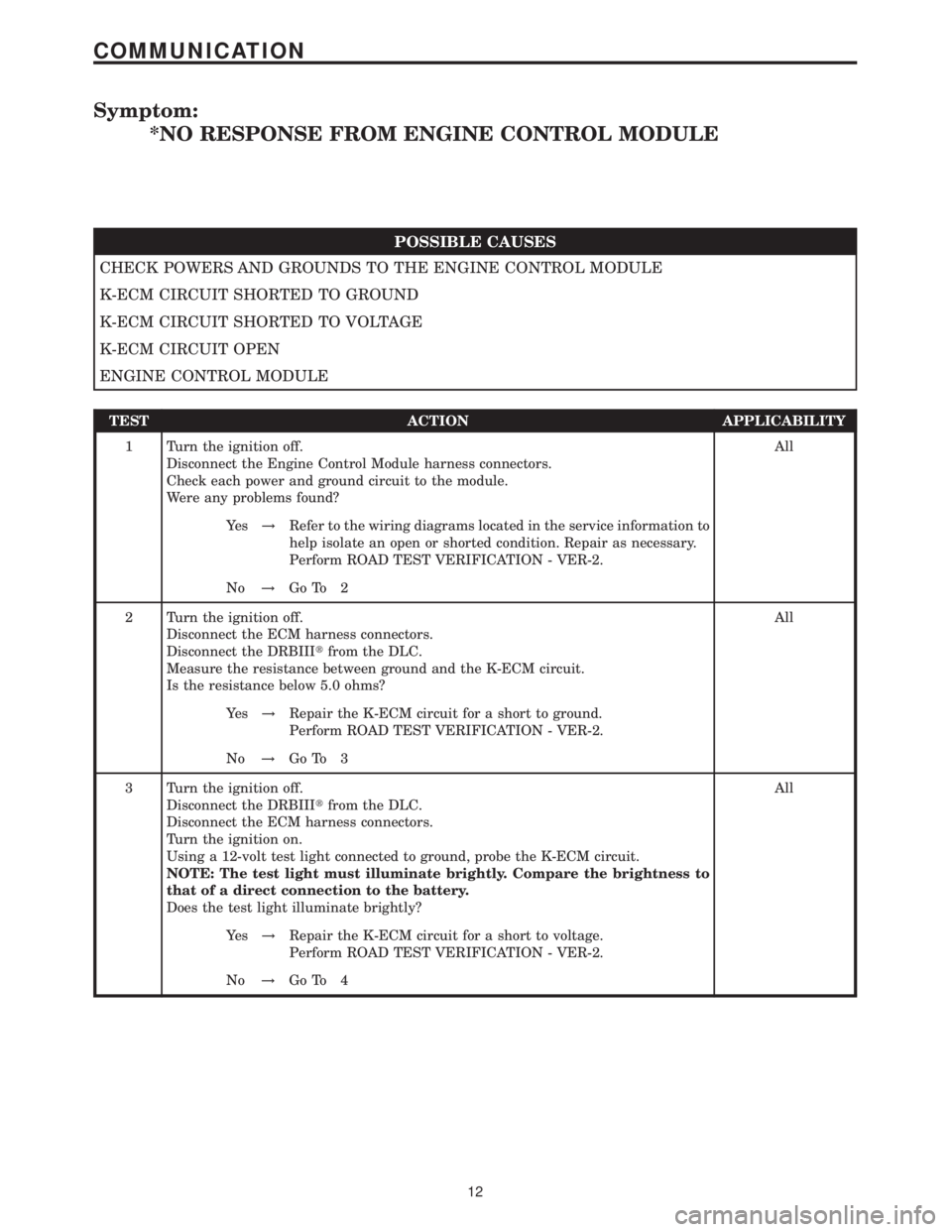
Symptom:
*NO RESPONSE FROM ENGINE CONTROL MODULE
POSSIBLE CAUSES
CHECK POWERS AND GROUNDS TO THE ENGINE CONTROL MODULE
K-ECM CIRCUIT SHORTED TO GROUND
K-ECM CIRCUIT SHORTED TO VOLTAGE
K-ECM CIRCUIT OPEN
ENGINE CONTROL MODULE
TEST ACTION APPLICABILITY
1 Turn the ignition off.
Disconnect the Engine Control Module harness connectors.
Check each power and ground circuit to the module.
Were any problems found?All
Ye s!Refer to the wiring diagrams located in the service information to
help isolate an open or shorted condition. Repair as necessary.
Perform ROAD TEST VERIFICATION - VER-2.
No!Go To 2
2 Turn the ignition off.
Disconnect the ECM harness connectors.
Disconnect the DRBIIItfrom the DLC.
Measure the resistance between ground and the K-ECM circuit.
Is the resistance below 5.0 ohms?All
Ye s!Repair the K-ECM circuit for a short to ground.
Perform ROAD TEST VERIFICATION - VER-2.
No!Go To 3
3 Turn the ignition off.
Disconnect the DRBIIItfrom the DLC.
Disconnect the ECM harness connectors.
Turn the ignition on.
Using a 12-volt test light connected to ground, probe the K-ECM circuit.
NOTE: The test light must illuminate brightly. Compare the brightness to
that of a direct connection to the battery.
Does the test light illuminate brightly?All
Ye s!Repair the K-ECM circuit for a short to voltage.
Perform ROAD TEST VERIFICATION - VER-2.
No!Go To 4
12
COMMUNICATION
Page 436 of 2305
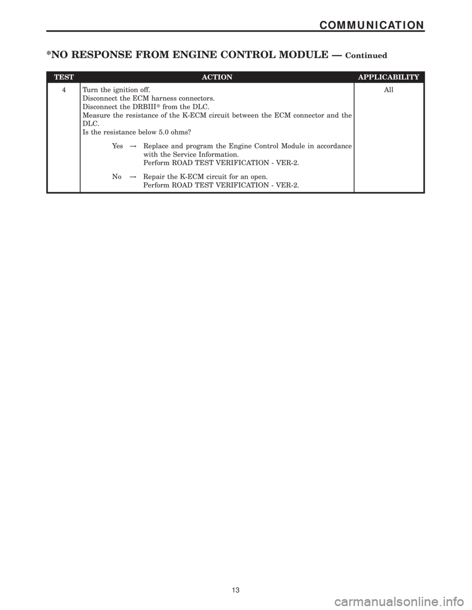
TEST ACTION APPLICABILITY
4 Turn the ignition off.
Disconnect the ECM harness connectors.
Disconnect the DRBIIItfrom the DLC.
Measure the resistance of the K-ECM circuit between the ECM connector and the
DLC.
Is the resistance below 5.0 ohms?All
Ye s!Replace and program the Engine Control Module in accordance
with the Service Information.
Perform ROAD TEST VERIFICATION - VER-2.
No!Repair the K-ECM circuit for an open.
Perform ROAD TEST VERIFICATION - VER-2.
13
COMMUNICATION
*NO RESPONSE FROM ENGINE CONTROL MODULE ÐContinued
Page 437 of 2305
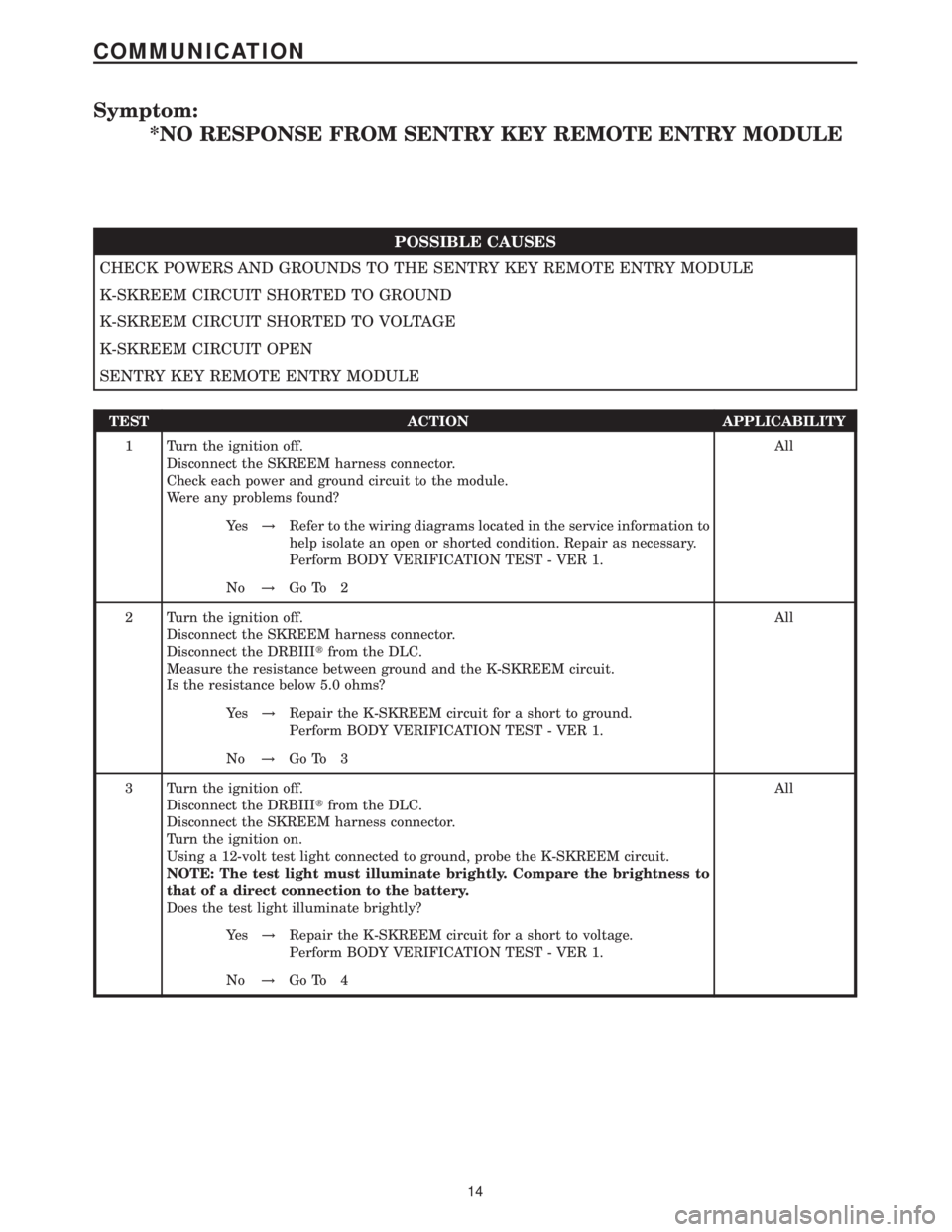
Symptom:
*NO RESPONSE FROM SENTRY KEY REMOTE ENTRY MODULE
POSSIBLE CAUSES
CHECK POWERS AND GROUNDS TO THE SENTRY KEY REMOTE ENTRY MODULE
K-SKREEM CIRCUIT SHORTED TO GROUND
K-SKREEM CIRCUIT SHORTED TO VOLTAGE
K-SKREEM CIRCUIT OPEN
SENTRY KEY REMOTE ENTRY MODULE
TEST ACTION APPLICABILITY
1 Turn the ignition off.
Disconnect the SKREEM harness connector.
Check each power and ground circuit to the module.
Were any problems found?All
Ye s!Refer to the wiring diagrams located in the service information to
help isolate an open or shorted condition. Repair as necessary.
Perform BODY VERIFICATION TEST - VER 1.
No!Go To 2
2 Turn the ignition off.
Disconnect the SKREEM harness connector.
Disconnect the DRBIIItfrom the DLC.
Measure the resistance between ground and the K-SKREEM circuit.
Is the resistance below 5.0 ohms?All
Ye s!Repair the K-SKREEM circuit for a short to ground.
Perform BODY VERIFICATION TEST - VER 1.
No!Go To 3
3 Turn the ignition off.
Disconnect the DRBIIItfrom the DLC.
Disconnect the SKREEM harness connector.
Turn the ignition on.
Using a 12-volt test light connected to ground, probe the K-SKREEM circuit.
NOTE: The test light must illuminate brightly. Compare the brightness to
that of a direct connection to the battery.
Does the test light illuminate brightly?All
Ye s!Repair the K-SKREEM circuit for a short to voltage.
Perform BODY VERIFICATION TEST - VER 1.
No!Go To 4
14
COMMUNICATION
Page 438 of 2305
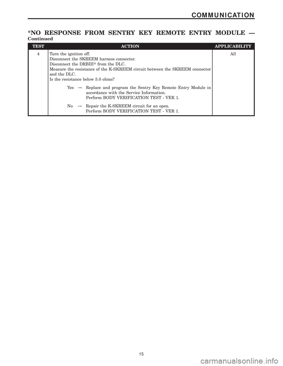
TEST ACTION APPLICABILITY
4 Turn the ignition off.
Disconnect the SKREEM harness connector.
Disconnect the DRBIIItfrom the DLC.
Measure the resistance of the K-SKREEM circuit between the SKREEM connector
and the DLC.
Is the resistance below 5.0 ohms?All
Ye s!Replace and program the Sentry Key Remote Entry Module in
accordance with the Service Information.
Perform BODY VERIFICATION TEST - VER 1.
No!Repair the K-SKREEM circuit for an open.
Perform BODY VERIFICATION TEST - VER 1.
15
COMMUNICATION
*NO RESPONSE FROM SENTRY KEY REMOTE ENTRY MODULE Ð
Continued
Page 488 of 2305
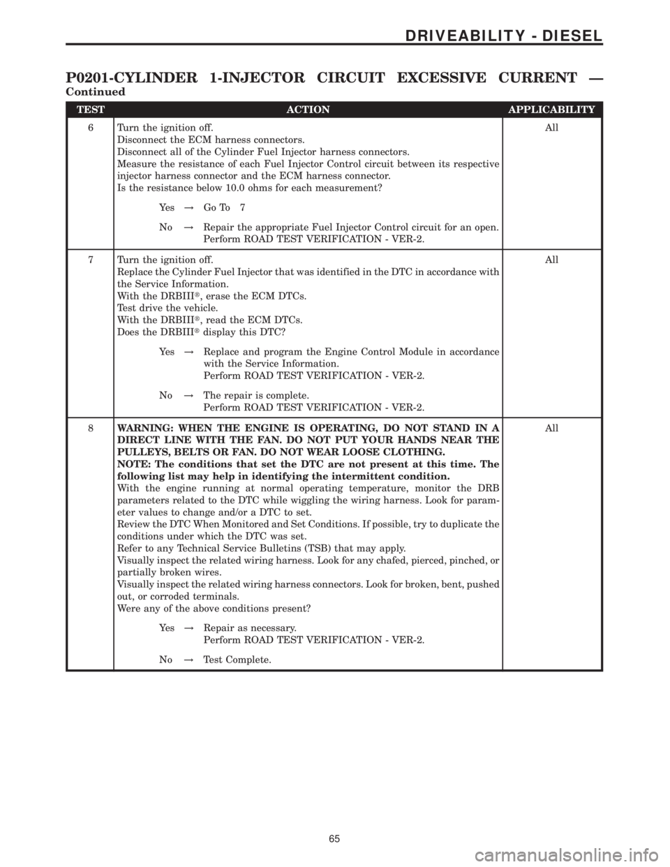
TEST ACTION APPLICABILITY
6 Turn the ignition off.
Disconnect the ECM harness connectors.
Disconnect all of the Cylinder Fuel Injector harness connectors.
Measure the resistance of each Fuel Injector Control circuit between its respective
injector harness connector and the ECM harness connector.
Is the resistance below 10.0 ohms for each measurement?All
Ye s!Go To 7
No!Repair the appropriate Fuel Injector Control circuit for an open.
Perform ROAD TEST VERIFICATION - VER-2.
7 Turn the ignition off.
Replace the Cylinder Fuel Injector that was identified in the DTC in accordance with
the Service Information.
With the DRBIIIt, erase the ECM DTCs.
Test drive the vehicle.
With the DRBIIIt, read the ECM DTCs.
Does the DRBIIItdisplay this DTC?All
Ye s!Replace and program the Engine Control Module in accordance
with the Service Information.
Perform ROAD TEST VERIFICATION - VER-2.
No!The repair is complete.
Perform ROAD TEST VERIFICATION - VER-2.
8WARNING: WHEN THE ENGINE IS OPERATING, DO NOT STAND IN A
DIRECT LINE WITH THE FAN. DO NOT PUT YOUR HANDS NEAR THE
PULLEYS, BELTS OR FAN. DO NOT WEAR LOOSE CLOTHING.
NOTE: The conditions that set the DTC are not present at this time. The
following list may help in identifying the intermittent condition.
With the engine running at normal operating temperature, monitor the DRB
parameters related to the DTC while wiggling the wiring harness. Look for param-
eter values to change and/or a DTC to set.
Review the DTC When Monitored and Set Conditions. If possible, try to duplicate the
conditions under which the DTC was set.
Refer to any Technical Service Bulletins (TSB) that may apply.
Visually inspect the related wiring harness. Look for any chafed, pierced, pinched, or
partially broken wires.
Visually inspect the related wiring harness connectors. Look for broken, bent, pushed
out, or corroded terminals.
Were any of the above conditions present?All
Ye s!Repair as necessary.
Perform ROAD TEST VERIFICATION - VER-2.
No!Test Complete.
65
DRIVEABILITY - DIESEL
P0201-CYLINDER 1-INJECTOR CIRCUIT EXCESSIVE CURRENT Ð
Continued
Page 707 of 2305
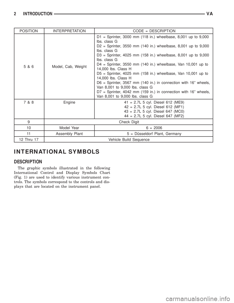
POSITION INTERPRETATION CODE = DESCRIPTION
5 & 6 Model, Cab, WeightD1 = Sprinter, 3000 mm (118 in.) wheelbase, 8,001 up to 9,000
lbs. class G
D2 = Sprinter, 3550 mm (140 in.) wheelbase, 8,001 up to 9,000
lbs. class G
D3 = Sprinter, 4025 mm (158 in.) wheelbase, 8,001 up to 9,000
lbs. class G
D4 = Sprinter, 3550 mm (140 in.) wheelbase, Van 10,001 up to
14,000 lbs. Class H
D5 = Sprinter, 4025 mm (158 in.) wheelbase, Van 10,001 up to
14,000 lbs. Class H
D6 = Sprinter, 3567 mm (140 in.) in connection with 16º wheels,
Van 8,001 to 9,000 lbs. class G
D7 = Sprinter, 4042 mm (159 in.) in connection with 16º wheels,
Van 8,001 to 9,000 lbs. class G
7 & 8 Engine 41 = 2.7L 5 cyl. Diesel 612 (ME9)
42 = 2.7L 5 cyl. Diesel 612 (MF1)
43 = 2.7L 5 cyl. Diesel 647 (MC0)
44 = 2.7L 5 cyl. Diesel 647 (MF2)
9 Check Digit
10 Model Year 6 = 2006
11 Assembly Plant 5 = Dîsseldorf Plant, Germany
12 Thru 17 Vehicle Build Sequence
INTERNATIONAL SYMBOLS
DESCRIPTION
The graphic symbols illustrated in the following
International Control and Display Symbols Chart
(Fig. 1) are used to identify various instrument con-
trols. The symbols correspond to the controls and dis-
plays that are located on the instrument panel.
2 INTRODUCTIONVA