2006 MERCEDES-BENZ SPRINTER ESP
[x] Cancel search: ESPPage 138 of 2305

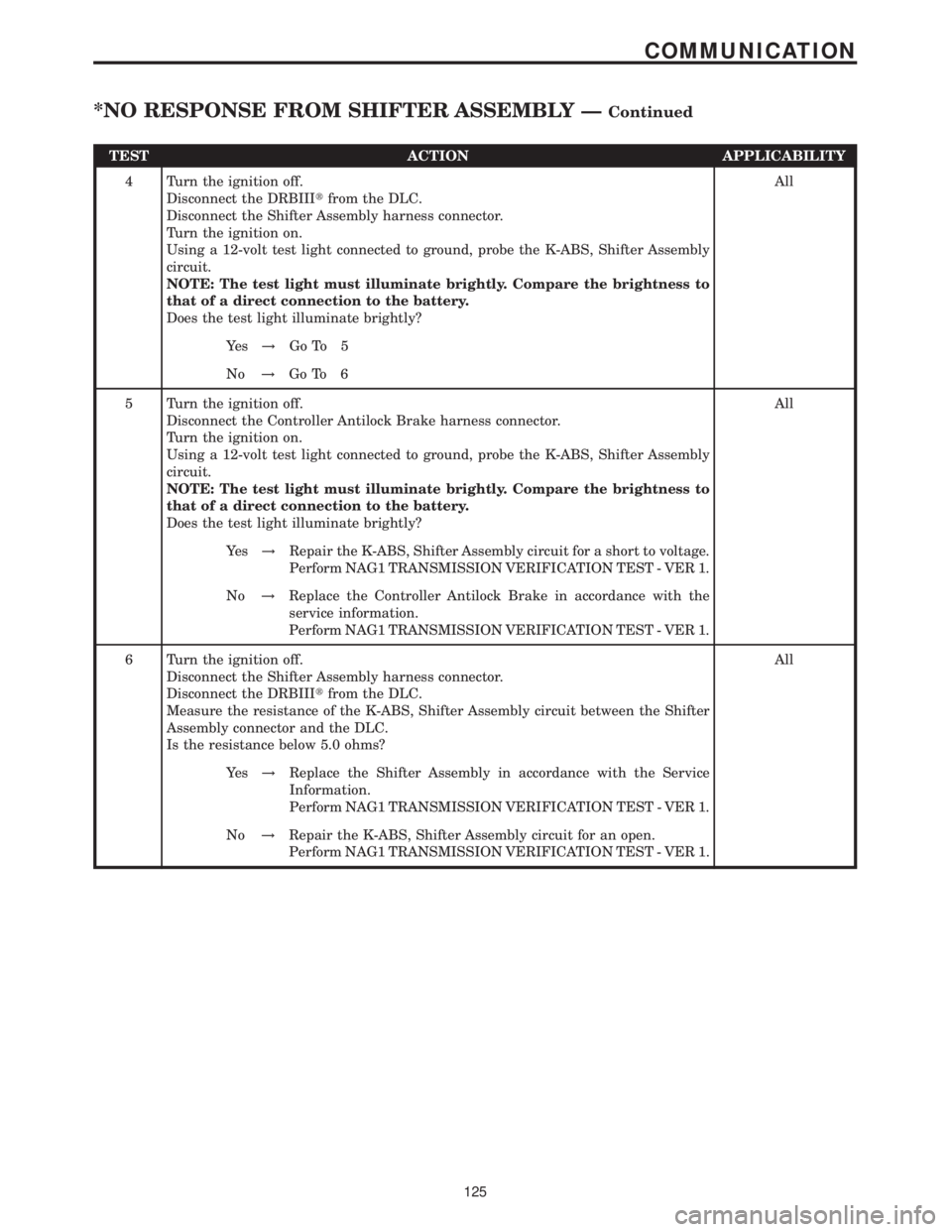
TEST ACTION APPLICABILITY
4 Turn the ignition off.
Disconnect the DRBIIItfrom the DLC.
Disconnect the Shifter Assembly harness connector.
Turn the ignition on.
Using a 12-volt test light connected to ground, probe the K-ABS, Shifter Assembly
circuit.
NOTE: The test light must illuminate brightly. Compare the brightness to
that of a direct connection to the battery.
Does the test light illuminate brightly?All
Ye s!Go To 5
No!Go To 6
5 Turn the ignition off.
Disconnect the Controller Antilock Brake harness connector.
Turn the ignition on.
Using a 12-volt test light connected to ground, probe the K-ABS, Shifter Assembly
circuit.
NOTE: The test light must illuminate brightly. Compare the brightness to
that of a direct connection to the battery.
Does the test light illuminate brightly?All
Ye s!Repair the K-ABS, Shifter Assembly circuit for a short to voltage.
Perform NAG1 TRANSMISSION VERIFICATION TEST - VER 1.
No!Replace the Controller Antilock Brake in accordance with the
service information.
Perform NAG1 TRANSMISSION VERIFICATION TEST - VER 1.
6 Turn the ignition off.
Disconnect the Shifter Assembly harness connector.
Disconnect the DRBIIItfrom the DLC.
Measure the resistance of the K-ABS, Shifter Assembly circuit between the Shifter
Assembly connector and the DLC.
Is the resistance below 5.0 ohms?All
Ye s!Replace the Shifter Assembly in accordance with the Service
Information.
Perform NAG1 TRANSMISSION VERIFICATION TEST - VER 1.
No!Repair the K-ABS, Shifter Assembly circuit for an open.
Perform NAG1 TRANSMISSION VERIFICATION TEST - VER 1.
125
COMMUNICATION
*NO RESPONSE FROM SHIFTER ASSEMBLY ÐContinued
Page 139 of 2305

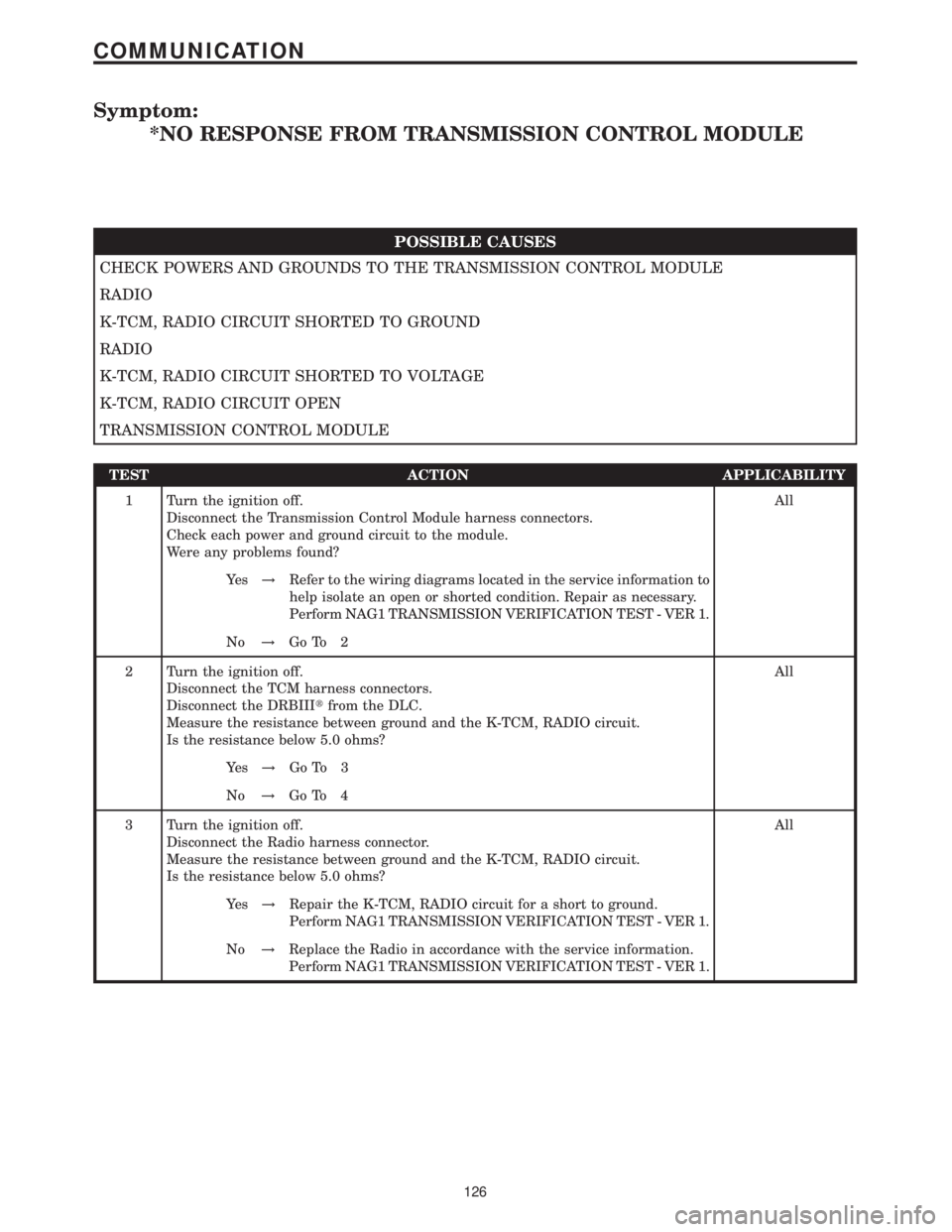
Symptom:
*NO RESPONSE FROM TRANSMISSION CONTROL MODULE
POSSIBLE CAUSES
CHECK POWERS AND GROUNDS TO THE TRANSMISSION CONTROL MODULE
RADIO
K-TCM, RADIO CIRCUIT SHORTED TO GROUND
RADIO
K-TCM, RADIO CIRCUIT SHORTED TO VOLTAGE
K-TCM, RADIO CIRCUIT OPEN
TRANSMISSION CONTROL MODULE
TEST ACTION APPLICABILITY
1 Turn the ignition off.
Disconnect the Transmission Control Module harness connectors.
Check each power and ground circuit to the module.
Were any problems found?All
Ye s!Refer to the wiring diagrams located in the service information to
help isolate an open or shorted condition. Repair as necessary.
Perform NAG1 TRANSMISSION VERIFICATION TEST - VER 1.
No!Go To 2
2 Turn the ignition off.
Disconnect the TCM harness connectors.
Disconnect the DRBIIItfrom the DLC.
Measure the resistance between ground and the K-TCM, RADIO circuit.
Is the resistance below 5.0 ohms?All
Ye s!Go To 3
No!Go To 4
3 Turn the ignition off.
Disconnect the Radio harness connector.
Measure the resistance between ground and the K-TCM, RADIO circuit.
Is the resistance below 5.0 ohms?All
Ye s!Repair the K-TCM, RADIO circuit for a short to ground.
Perform NAG1 TRANSMISSION VERIFICATION TEST - VER 1.
No!Replace the Radio in accordance with the service information.
Perform NAG1 TRANSMISSION VERIFICATION TEST - VER 1.
126
COMMUNICATION
Page 140 of 2305

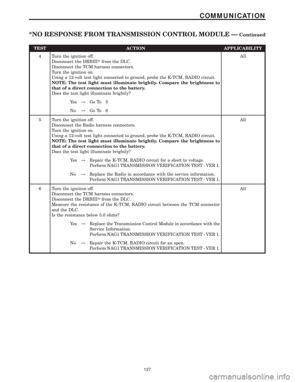
TEST ACTION APPLICABILITY
4 Turn the ignition off.
Disconnect the DRBIIItfrom the DLC.
Disconnect the TCM harness connectors.
Turn the ignition on.
Using a 12-volt test light connected to ground, probe the K-TCM, RADIO circuit.
NOTE: The test light must illuminate brightly. Compare the brightness to
that of a direct connection to the battery.
Does the test light illuminate brightly?All
Ye s!Go To 5
No!Go To 6
5 Turn the ignition off.
Disconnect the Radio harness connectors.
Turn the ignition on.
Using a 12-volt test light connected to ground, probe the K-TCM, RADIO circuit.
NOTE: The test light must illuminate brightly. Compare the brightness to
that of a direct connection to the battery.
Does the test light illuminate brightly?All
Ye s!Repair the K-TCM, RADIO circuit for a short to voltage.
Perform NAG1 TRANSMISSION VERIFICATION TEST - VER 1.
No!Replace the Radio in accordance with the service information.
Perform NAG1 TRANSMISSION VERIFICATION TEST - VER 1.
6 Turn the ignition off.
Disconnect the TCM harness connectors.
Disconnect the DRBIIItfrom the DLC.
Measure the resistance of the K-TCM, RADIO circuit between the TCM connector
and the DLC.
Is the resistance below 5.0 ohms?All
Ye s!Replace the Transmission Control Module in accordance with the
Service Information.
Perform NAG1 TRANSMISSION VERIFICATION TEST - VER 1.
No!Repair the K-TCM, RADIO circuit for an open.
Perform NAG1 TRANSMISSION VERIFICATION TEST - VER 1.
127
COMMUNICATION
*NO RESPONSE FROM TRANSMISSION CONTROL MODULE ÐContinued
Page 188 of 2305

Symptom:
WATER CYCLE VALVE CONTROL HIGH OR OPEN (ACTIVE)
POSSIBLE CAUSES
WATER CYCLE VALVE
WATER CYCLE VALVE CONTROL CIRCUIT SHORTED TO VOLTAGE
AUTOMATIC TEMPERATURE CONTROL (ATC)
WATER CYCLE VALVE CONTROL CIRCUIT OPEN
GROUND CIRCUIT OPEN
AUTOMATIC TEMPERATURE CONTROL (ATC)
TEST ACTION APPLICABILITY
1 Turn the ignition off.
Press the Residual Engine Heat Utilization (REST) switch off.
NOTE: Check connectors - Clean/repair as necessary.
Disconnect the Water Cycle Valve harness connector.
Connect a 12-volt test light between the Water Cycle Valve Control circuit and the
Ground circuit in the Water Cycle Valve harness connector. The test light should
operate as follows:
With the Residual Engine Heat Utilization (REST) switch off, the test light should
not illuminate.
Press the Residual Engine Heat Utilization (REST) switch on.
With the Blend control set to Full Cold, the test light should illuminate brightly and
continuously.
With the Blend control set to one position below the half Cold/Hot setting, the test
light should illuminate brightly and blink at a slow continuous rate.
With the Blend control set to the half Cold/Hot setting or above, the test light should
be off.
Does the test light operate as specified?All
Ye s!Replace the Water Cycle Valve in accordance with the Service
Information.
Perform BODY VERIFICATION TEST - VER 1.
No, Light Illuminates With REST Off.
Go To 2
No, Light Will Not Illuminate
Go To 3
No, Light Won't Correspond To Blend
Go To 3
175
HEATING & A/C
Page 254 of 2305

TEST ACTION APPLICABILITY
8 Turn the ignition off.
NOTE: The Rain Sensor Module (RSM) is mounted above the accelerator
pedal assembly.
Disconnect the Rain Sensor Module harness connector.
Turn the ignition on.
Using a 12-volt test light connected to ground, check the Battery Supply circuit at the
Rain Sensor Module harness connector cavity A-1.
Does the test light illuminate brightly?All
Ye s!Go To 9
No!Repair the open 12 Volt Power Supply circuit.
9 Turn the ignition off.
Disconnect the Rain Sensor Module harness connector.
Using a 12-volt test light connected to 12 volts, check the Ground circuit at the Rain
Sensor Module harness connector cavity C-1.
Does the test light illuminate brightly?All
Ye s!Go To 10
No!Repair the open Ground circuit.
10 Turn the ignition off.
Disconnect the Rain Sensor Module harness connector.
Turn the ignition on.
Refer to the Wiper/Washer Switch Voltage Chart in Charts and Graphs to verify
correct wiper switch voltage signals to the Rain Sensor Module when the wiper
switch is adjusted to each of the four positions.
Do voltage readings at the RSM connector correspond correctly to voltages specified
in the chart?All
Ye s!Go To 11
No!Refer to the Rain Sensor/Wiper System Schematic in Charts and
Graphs to diagnose base wiper system problem with the circuit(s)
that did not have the correct corresponding voltage to the chart.
11 Turn the ignition off.
Disconnect the wiper motor harness connector.
Using a 12-volt test light connected to 12-volts, check the Ground circuit at the Wiper
Motor harness connector.
Does the test light illuminate brightly?All
Ye s!Go To 12
No!Repair the Wiper Motor Ground circuit for an open.
241
WINDSHIELD WIPER & WASHER
CHECKING THE RAIN SENSOR/WIPER OPERATION ÐContinued
Page 259 of 2305

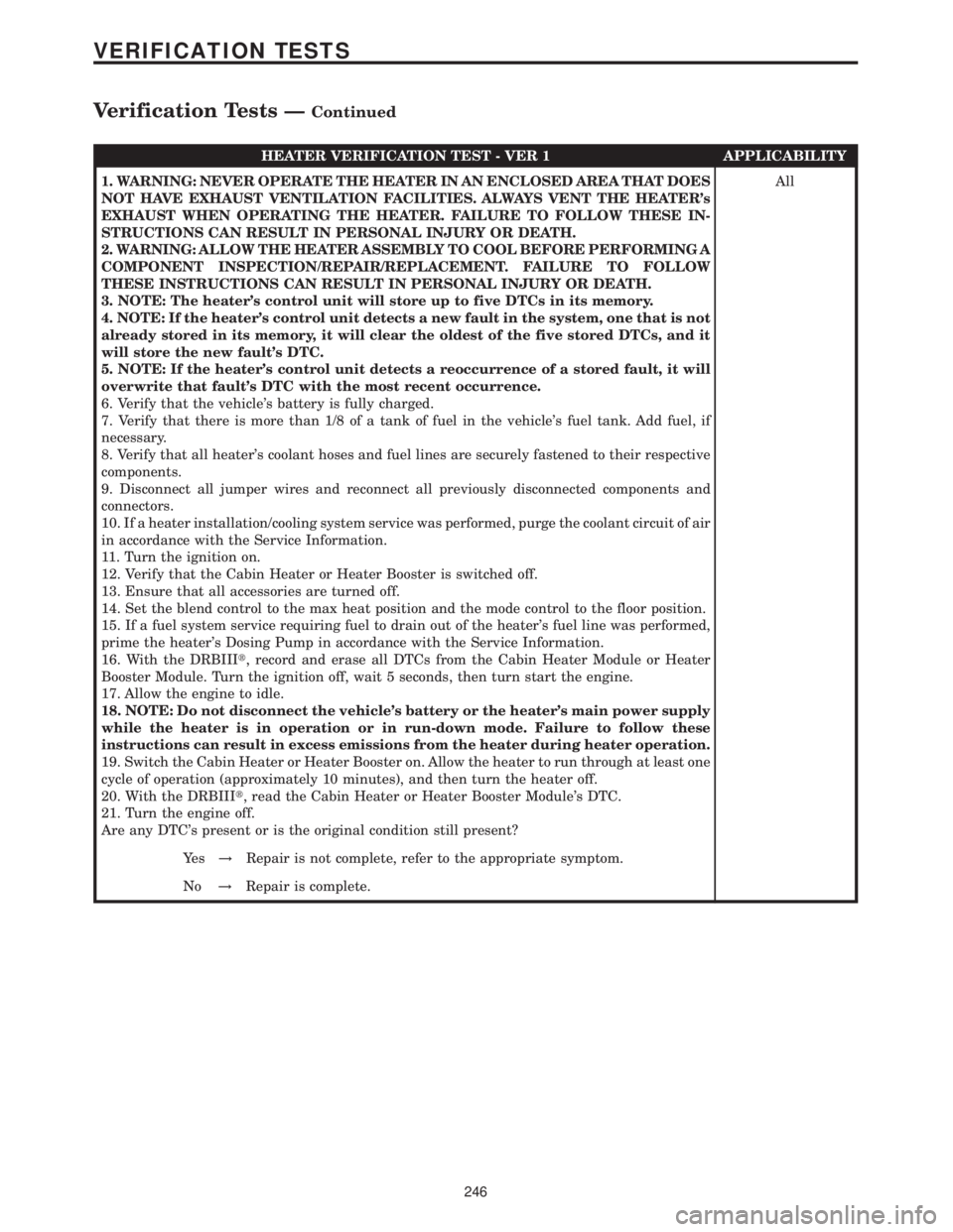
HEATER VERIFICATION TEST - VER 1 APPLICABILITY
1. WARNING: NEVER OPERATE THE HEATER IN AN ENCLOSED AREA THAT DOES
NOT HAVE EXHAUST VENTILATION FACILITIES. ALWAYS VENT THE HEATER's
EXHAUST WHEN OPERATING THE HEATER. FAILURE TO FOLLOW THESE IN-
STRUCTIONS CAN RESULT IN PERSONAL INJURY OR DEATH.
2. WARNING: ALLOW THE HEATER ASSEMBLY TO COOL BEFORE PERFORMING A
COMPONENT INSPECTION/REPAIR/REPLACEMENT. FAILURE TO FOLLOW
THESE INSTRUCTIONS CAN RESULT IN PERSONAL INJURY OR DEATH.
3. NOTE: The heater's control unit will store up to five DTCs in its memory.
4. NOTE: If the heater's control unit detects a new fault in the system, one that is not
already stored in its memory, it will clear the oldest of the five stored DTCs, and it
will store the new fault's DTC.
5. NOTE: If the heater's control unit detects a reoccurrence of a stored fault, it will
overwrite that fault's DTC with the most recent occurrence.
6. Verify that the vehicle's battery is fully charged.
7. Verify that there is more than 1/8 of a tank of fuel in the vehicle's fuel tank. Add fuel, if
necessary.
8. Verify that all heater's coolant hoses and fuel lines are securely fastened to their respective
components.
9. Disconnect all jumper wires and reconnect all previously disconnected components and
connectors.
10. If a heater installation/cooling system service was performed, purge the coolant circuit of air
in accordance with the Service Information.
11. Turn the ignition on.
12. Verify that the Cabin Heater or Heater Booster is switched off.
13. Ensure that all accessories are turned off.
14. Set the blend control to the max heat position and the mode control to the floor position.
15. If a fuel system service requiring fuel to drain out of the heater's fuel line was performed,
prime the heater's Dosing Pump in accordance with the Service Information.
16. With the DRBIIIt, record and erase all DTCs from the Cabin Heater Module or Heater
Booster Module. Turn the ignition off, wait 5 seconds, then turn start the engine.
17. Allow the engine to idle.
18. NOTE: Do not disconnect the vehicle's battery or the heater's main power supply
while the heater is in operation or in run-down mode. Failure to follow these
instructions can result in excess emissions from the heater during heater operation.
19. Switch the Cabin Heater or Heater Booster on. Allow the heater to run through at least one
cycle of operation (approximately 10 minutes), and then turn the heater off.
20. With the DRBIIIt, read the Cabin Heater or Heater Booster Module's DTC.
21. Turn the engine off.
Are any DTC's present or is the original condition still present?All
Ye s!Repair is not complete, refer to the appropriate symptom.
No!Repair is complete.
246
VERIFICATION TESTS
Verification Tests ÐContinued
Page 318 of 2305

TABLE OF CONTENTS
1.0 INTRODUCTION.........................................................1
1.1SYSTEM COVERAGE...............................................1
1.2SIX-STEP TROUBLESHOOTING PROCEDURE..........................1
2.0 INDENTIFICATION OF SYSTEM............................................1
3.0 SYSTEM DESCRIPTION AND FUNCTIONAL OPERATION......................1
3.1ESP ..............................................................1
3.2ABS ..............................................................1
3.3BRAKE ASSIST SYSTEM (HBA).......................................2
3.4TCS (ASR).........................................................2
3.5ELECTRONIC BRAKE DISTRIBUTION (EBD)............................2
3.6VEHICLE CONTROLLING (FZR).......................................2
3.7SYSTEM COMPONENTS.............................................2
3.7.1ABS AND TCS (ASR) INDICATORS............................3
3.7.2CONTROLLER ANTILOCK BRAKE (CAB).......................3
3.7.3HYDRAULIC CONTROL UNIT (HCU)...........................3
3.7.4SWITCHES/SENSORS.......................................3
3.7.5SELF TESTS...............................................4
3.8USING THE DRBIIIT.................................................4
3.9DRBIIITERROR MESSAGES.........................................4
3.9.1DRBIIITDOES NOT POWER UP (BLANK SCREEN)...............5
3.9.2DISPLAY IS NOT VISIBLE....................................5
4.0 DISCLAIMERS, SAFETY, WARNINGS.......................................5
4.1DISCLAIMERS......................................................5
4.2SAFETY...........................................................5
4.2.1TECHNICIAN SAFETY INFORMATION..........................5
4.2.2VEHICLE PREPARATION FOR TESTING........................5
4.2.3SERVICING SUB-ASSEMBLIES...............................5
4.2.4DRBIIITSAFETY INFORMATION...............................6
4.3WARNING.........................................................6
4.3.1VEHICLE DAMAGE WARNINGS...............................6
4.3.2ROAD TESTING A COMPLAINT VEHICLE.......................6
4.4DIAGNOSIS........................................................6
5.0 REQUIRED TOOLS AND EQUIPMENT......................................7
6.0 GLOSSARY OF TERMS...................................................7
7.0 DIAGNOSTIC INFORMATION AND PROCEDURES............................9
BRAKES (CAB)
ANTI-LOCK BRAKE MODULE INTERNAL...................................10
CAB INTERNAL.........................................................10
BRAKE FLUID LEVEL....................................................13
BRAKE PRESSURE SENSOR CIRCUIT.....................................15
BRAKE SWITCH CIRCUIT................................................17
CAB CHECK SUM......................................................21
CAB OPTION...........................................................23
CAN COMMUNICATION ERROR..........................................25
i
Page 320 of 2305

TABLE OF CONTENTS - Continued
9.0 CONNECTOR PINOUTS.................................................83
BRAKE FLUID LEVEL SWITCH............................................83
BRAKE LAMP SWITCH C1 (EXCEPT ESP)..................................83
BRAKE LAMP SWITCH C2 (EXCEPT ESP) - BLACK..........................83
CONTROLLER ANTILOCK BRAKE.........................................84
INSTRUMENT CLUSTER C2 - WHITE......................................85
STEERING ANGLE SENSOR..............................................85
TCS SWITCH (ASR) - BLACK.............................................85
WHEEL SPEED SENSOR-LEFT FRONT....................................85
WHEEL SPEED SENSOR-LEFT REAR......................................86
WHEEL SPEED SENSOR-RIGHT FRONT...................................86
WHEEL SPEED SENSOR-RIGHT REAR....................................86
10.0 SCHEMATIC DIAGRAMS.................................................87
10.1BOSCH 5.7 ANTILOCK BRAKE SYSTEM ± ABS.........................87
iii