2006 MERCEDES-BENZ SPRINTER ESP
[x] Cancel search: ESPPage 1725 of 2305
INSTALLATION
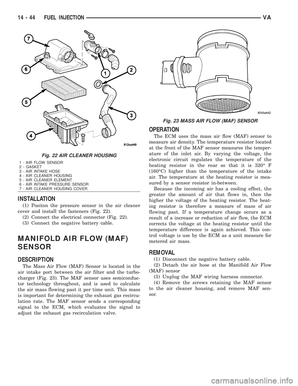
(1) Positon the pressure sensor in the air cleaner
cover and install the fasteners (Fig. 22).
(2) Connect the electrical connector (Fig. 22).
(3) Connect the negative battery cable.
MANIFOLD AIR FLOW (MAF)
SENSOR
DESCRIPTION
The Mass Air Flow (MAF) Sensor is located in the
air intake port between the air filter and the turbo-
charger (Fig. 23). The MAF sensor uses semiconduc-
tor technology throughout, and is used to calculate
the air mass flowing past it per time unit. This mass
is important for determining the exhaust gas recircu-
lation rate. The MAF sensor sends a corresponding
signal to the ECM, which evaluates the signal to
adjust the exhaust gas recirculation valve.
OPERATION
The ECM uses the mass air flow (MAF) sensor to
measure air density. The temperature resistor located
at the front of the MAF sensor measures the temper-
ature of the inlet air. By varying the voltage, the
electronic circuit regulates the temperature of the
heating resistor in the rear so that it is 320É F
(160ÉC) higher than the temperature of the intake
air. The temperature at the heating resistor is mea-
sured by a sensor resistor in-between.
Because the incoming air has a cooling effect, the
greater the amount of air that flows in, then the
higher the voltage of the heating resistor. The heat-
ing resistor is therefore a measure of mass of air
flowing past. If a temperature change occurs as a
result of a increase or reduction of air flow, the ECM
corrects the voltage at the heating resistor until the
temperature difference is again achieved. This con-
trol voltage is use by the ECM as a unit measure for
metered air mass.
REMOVAL
(1) Disconnect the negative battery cable.
(2) Detach the air hose at the Manifold Air Flow
(MAF) sensor
(3) Unplug the MAF wiring harness connector.
(4) Remove the screws retaining the MAF sensor
to the air cleaner housing, and remove MAF sen-
sor.
Fig. 22 AIR CLEANER HOUSING
1 - AIR FLOW SENSOR
2 - GASKET
3 - AIR INTAKE HOSE
4 - AIR CLEANER HOUSING
5 - AIR CLEANER ELEMENT
6 - AIR INTAKE PRESSURE SENSOR
7 - AIR CLEANER HOUSING COVER
Fig. 23 MASS AIR FLOW (MAF) SENSOR
14 - 44 FUEL INJECTIONVA
Page 1726 of 2305
INSTALLATION
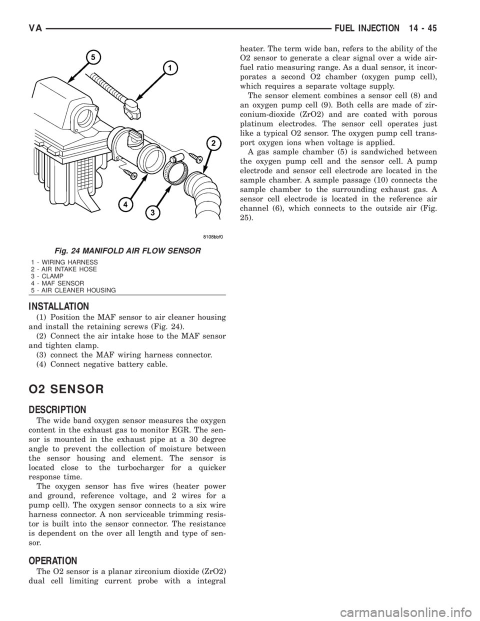
(1) Position the MAF sensor to air cleaner housing
and install the retaining screws (Fig. 24).
(2) Connect the air intake hose to the MAF sensor
and tighten clamp.
(3) connect the MAF wiring harness connector.
(4) Connect negative battery cable.
O2 SENSOR
DESCRIPTION
The wide band oxygen sensor measures the oxygen
content in the exhaust gas to monitor EGR. The sen-
sor is mounted in the exhaust pipe at a 30 degree
angle to prevent the collection of moisture between
the sensor housing and element. The sensor is
located close to the turbocharger for a quicker
response time.
The oxygen sensor has five wires (heater power
and ground, reference voltage, and 2 wires for a
pump cell). The oxygen sensor connects to a six wire
harness connector. A non serviceable trimming resis-
tor is built into the sensor connector. The resistance
is dependent on the over all length and type of sen-
sor.
OPERATION
The O2 sensor is a planar zirconium dioxide (ZrO2)
dual cell limiting current probe with a integralheater. The term wide ban, refers to the ability of the
O2 sensor to generate a clear signal over a wide air-
fuel ratio measuring range. As a dual sensor, it incor-
porates a second O2 chamber (oxygen pump cell),
which requires a separate voltage supply.
The sensor element combines a sensor cell (8) and
an oxygen pump cell (9). Both cells are made of zir-
conium-dioxide (ZrO2) and are coated with porous
platinum electrodes. The sensor cell operates just
like a typical O2 sensor. The oxygen pump cell trans-
port oxygen ions when voltage is applied.
A gas sample chamber (5) is sandwiched between
the oxygen pump cell and the sensor cell. A pump
electrode and sensor cell electrode are located in the
sample chamber. A sample passage (10) connects the
sample chamber to the surrounding exhaust gas. A
sensor cell electrode is located in the reference air
channel (6), which connects to the outside air (Fig.
25).
Fig. 24 MANIFOLD AIR FLOW SENSOR
1 - WIRING HARNESS
2 - AIR INTAKE HOSE
3 - CLAMP
4 - MAF SENSOR
5 - AIR CLEANER HOUSING
VAFUEL INJECTION 14 - 45
Page 1728 of 2305
The sensor cell measures the difference between
the oxygen concentration in the gas sample chamber
and the oxygen concentration in the outside air from
the reference air channel. A small voltage is gener-
ated across the sensor, which is proportional to the
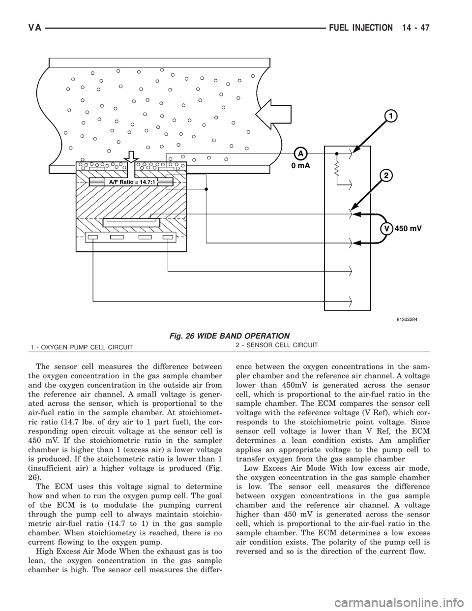
air-fuel ratio in the sample chamber. At stoichiomet-
ric ratio (14.7 lbs. of dry air to 1 part fuel), the cor-
responding open circuit voltage at the sensor cell is
450 mV. If the stoichiometric ratio in the sampler
chamber is higher than 1 (excess air) a lower voltage
is produced. If the stoichometric ratio is lower than 1
(insufficient air) a higher voltage is produced (Fig.
26).
The ECM uses this voltage signal to determine
how and when to run the oxygen pump cell. The goal
of the ECM is to modulate the pumping current
through the pump cell to always maintain stoichio-
metric air-fuel ratio (14.7 to 1) in the gas sample
chamber. When stoichiometry is reached, there is no
current flowing to the oxygen pump.
High Excess Air Mode When the exhaust gas is too
lean, the oxygen concentration in the gas sample
chamber is high. The sensor cell measures the differ-ence between the oxygen concentrations in the sam-
pler chamber and the reference air channel. A voltage
lower than 450mV is generated across the sensor
cell, which is proportional to the air-fuel ratio in the
sample chamber. The ECM compares the sensor cell
voltage with the reference voltage (V Ref), which cor-
responds to the stoichiometric point voltage. Since
sensor cell voltage is lower than V Ref, the ECM
determines a lean condition exists. Am amplifier
applies an appropriate voltage to the pump cell to
transfer oxygen from the gas sample chamber
Low Excess Air Mode With low excess air mode,
the oxygen concentration in the gas sample chamber
is low. The sensor cell measures the difference
between oxygen concentrations in the gas sample
chamber and the reference air channel. A voltage
higher than 450 mV is generated across the sensor
cell, which is proportional to the air-fuel ratio in the
sample chamber. The ECM determines a low excess
air condition exists. The polarity of the pump cell is
reversed and so is the direction of the current flow.
Fig. 26 WIDE BAND OPERATION
1 - OXYGEN PUMP CELL CIRCUIT2 - SENSOR CELL CIRCUIT
VAFUEL INJECTION 14 - 47
Page 1746 of 2305
AUTOMATIC TRANSMISSION NAG1 - SERVICE INFORMATION
DESCRIPTION
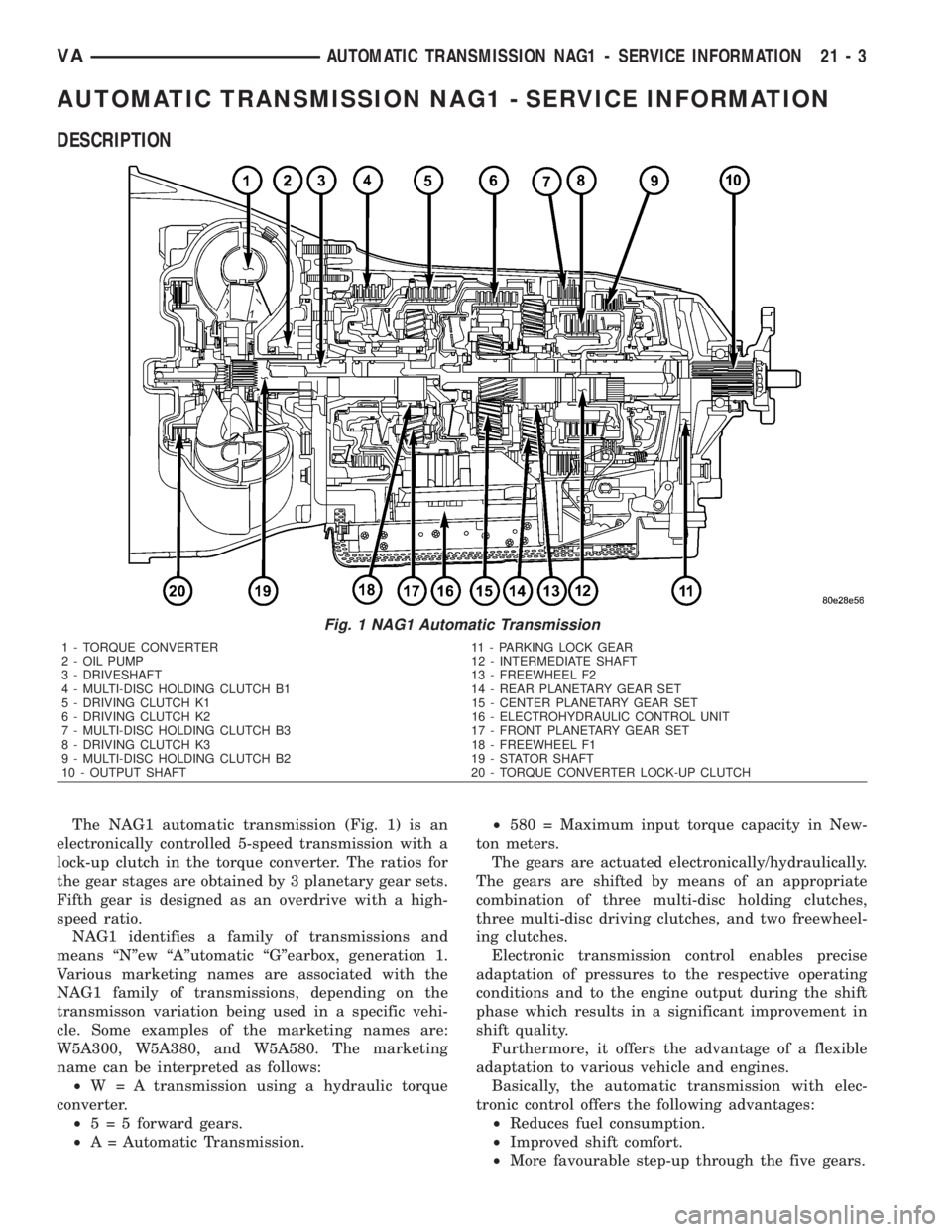
The NAG1 automatic transmission (Fig. 1) is an
electronically controlled 5-speed transmission with a
lock-up clutch in the torque converter. The ratios for
the gear stages are obtained by 3 planetary gear sets.
Fifth gear is designed as an overdrive with a high-
speed ratio.
NAG1 identifies a family of transmissions and
means ªNºew ªAºutomatic ªGºearbox, generation 1.
Various marketing names are associated with the
NAG1 family of transmissions, depending on the
transmisson variation being used in a specific vehi-
cle. Some examples of the marketing names are:
W5A300, W5A380, and W5A580. The marketing
name can be interpreted as follows:
²W = A transmission using a hydraulic torque
converter.
²5 = 5 forward gears.
²A = Automatic Transmission.²580 = Maximum input torque capacity in New-
ton meters.
The gears are actuated electronically/hydraulically.
The gears are shifted by means of an appropriate
combination of three multi-disc holding clutches,
three multi-disc driving clutches, and two freewheel-
ing clutches.
Electronic transmission control enables precise
adaptation of pressures to the respective operating
conditions and to the engine output during the shift
phase which results in a significant improvement in
shift quality.
Furthermore, it offers the advantage of a flexible
adaptation to various vehicle and engines.
Basically, the automatic transmission with elec-
tronic control offers the following advantages:
²Reduces fuel consumption.
²Improved shift comfort.
²More favourable step-up through the five gears.
Fig. 1 NAG1 Automatic Transmission
1 - TORQUE CONVERTER 11 - PARKING LOCK GEAR
2 - OIL PUMP 12 - INTERMEDIATE SHAFT
3 - DRIVESHAFT 13 - FREEWHEEL F2
4 - MULTI-DISC HOLDING CLUTCH B1 14 - REAR PLANETARY GEAR SET
5 - DRIVING CLUTCH K1 15 - CENTER PLANETARY GEAR SET
6 - DRIVING CLUTCH K2 16 - ELECTROHYDRAULIC CONTROL UNIT
7 - MULTI-DISC HOLDING CLUTCH B3 17 - FRONT PLANETARY GEAR SET
8 - DRIVING CLUTCH K3 18 - FREEWHEEL F1
9 - MULTI-DISC HOLDING CLUTCH B2 19 - STATOR SHAFT
10 - OUTPUT SHAFT 20 - TORQUE CONVERTER LOCK-UP CLUTCH
VAAUTOMATIC TRANSMISSION NAG1 - SERVICE INFORMATION 21 - 3
Page 1747 of 2305
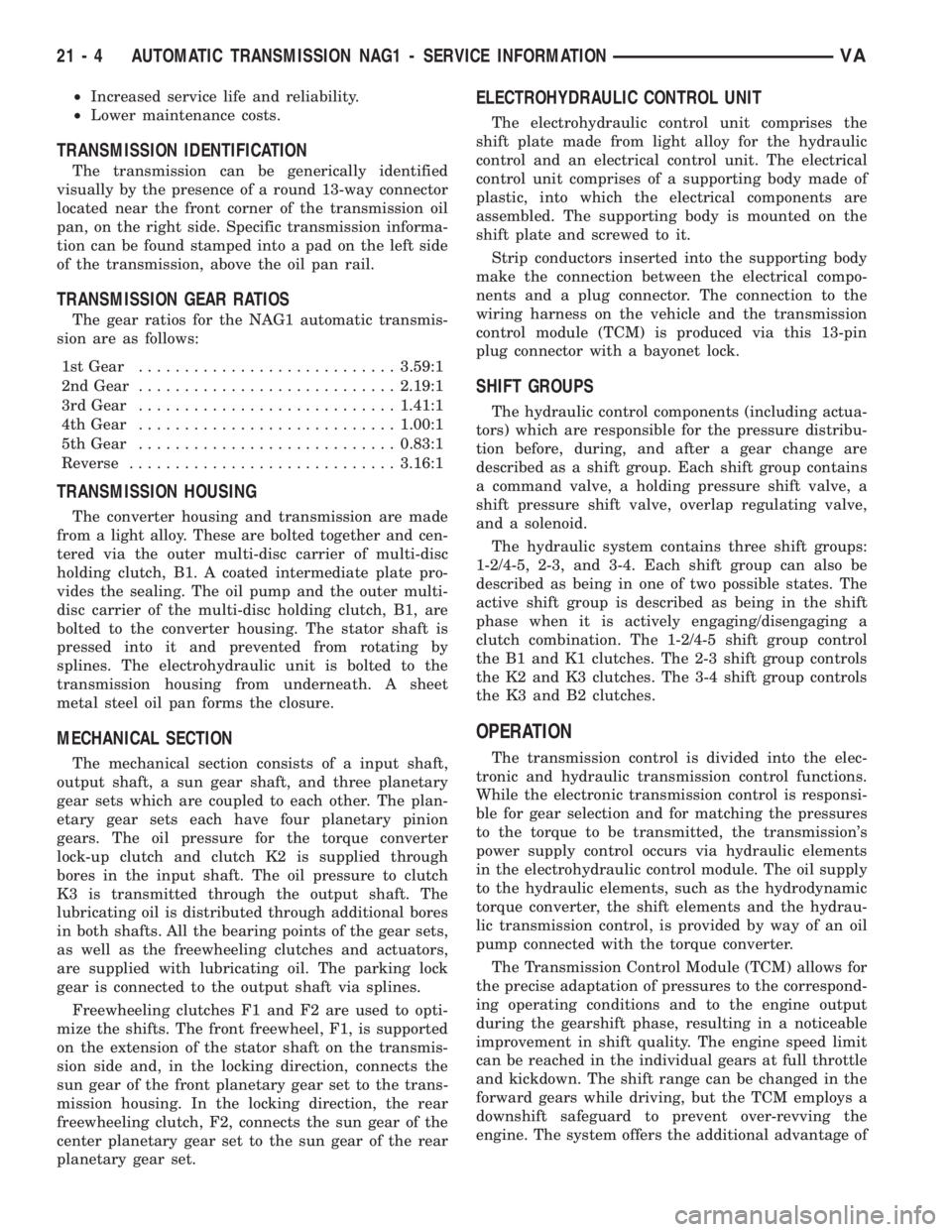
²Increased service life and reliability.
²Lower maintenance costs.
TRANSMISSION IDENTIFICATION
The transmission can be generically identified
visually by the presence of a round 13-way connector
located near the front corner of the transmission oil
pan, on the right side. Specific transmission informa-
tion can be found stamped into a pad on the left side
of the transmission, above the oil pan rail.
TRANSMISSION GEAR RATIOS
The gear ratios for the NAG1 automatic transmis-
sion are as follows:
1st Gear............................3.59:1
2nd Gear............................2.19:1
3rd Gear............................1.41:1
4th Gear............................1.00:1
5th Gear............................0.83:1
Reverse.............................3.16:1
TRANSMISSION HOUSING
The converter housing and transmission are made
from a light alloy. These are bolted together and cen-
tered via the outer multi-disc carrier of multi-disc
holding clutch, B1. A coated intermediate plate pro-
vides the sealing. The oil pump and the outer multi-
disc carrier of the multi-disc holding clutch, B1, are
bolted to the converter housing. The stator shaft is
pressed into it and prevented from rotating by
splines. The electrohydraulic unit is bolted to the
transmission housing from underneath. A sheet
metal steel oil pan forms the closure.
MECHANICAL SECTION
The mechanical section consists of a input shaft,
output shaft, a sun gear shaft, and three planetary
gear sets which are coupled to each other. The plan-
etary gear sets each have four planetary pinion
gears. The oil pressure for the torque converter
lock-up clutch and clutch K2 is supplied through
bores in the input shaft. The oil pressure to clutch
K3 is transmitted through the output shaft. The
lubricating oil is distributed through additional bores
in both shafts. All the bearing points of the gear sets,
as well as the freewheeling clutches and actuators,
are supplied with lubricating oil. The parking lock
gear is connected to the output shaft via splines.
Freewheeling clutches F1 and F2 are used to opti-
mize the shifts. The front freewheel, F1, is supported
on the extension of the stator shaft on the transmis-
sion side and, in the locking direction, connects the
sun gear of the front planetary gear set to the trans-
mission housing. In the locking direction, the rear
freewheeling clutch, F2, connects the sun gear of the
center planetary gear set to the sun gear of the rear
planetary gear set.
ELECTROHYDRAULIC CONTROL UNIT
The electrohydraulic control unit comprises the
shift plate made from light alloy for the hydraulic
control and an electrical control unit. The electrical
control unit comprises of a supporting body made of
plastic, into which the electrical components are
assembled. The supporting body is mounted on the
shift plate and screwed to it.
Strip conductors inserted into the supporting body
make the connection between the electrical compo-
nents and a plug connector. The connection to the
wiring harness on the vehicle and the transmission
control module (TCM) is produced via this 13-pin
plug connector with a bayonet lock.
SHIFT GROUPS
The hydraulic control components (including actua-
tors) which are responsible for the pressure distribu-
tion before, during, and after a gear change are
described as a shift group. Each shift group contains
a command valve, a holding pressure shift valve, a
shift pressure shift valve, overlap regulating valve,
and a solenoid.
The hydraulic system contains three shift groups:
1-2/4-5, 2-3, and 3-4. Each shift group can also be
described as being in one of two possible states. The
active shift group is described as being in the shift
phase when it is actively engaging/disengaging a
clutch combination. The 1-2/4-5 shift group control
the B1 and K1 clutches. The 2-3 shift group controls
the K2 and K3 clutches. The 3-4 shift group controls
the K3 and B2 clutches.
OPERATION
The transmission control is divided into the elec-
tronic and hydraulic transmission control functions.
While the electronic transmission control is responsi-
ble for gear selection and for matching the pressures
to the torque to be transmitted, the transmission's
power supply control occurs via hydraulic elements
in the electrohydraulic control module. The oil supply
to the hydraulic elements, such as the hydrodynamic
torque converter, the shift elements and the hydrau-
lic transmission control, is provided by way of an oil
pump connected with the torque converter.
The Transmission Control Module (TCM) allows for
the precise adaptation of pressures to the correspond-
ing operating conditions and to the engine output
during the gearshift phase, resulting in a noticeable
improvement in shift quality. The engine speed limit
can be reached in the individual gears at full throttle
and kickdown. The shift range can be changed in the
forward gears while driving, but the TCM employs a
downshift safeguard to prevent over-revving the
engine. The system offers the additional advantage of
21 - 4 AUTOMATIC TRANSMISSION NAG1 - SERVICE INFORMATIONVA
Page 1770 of 2305
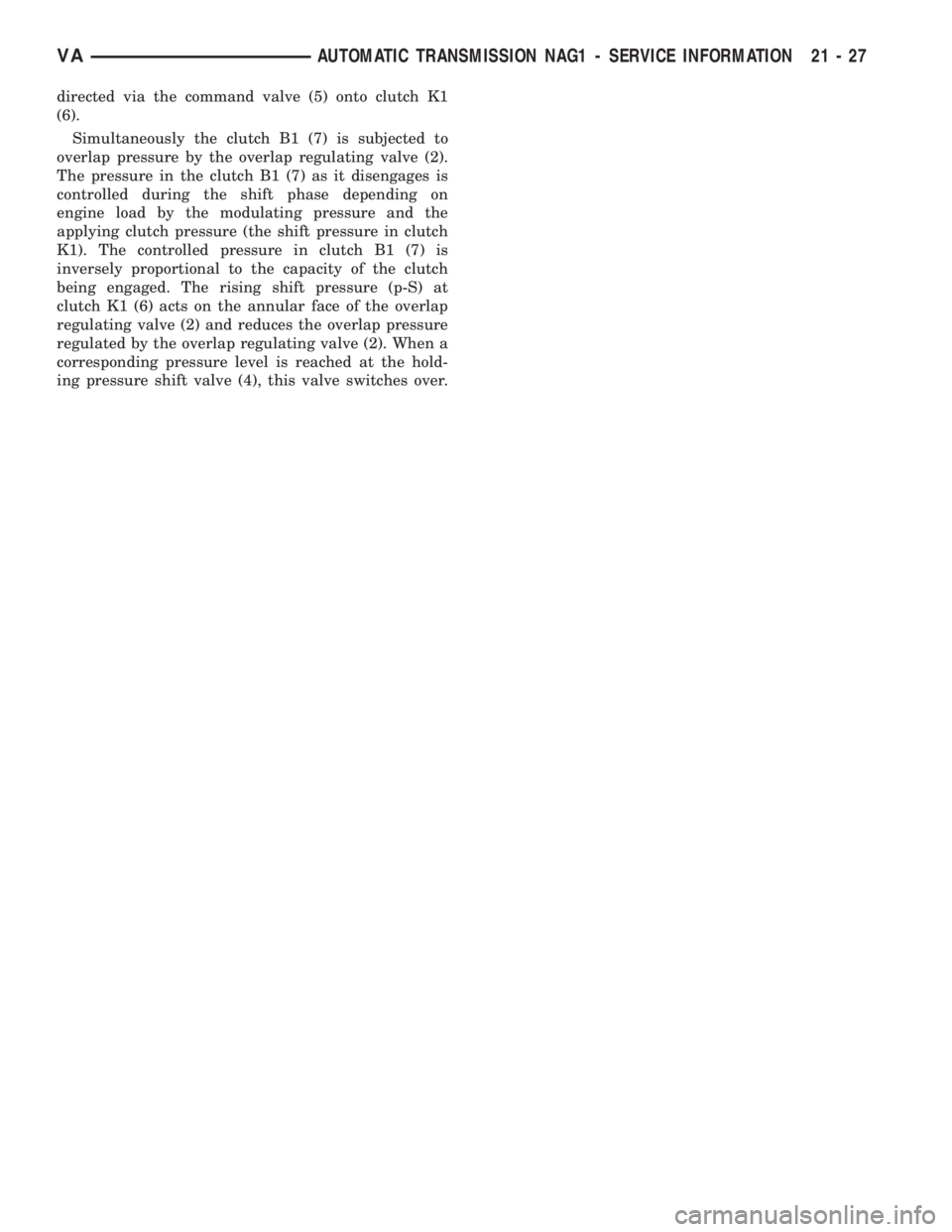
directed via the command valve (5) onto clutch K1
(6).
Simultaneously the clutch B1 (7) is subjected to
overlap pressure by the overlap regulating valve (2).
The pressure in the clutch B1 (7) as it disengages is
controlled during the shift phase depending on
engine load by the modulating pressure and the
applying clutch pressure (the shift pressure in clutch
K1). The controlled pressure in clutch B1 (7) is
inversely proportional to the capacity of the clutch
being engaged. The rising shift pressure (p-S) at
clutch K1 (6) acts on the annular face of the overlap
regulating valve (2) and reduces the overlap pressure
regulated by the overlap regulating valve (2). When a
corresponding pressure level is reached at the hold-
ing pressure shift valve (4), this valve switches over.
VAAUTOMATIC TRANSMISSION NAG1 - SERVICE INFORMATION 21 - 27
Page 1783 of 2305
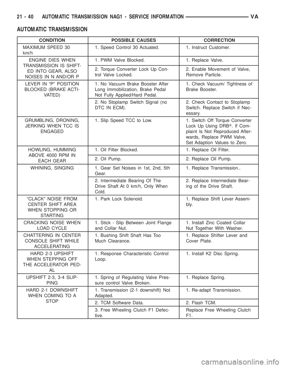
AUTOMATIC TRANSMISSION
CONDITION POSSIBLE CAUSES CORRECTION
MAXIMUM SPEED 30
km/h1. Speed Control 30 Actuated. 1. Instruct Customer.
ENGINE DIES WHEN
TRANSMISSION IS SHIFT-
ED INTO GEAR, ALSO
NOISES IN N AND/OR P1. PWM Valve Blocked. 1. Replace Valve.
2. Torque Converter Lock Up Con-
trol Valve Locked.2. Enable Movement of Valve,
Remove Particle.
LEVER IN ªPº POSITION
BLOCKED (BRAKE ACTI-
VATED)1. No Vacuum Brake Booster After
Long Immobilization, Brake Pedal
Not Fully Applied/Hard Pedal.1. Check Vacuum/ Tightness of
Brake Booster.
2. No Stoplamp Switch Signal (no
DTC IN ECM).2. Check Contact to Stoplamp
Switch. Replace Switch if Nec-
essary.
GRUMBLING, DRONING,
JERKING WHEN TCC IS
ENGAGED1. Slip Speed TCC to Low. 1. Switch Off Torque Converter
Lock Up Using DRBT. If Com-
plaint Is Not Reproduced After-
wards, Replace PWM Valve,
Set Adaption Values to Zero.
HOWLING, HUMMING
ABOVE 4000 RPM IN
EACH GEAR1. Oil Filter Blocked. 1. Replace Oil Filter.
2. Oil Pump. 2. Replace Oil Pump.
WHINING, SINGING 1. Gear Set Noises in 1st, 2nd, 5th
Gear.1. Replace Transmission..
2. Intermediate Bearing Of The
Drive Shaft At 0 km/h, Only When
Cold.2. Replace Intermediate Bear-
ing of the Drive Shaft.
9CLACKº NOISE FROM
CENTER SHIFT AREA
WHEN STOPPING OR
STARTING1. Park Lock Solenoid. 1. Replace Shift Lever Assem-
bly.
CRACKING NOISE WHEN
LOAD CYCLE1. Stick - Slip Between Joint Flange
and Collar Nut.1. Install Zinc Coated Collar
Nut Together With Washer.
CHATTERING IN CENTER
CONSOLE SHIFT WHILE
ACCELERATING1. Bushing Shift Shaft Has Too
Much Clearance.1. Replace Shifter Lever and
Cover Plate.
HARD 2-3 UPSHIFT
WHEN STEPPING OFF
THE ACCELERATOR PED-
AL1. Response Characteristic Control
Loop.1. Install K2 Disc Spring.
UPSHIFT 2-3, 3-4 SLIP-
PING1. Spring of Regulating Valve Pres-
sure control Valve Broken.1. Replace Spring.
HARD 2-1 DOWNSHIFT
WHEN COMING TO A
STOP1. Transmission (2-1 downshift) Not
Adapted.1. Re-adapt Transmission.
2. TCM Software Data. 2. Flash TCM.
3. Free Wheeling Clutch F1 Defec-
tive.Replace Free Wheeling Clutch
F1.
21 - 40 AUTOMATIC TRANSMISSION NAG1 - SERVICE INFORMATIONVA
Page 1784 of 2305
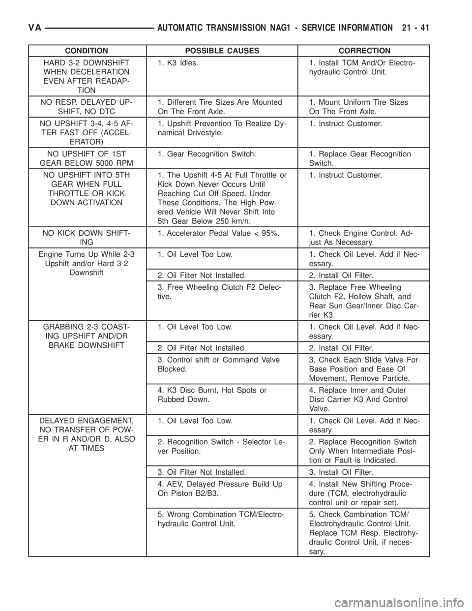
CONDITION POSSIBLE CAUSES CORRECTION
HARD 3-2 DOWNSHIFT
WHEN DECELERATION
EVEN AFTER READAP-
TION1. K3 Idles. 1. Install TCM And/Or Electro-
hydraulic Control Unit.
NO RESP. DELAYED UP-
SHIFT, NO DTC1. Different Tire Sizes Are Mounted
On The Front Axle.1. Mount Uniform Tire Sizes
On The Front Axle.
NO UPSHIFT 3-4, 4-5 AF-
TER FAST OFF (ACCEL-
ERATOR)1. Upshift Prevention To Realize Dy-
namical Drivestyle.1. Instruct Customer.
NO UPSHIFT OF 1ST
GEAR BELOW 5000 RPM1. Gear Recognition Switch. 1. Replace Gear Recognition
Switch.
NO UPSHIFT INTO 5TH
GEAR WHEN FULL
THROTTLE OR KICK
DOWN ACTIVATION1. The Upshift 4-5 At Full Throttle or
Kick Down Never Occurs Until
Reaching Cut Off Speed. Under
These Conditions, The High Pow-
ered Vehicle Will Never Shift Into
5th Gear Below 250 km/h.1. Instruct Customer.
NO KICK DOWN SHIFT-
ING1. Accelerator Pedal Value < 95%. 1. Check Engine Control. Ad-
just As Necessary.
Engine Turns Up While 2-3
Upshift and/or Hard 3-2
Downshift1. Oil Level Too Low. 1. Check Oil Level. Add if Nec-
essary.
2. Oil Filter Not Installed. 2. Install Oil Filter.
3. Free Wheeling Clutch F2 Defec-
tive.3. Replace Free Wheeling
Clutch F2, Hollow Shaft, and
Rear Sun Gear/Inner Disc Car-
rier K3.
GRABBING 2-3 COAST-
ING UPSHIFT AND/OR
BRAKE DOWNSHIFT1. Oil Level Too Low. 1. Check Oil Level. Add if Nec-
essary.
2. Oil Filter Not Installed. 2. Install Oil Filter.
3. Control shift or Command Valve
Blocked.3. Check Each Slide Valve For
Base Position and Ease Of
Movement, Remove Particle.
4. K3 Disc Burnt, Hot Spots or
Rubbed Down.4. Replace Inner and Outer
Disc Carrier K3 And Control
Valve.
DELAYED ENGAGEMENT,
NO TRANSFER OF POW-
ER IN R AND/OR D, ALSO
AT TIMES1. Oil Level Too Low. 1. Check Oil Level. Add if Nec-
essary.
2. Recognition Switch - Selector Le-
ver Position.2. Replace Recognition Switch
Only When Intermediate Posi-
tion or Fault is Indicated.
3. Oil Filter Not Installed. 3. Install Oil Filter.
4. AEV, Delayed Pressure Build Up
On Piston B2/B3.4. Install New Shifting Proce-
dure (TCM, electrohydraulic
control unit or repair set).
5. Wrong Combination TCM/Electro-
hydraulic Control Unit.5. Check Combination TCM/
Electrohydraulic Control Unit.
Replace TCM Resp. Electrohy-
draulic Control Unit, if neces-
sary.
VAAUTOMATIC TRANSMISSION NAG1 - SERVICE INFORMATION 21 - 41