2006 LAND ROVER FRELANDER 2 window
[x] Cancel search: windowPage 2592 of 3229
Publis hed: 11-May-2011
Side Panel Sheet Metal Repairs - Side PanelRemoval and Installation
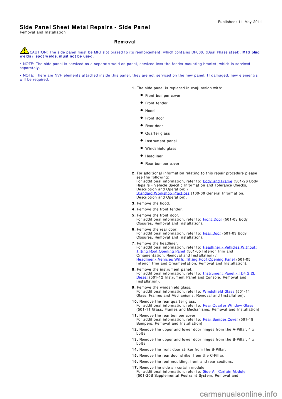
Removal
CAUTION: The side panel must be MIG slot brazed to its reinforcement, which contains DP600, (Dual Phase steel). MIG plug
w e lds / spot w e lds, must not be use d.
• NOTE: The side panel is serviced as a separate weld on panel, serviced less the fender mounting bracket, which is serviced
separately.
• NOTE: There are NVH elements attached inside this panel, they are not serviced on the new panel. If damaged, new element/s
will be required.
1. The s ide panel is replaced in conjunct ion wit h:
Front bumper cover
Front fender
Hood
Front door
Rear door
Quarter glass
Instrument panel
Windshield glass
Headliner
Rear bumper cover
2. For additional information relating to this repair procedure please
see the following:
Fo r a d d i t i o na l i nf o rma t i o n, re f e r t o : Body and Frame
(501-26 Body
Repairs - Vehicle Specific Information and Tolerance Checks,
Description and Operation) /
St a nd a rd W o rks ho p P ra ct i ce s
(100-00 General Informat ion,
Description and Operation).
3. Remove t he hood.
4. Remove the front fender.
5. Remove the front door.
Fo r a d d i t i o na l i nf o rma t i o n, re f e r t o : Front Door
(501-03 Body
Closures, Removal and Installation).
6. Remove t he rear door.
Fo r a d d i t i o na l i nf o rma t i o n, re f e r t o : Rear Door
(501-03 Body
Closures, Removal and Installation).
7. Remove the headliner.
Fo r a d d i t i o na l i nf o rma t i o n, re f e r t o : Headliner - Vehicles Without:
Tilting Roof Opening Panel (501-05 Int eri or Tri m and
Ornamentat ion, Removal and Inst all at ion) /
Headliner - Vehicles With: Tilting Roof Opening Panel
(501-05
Interior Trim and Ornamentation, Removal and Installation).
8. Re mo ve t he i ns t rume nt pa ne l .
Fo r a d d i t i o na l i nf o rma t i o n, re f e r t o : Inst rument Panel - TD4 2.2L
Di es e l (501-12 Inst rument Panel and Cons ole, Removal and
Installation).
9. Remove the windshield glass.
Fo r a d d i t i o na l i nf o rma t i o n, re f e r t o : Windshield Glass
(501-11
Glass, Frames and Mechanisms, Removal and Installation).
10. Remove the rear quarter glass.
Fo r a d d i t i o na l i nf o rma t i o n, re f e r t o : Rear Quarter Window Glass
(501-11 Glass, Frames and Mechanisms, Removal and Installation).
11. Re move t he re a r bumpe r co ve r.
Fo r a d d i t i o na l i nf o rma t i o n, re f e r t o : Rear Bumper Cover
(501-19
Bumpe rs , Re mo va l a nd I ns t a l l a t i o n).
12. Remove the upper and lower door hinges from the A-Pillar, 4 x
bolts.
13. Remove the upper and lower door hinges from the B-Pillar, 4 x
bolts.
14. Remove the front door striker from the B-Pillar.
15. Remove the rear door striker from the C-Pillar.
16. Remove the roof moulding, front and rear sect ions .
17. Re mo ve t he s i d e a i r curt a i n mo d ul e .
Fo r a d d i t i o na l i nf o rma t i o n, re f e r t o : Si d e A i r Curt a i n Mo d ul e
(501-20B Supplement al Res t raint Syst em, Removal and
Page 2636 of 3229
Publ is hed: 11-May-2011
Rear End Sheet Metal Repairs - Quarter Panel
Removal and Installation
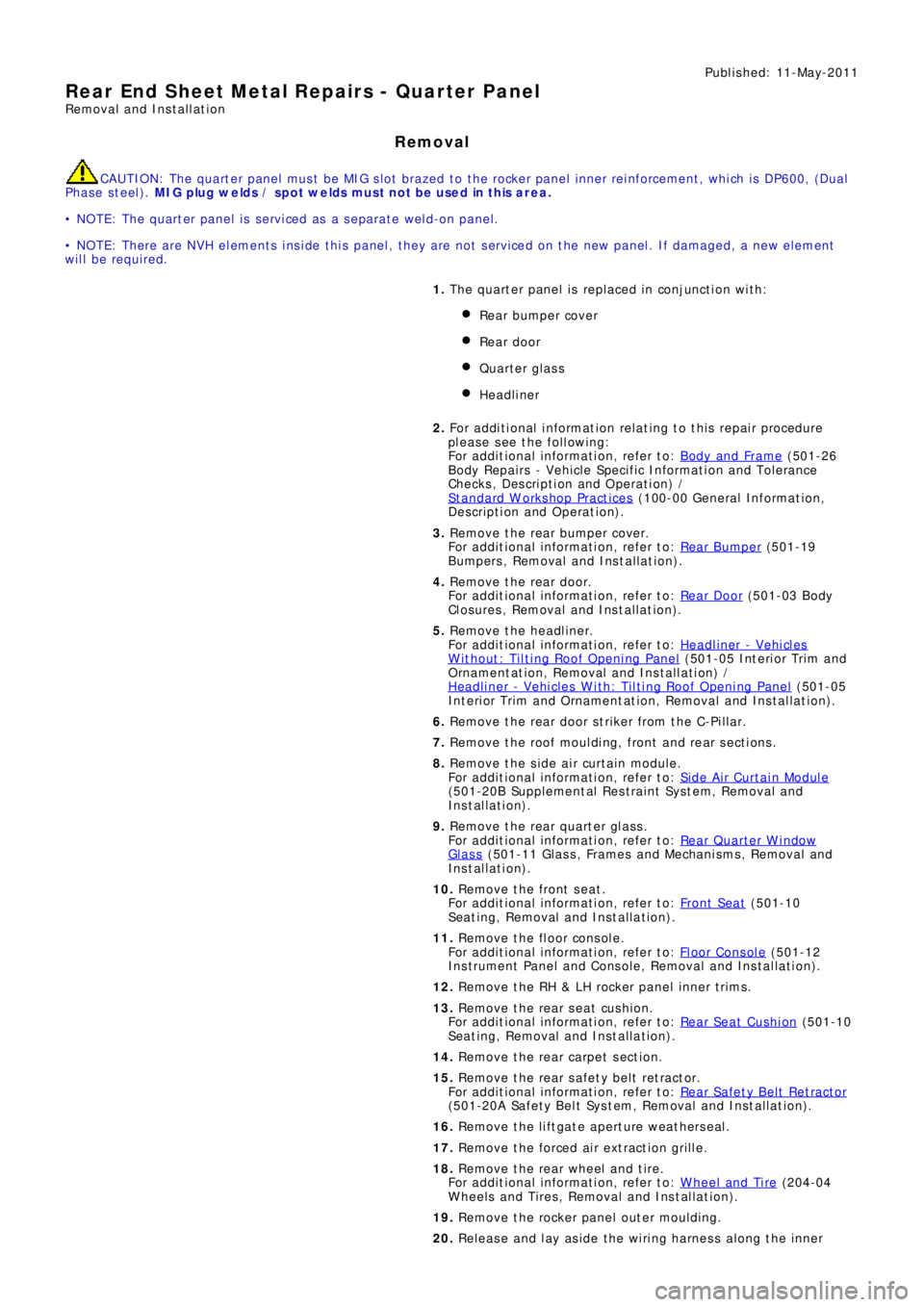
Removal
CAUTION: The quarter panel must be MIG slot brazed to the rocker panel inner reinforcement, which is DP600, (Dual
Phase steel). MIG plug we lds / spot w elds must not be use d in this are a.
• NOTE: The quarter panel is serviced as a separate weld-on panel.
• NOTE: There are NVH elements inside this panel, they are not serviced on the new panel. If damaged, a new element
will be required.
1. The quarter panel is replaced in conjunction with:
Rear bumper cover
Rear door
Quarter glass
Headliner
2. Fo r a d d i t i o na l i nf o rma t i o n re l a t i ng t o t hi s re p a i r p ro ce d ure
please see the following:
Fo r a d d i t i o na l i nf o rma t i o n, re f e r t o : Body and Frame
(501-26
Body Repairs - Vehicle Specific Information and Tolerance
Checks, Description and Operation) /
St a nd a rd W o rks ho p P ra ct i ce s
(100-00 Ge ne ra l I nf o rma t i o n,
Description and Operation).
3. Re move t he re a r bumpe r co ve r.
Fo r a d d i t i o na l i nf o rma t i o n, re f e r t o : Rear Bumper
(501-19
Bumpe rs , Re mo va l a nd Ins t a l l a t i on).
4. Remove the rear door.
Fo r a d d i t i o na l i nf o rma t i o n, re f e r t o : Rear Door
(501-03 Body
Closures, Removal and Installation).
5. Remove the headliner.
Fo r a d d i t i o na l i nf o rma t i o n, re f e r t o : Headliner - Vehicles
Without: Tilting Roof Opening Panel (501-05 Int eri or Tri m and
Ornamentation, Removal and Installation) /
Headliner - Vehicles With: Tilting Roof Opening Panel
(501-05
Int erior Trim and Ornamentat ion, Removal and Installat ion).
6. Re mo ve t he re a r d o o r s t ri ke r f ro m t he C-P i l l a r.
7. Remove the roof moulding, front and rear sections.
8. Re mo ve t he s i d e a i r curt a i n mo d ul e .
Fo r a d d i t i o na l i nf o rma t i o n, re f e r t o : Si d e A i r Curt a i n Mo d ul e
(501-20B Suppl ement al Res t rai nt Sys t em, Removal and
Installation).
9. Remove the rear quarter glass.
Fo r a d d i t i o na l i nf o rma t i o n, re f e r t o : Rear Quarter Window
Gl a s s (501-11 Glass, Frames and Mechanisms, Removal and
Installation).
10. Remove the front seat.
Fo r a d d i t i o na l i nf o rma t i o n, re f e r t o : Front Seat
(501-10
Seating, Removal and Installation).
11. Remove the floor console.
Fo r a d d i t i o na l i nf o rma t i o n, re f e r t o : Floor Console
(501-12
Instrument Panel and Console, Removal and Installation).
12. Remove the RH & LH rocker panel inner trims.
13. Remove the rear seat cushion.
Fo r a d d i t i o na l i nf o rma t i o n, re f e r t o : Rear Seat Cushion
(501-10
Seating, Removal and Installation).
14. Re mo ve t he re a r ca rp e t s e ct i o n.
15. Remove the rear safety belt retractor.
Fo r a d d i t i o na l i nf o rma t i o n, re f e r t o : Rear Safety Belt Retractor
(501-20A Safe t y Bel t Sys t em, Removal and Ins t al l at i on).
16. Remove the liftgate aperture weatherseal.
17. Remove the forced air extraction grille.
18. Remove the rear wheel and tire.
Fo r a d d i t i o na l i nf o rma t i o n, re f e r t o : Wheel and Tire
(204-04
Wheels and Tires, Removal and Installation).
19. Remove the rocker panel outer moulding.
20. Release and lay aside the wiring harness along the inner
Page 2664 of 3229
Publ is hed: 11-May-2011
Rear End Sheet Metal Repairs - Rear Lamp Mounting Panel
Removal and Installation
Removal
• NOTE: The rear lamp mounting panel is serviced as a separate weld-on panel.
• NOTE: There are NVH elements attached to the old panel, they are not serviced on the new panel. If damaged, new
elements will be required.
1. The rear lamp mounting panel is replaced in conjunction with:
Rear bumper cover
Re a r bumpe r a rma t ure
2. Fo r a d d i t i o na l i nf o rma t i o n re l a t i ng t o t hi s re p a i r p ro ce d ure
please see the following:
Fo r a d d i t i o na l i nf o rma t i o n, re f e r t o : Body and Frame
(501-26
Body Repairs - Vehicle Specific Information and Tolerance
Checks, Description and Operation) /
St a nd a rd W o rks ho p P ra ct i ce s
(100-00 Ge ne ra l I nf o rma t i o n,
Description and Operation).
3. Re move t he re a r bumpe r.
Fo r a d d i t i o na l i nf o rma t i o n, re f e r t o : Rear Bumper
(501-19
Bumpe rs , Re mo va l a nd Ins t a l l a t i on).
4. Disconnect both battery cables.
5. Remove the D-Pillar trim panel.
Fo r a d d i t i o na l i nf o rma t i o n, re f e r t o : D-Pillar Trim Panel
(501-05
Int erior Trim and Ornamentat ion, Removal and Installat ion).
6. Re mo ve t he re a r w he e l a nd t i re .
7. Remove t he rear quart er window moulding.
8. Remove the loadspace trim panel.
9. Remove the forced air extraction grille.
10. Release the insulating material and lay aside.
11. Release and lay aside the wiring harness.
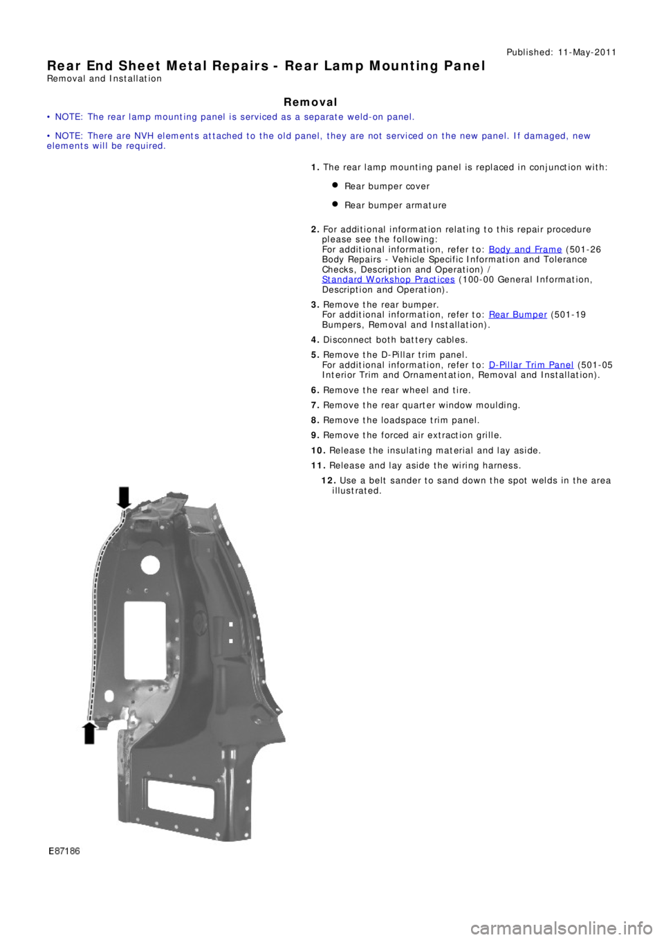
12. Use a belt sander to sand down the spot welds in the area
illustrated.
Page 2723 of 3229

Contents
3
R
Quick start
QUICK START ................................................... 7
Filling station information
FILLING STATION INFORMATION................... 33
Introduction
SYMBOLS GLOSSARY .................................... 35
LABEL LOCATIONS ......................................... 35
HEALTH AND SAFETY ..................................... 36
DATA RECORDING.......................................... 37
DISABILITY MODIFICATIONS ......................... 37
PARTS AND ACCESSORIES ............................ 37
Keys and remote controls
USING THE KEY .............................................. 40
GENERAL INFORMATION ON RADIO
FREQUENCIES ................................................ 40
USING THE REMOTE CONTROL ..................... 41
Locks
LOCKING AND UNLOCKING ............................ 44
Alarm
ARMING THE ALARM ..................................... 45
DISARMING THE ALARM ............................... 46
Seats
SITTING IN THE CORRECT POSITION ............ 47
MANUAL SEATS ............................................. 48
ELECTRIC SEATS ............................................ 49
HEAD RESTRAINTS ........................................ 51
REAR SEATS................................................... 51
HEATED SEATS............................................... 53
Seat belts
PRINCIPLE OF OPERATION ............................ 54
SEAT BELT REMINDER ................................... 55
FASTENING THE SEAT BELTS ........................ 56
SEAT BELT HEIGHT ADJUSTMENT................. 56
USING SEAT BELTS DURI NG PREGNANCY .... 57
Supplementary restraints system
PRINCIPLE OF OPERATION ............................ 58
AIRBAG WARNING LAMP ............................... 61
DISABLING THE PASSENGER AIRBAG ........... 62
AIRBAG SERVICE INFORMATION ................... 63
Child safety
CHILD SEATS ................................................. 64
BOOSTER CUSHIONS ..................................... 66
ISOFIX ANCHOR POINTS................................ 67
CHILD SAFETY LOCKS ................................... 69
Steering wheel
ADJUSTING THE STEERING WHEEL .............. 70
AUDIO CONTROL ........................................... 70
Lighting
LIGHTING CONTROL ...................................... 72
FRONT FOG LAMPS........................................ 72
REAR FOG LAMPS.......................................... 73
ADJUSTING THE HEADLAMPS....................... 73
HEADLAMP LEVELLING ................................. 73
HAZARD WARNING FLASHERS...................... 74
ADAPTIVE FRONT LIGHTING SYSTEM (AFS) . 74
DIRECTION INDICATORS ............................... 75
INTERIOR LAMPS .......................................... 76
APPROACH LAMPS ........................................ 76
CHANGING A BULB ........................................ 77
BULB SPECIFICATION CHART ........................ 86
Wipers and washers
WINDSCREEN WIPERS .................................. 87
RAIN SENSOR ................................................ 87
WINDSCREEN WASHERS............................... 88
HEADLAMP WASHERS................................... 88
REAR WINDOW WIPER AND WASHERS ........ 89
ADJUSTING THE WINDSCREEN WASHER JETS .
89
CHECKING THE WIPER BLADES .................... 90
CHANGING THE WIPER BLADES.................... 90
Windows and mirrors
ELECTRIC WINDOWS ..................................... 93
EXTERIOR MIRRORS ..................................... 94
ELECTRIC EXTERIOR MIRRORS .................... 95
INTERIOR MIRROR ........................................ 96
Instruments
INSTRUMENT PANEL OVERVIEW .................. 97
Information displays
TRIP COMPUTER ........................................... 99
INFORMATION MESSAGES ............................ 99
Page 2724 of 3229

Contents
4
L
Climate control
AIR VENTS ................................................... 101
MANUAL CLIMATE CONTROL ...................... 102
AUTOMATIC CLIMATE CONTROL ................. 103
HEATED WINDOWS AND MIRRORS ............ 104
AUXILIARY HEATER ..................................... 104
ELECTRIC SUNROOF .................................... 105
Convenience features
SUN VISORS ................................................ 107
CLOCK .......................................................... 107
CIGAR LIGHTER ........................................... 109
ASHTRAY ..................................................... 109
AUXILIARY POWER SOCKETS ..................... 110
CUP HOLDERS ............................................. 111
STORAGE COMPARTMENTS ........................ 112
Starting the engine
GENERAL INFORMATION ............................. 113
STARTING A PETROL ENGINE ..................... 114
STARTING A DIESEL ENGINE ....................... 115
DIESEL PARTICULATE FILTER (DPF) ........... 116
Transmission
MANUAL TRANSMISSION ............................ 118
AUTOMATIC TRANSMISSION ...................... 118
TECHNICAL SPECIFICATIONS ...................... 122
Brakes
PRINCIPLE OF OPERATION .......................... 123
HINTS ON DRIVING WITH ABS .................... 123
PARKING BRAKE .......................................... 124
Parking aid
PRINCIPLE OF OPERATION .......................... 126
USING THE PARKING AID ............................ 127
Driving hints
GENERAL DRIVING POINTS ......................... 128
REDUCED ENGINE PERFORMANCE ............. 128
RUNNING-IN ................................................ 128
ECONOMICAL DRIVING ................................ 129
Cruise control
PRINCIPLE OF OPERATION .......................... 130
USING CRUISE CONTROL ............................ 130
Terrain response
PRINCIPLE OF OPERATION .......................... 132
USING TERRAIN RESPONSE ........................ 132
Hill descent control (HDC)
PRINCIPLE OF OPERATION .......................... 136
USING HDC ................................................... 137
Traction control
USING TRACTION CONTROL ........................ 139
Stability control
PRINCIPLE OF OPERATION .......................... 140
USING STABILITY CONTROL ........................ 141
Fuel and refuelling
SAFETY PRECAUTIONS................................. 142
FUEL QUALITY .............................................. 142
RUNNING OUT OF FUEL................................ 144
FUEL CUT-OFF............................................... 144
FUEL FILLER FLAP ........................................ 144
REFUELLING ................................................. 145
TECHNICAL SPECIFICATIONS ....................... 146
Load carrying
GENERAL INFORMATION.............................. 147
LUGGAGE ANCHOR POINTS ......................... 148
LUGGAGE COVERS ....................................... 149
Towing
TOWING A TRAILER...................................... 150
LEVELLING.................................................... 151
ESSENTIAL TOWING CHECKS ...................... 151
RECOMMENDED TOWING WEIGHTS ............ 152
TOW BAR ...................................................... 153
Vehicle care
CLEANING THE ALLOY WHEELS................... 154
CLEANING THE EXTERIOR ............................ 154
CLEANING THE INTERIOR ............................ 155
REPAIRING MINOR PAINT DAMAGE ............ 156
Maintenance
GENERAL INFORMATION.............................. 157
OPENING AND CLOSING THE BONNET......... 160
ENGINE COMPARTMENT OVERVIEW ........... 161
ENGINE OIL CHECK....................................... 162
Page 2727 of 3229
7
Quick start
R
Quick startQUICK START
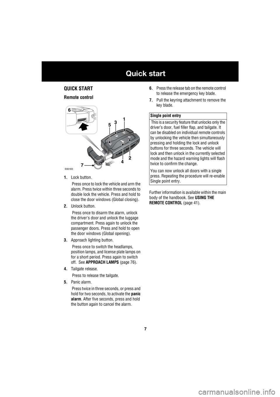
Remote control
1. Lock button.
Press once to lock the vehicle and arm the
alarm. Press twice within three seconds to
double lock the vehicle. Press and hold to
close the door windows (Global closing).
2. Unlock button.
Press once to disarm the alarm, unlock
the driver's door and unlock the luggage
compartment. Press again to unlock the
passenger doors. Press and hold to open
the door windows (Global opening).
3. Approach lighting button.
Press once to switch the headlamps,
position lamps, and license plate lamps on
for a short period. Press again to switch
off. See APPROACH LAMPS (page 76).
4. Tailgate release.
Press to release the tailgate.
5. Panic alarm.
Press twice in three seconds, or press and
hold for two seconds, to activate the panic
alarm . After five seconds, press and hold
the button again to cancel the alarm. 6.
Press the release tab on the remote control
to release the emergency key blade.
7. Pull the keyring attachment to remove the
key blade.
Further information is available within the main
body of the handbook. See USING THE
REMOTE CONTROL (page 41).
6
31
E83183
2
74
5
Single point entry
This is a security feature that unlocks only the
driver’s door, fuel fille r flap, and tailgate. It
can be disabled on indi vidual remote controls
by unlocking the vehicle then simultaneously
pressing and holding th e lock and unlock
buttons for three sec onds. The vehicle will
lock and then unlock in the currently selected
mode and the hazard wa rning lights will flash
twice to confirm the change.
You can now unlock all doors with a single
press. Repeating the pr ocedure will re-enable
Single point entry.
Page 2730 of 3229
10
Quick start
L
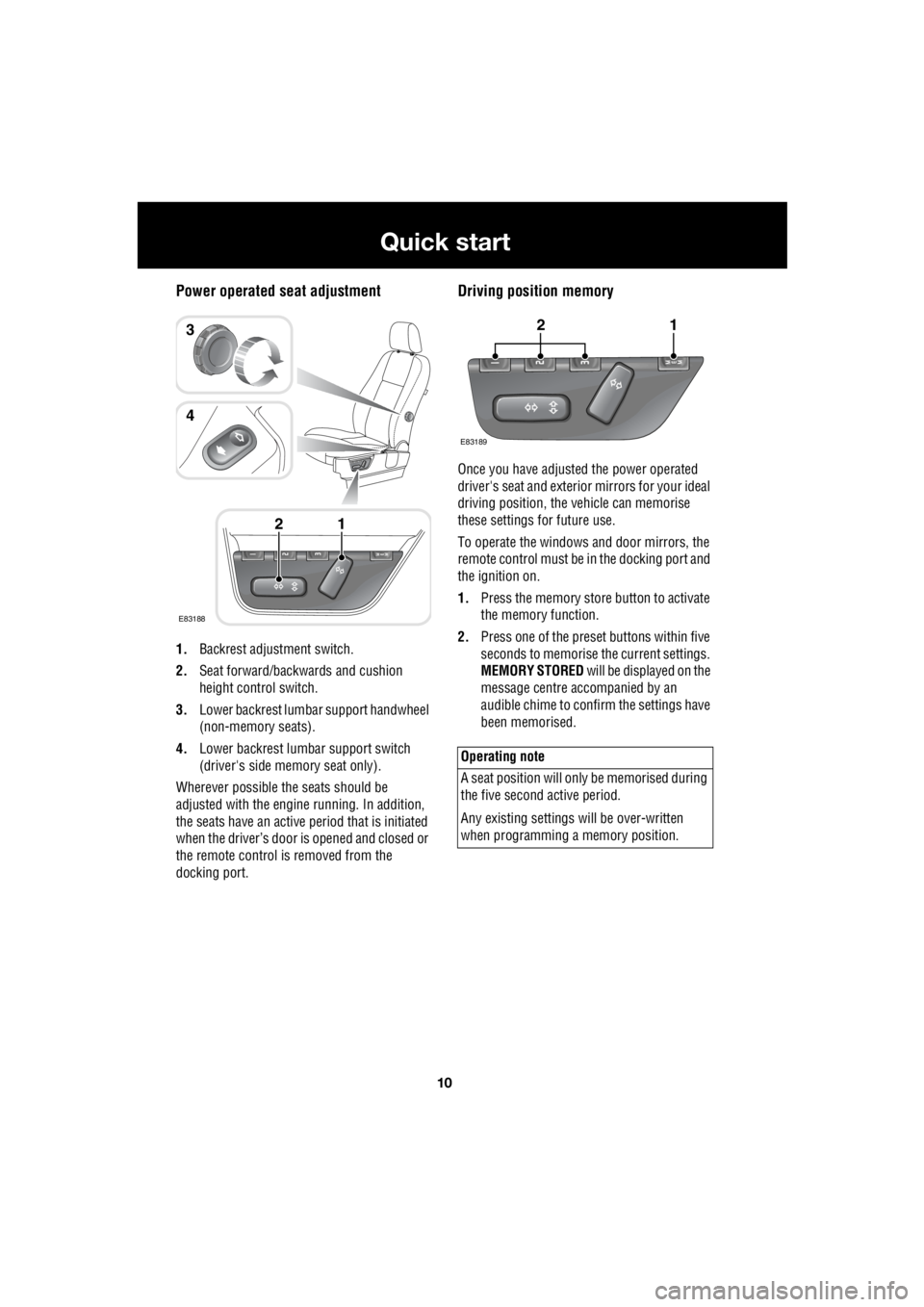
Power operated seat adjustment
1. Backrest adjustment switch.
2. Seat forward/backwards and cushion
height control switch.
3. Lower backrest lumbar support handwheel
(non-memory seats).
4. Lower backrest lumbar support switch
(driver's side memory seat only).
Wherever possible the seats should be
adjusted with the engine running. In addition,
the seats have an active period that is initiated
when the driver’s door is opened and closed or
the remote control is removed from the
docking port.
Driving position memory
Once you have adjusted the power operated
driver's seat and exterior mirrors for your ideal
driving position, the vehicle can memorise
these settings for future use.
To operate the windows and door mirrors, the
remote control must be in the docking port and
the ignition on.
1. Press the memory store button to activate
the memory function.
2. Press one of the preset buttons within five
seconds to memorise the current settings.
MEMORY STORED will be displayed on the
message centre accompanied by an
audible chime to confirm the settings have
been memorised.
E83188
12
3
4
Operating note
A seat position will onl y be memorised during
the five second active period.
Any existing settings w ill be over-written
when programming a memory position.
E83189
12
Page 2731 of 3229
11
Quick start
R
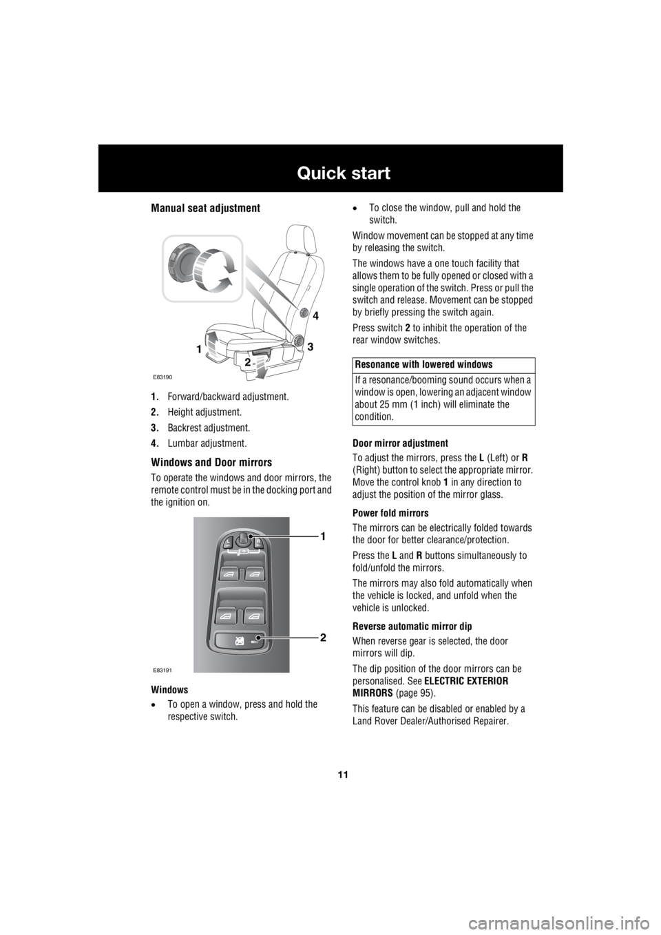
Manual seat adjustment
1. Forward/backward adjustment.
2. Height adjustment.
3. Backrest adjustment.
4. Lumbar adjustment.
Windows and Door mirrors
To operate the windows and door mirrors, the
remote control must be in the docking port and
the ignition on.
Windows
• To open a window, press and hold the
respective switch. •
To close the window, pull and hold the
switch.
Window movement can be stopped at any time
by releasing the switch.
The windows have a one touch facility that
allows them to be fully opened or closed with a
single operation of the switch. Press or pull the
switch and release. Mo vement can be stopped
by briefly pressing the switch again.
Press switch 2 to inhibit the operation of the
rear window switches.
Door mirror adjustment
To adjust the mirrors, press the L (Left) or R
(Right) button to select the appropriate mirror.
Move the control knob 1 in any direction to
adjust the position of the mirror glass.
Power fold mirrors
The mirrors can be electr ically folded towards
the door for better clearance/protection.
Press the L and R buttons simultaneously to
fold/unfold the mirrors.
The mirrors may also fold automatically when
the vehicle is locked, and unfold when the
vehicle is unlocked.
Reverse automatic mirror dip
When reverse gear is selected, the door
mirrors will dip.
The dip position of the door mirrors can be
personalised. See ELECTRIC EXTERIOR
MIRRORS (page 95).
This feature can be disabled or enabled by a
Land Rover Dealer/A uthorised Repairer.
3
2
1
E83190
4
1
2
E83191
Resonance with lowered windows
If a resonance/booming sound occurs when a
window is open, lowering an adjacent window
about 25 mm (1 inch) will eliminate the
condition.