Page 1606 of 3229
Remove t he nut and bol t securi ng the fuel tank
fill er pipe t o t he body.
T orque: 10 Nm Loosen t he fuel t ank fi ll er pi pe lower bracket .
T orque: 10 Nm Loosen t he cli p and dis connect the fuel fi ller
hos e from t he fuel t ank. Loosen t he cli p and dis connect fuel fi ll er pi pe
vent hos e. 6.
T orque:
10 Nm 7.
Installation To i nst all , revers e t he removal procedure.
1.
Page 1607 of 3229
Publi s hed: 11-May-2011
Fuel Tank and Lines - TD4 2.2L Diesel - Fuel Filter
Removal and Inst all ati on
Removal
• W ARNINGS: W ai t for a mini mum of 1 minute aft er the engine has s t opped before carryi ng out any
repair t o t he fuel inject ion
s ys t em. Avoid flames , s parks or li ght ed s ubs t ances .
Be prepared t o col lect escaping fuel .
Di sconnect t he bat t ery ground cable.
Refer t o: Specificati ons (414-00 Bat tery and Charging Sys tem -
General Informat ion, Specificati ons).
1.
Remove t he engi ne cover.
Refer t o: Engi ne Cover - TD4 2.2L Dies el (501-05 Interior Tri m and
Ornament ati on, Removal and Ins tal lat ion).
2. 3.
T orque:
9 Nm 4.
Page 1609 of 3229
Publi s hed: 11-May-2011
Fuel Tank and Lines - TD4 2.2L Diesel - Fuel Pump and Sender Unit
Removal and Inst all ati on
Removal
• NOTE: Removal s t eps in t his procedure may cont ain i nst all ati on det ail s.
Di sconnect t he bat t ery ground cable.
Refer t o: Specificati ons (414-00 Bat tery and Charging Sys tem -General Informat ion, Specificati ons).
1.
Remove t he fuel fi lt er.
Refer t o: Fuel Fil ter (310-01B Fuel Tank and Lines - TD4 2.2L Dies el ,Removal and Ins tall ati on).
2.
3. CAUTION: Extreme cleanli nes s mus t beexercis ed when handl ing t hese components .3.
Installation
To i nst all , revers e t he removal procedure.1.
Page 1849 of 3229
Publi s hed: 11-May-2011
Generator and Regulator - GeneratorTD4 2.2L Diesel
Removal and Inst all ati on
Removal
Remove t he cover and dis connect the bat tery ground cabl e.
Refer t o: Specificati ons (414-00 Bat tery and Charging Sys tem -
General Informat ion, Specificati ons).
1.
Remove t he fuel fi lt er.
Refer t o: Fuel Fil ter (310-01B Fuel Tank and Lines - TD4 2.2L Dies el ,
Removal and Ins tall ati on).
2.
3. W ARNING: Make sure t o s upport the vehicle wit h axle
s tands .
Rais e and s upport t he vehi cl e.
3.
Remove t he engi ne undershi eld.
Refer t o: Engi ne Unders hi eld (501-02 Front End Body Panel s ,
Removal and Ins tall ati on).
4.
Remove t he acces sory dri ve bel t.
Refer t o: Acces sory Dri ve Belt (303-05B Acces sory Drive - TD4 2.2L
Di es el, Removal and Ins tal lat ion).
5. 6.
7.
Page 1853 of 3229

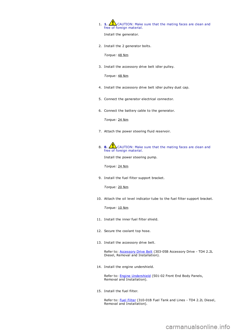
1. CAUTION: Make s ure that the mati ng faces are cl ean and
free of foreign mat eri al.
Inst all t he generat or.
1.
Inst all t he 2 generator bolt s .
T orque: 48 Nm 2.
Inst all t he acces sory dri ve bel t idl er pull ey.
T orque: 48 Nm 3.
Inst all t he acces sory dri ve bel t idl er pull ey dust cap.
4.
Connect t he generator electrical connect or.
5.
Connect t he batt ery cable t o t he generator.
T orque: 24 Nm 6.
At tach t he power s t eering flui d res ervoir.
7.
8. CAUTION: Make s ure that the mati ng faces are cl ean and
free of foreign mat eri al.
Inst all t he power s t eering pump.
T orque: 24 Nm 8.
Inst all t he fuel fi lt er support bracket.
T orque: 20 Nm 9.
At tach t he oil level indicator t ube to the fuel fil ter s upport bracket .
T orque: 10 Nm 10.
Inst all t he inner fuel fi lt er shi el d.
11.
Secure t he cool ant t op hos e.
12.
Inst all t he acces sory dri ve bel t.
Refer t o: Acces sory Dri ve Belt (303-05B Acces sory Drive - TD4 2.2L
Di es el, Removal and Ins tal lat ion).
13.
Inst all t he engi ne undershi eld.
Refer t o: Engi ne Unders hi eld (501-02 Front End Body Panel s ,
Removal and Ins tall ati on).
14.
Inst all t he fuel fi lt er.
Refer t o: Fuel Fil ter (310-01B Fuel Tank and Lines - TD4 2.2L Dies el ,
Removal and Ins tall ati on).
15.
Page 2035 of 3229

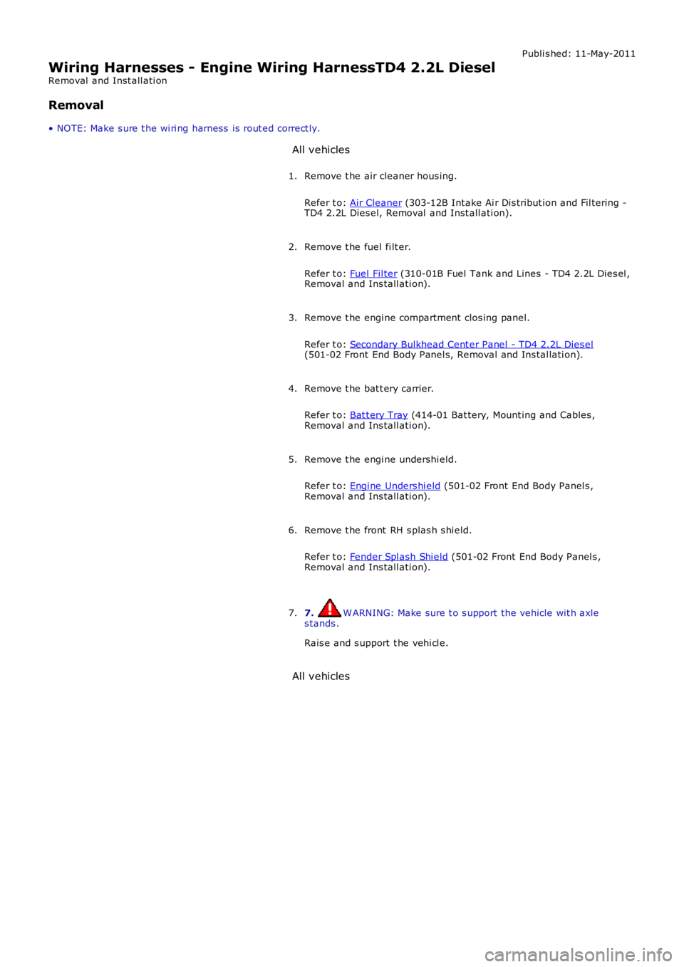
Publi s hed: 11-May-2011
Wiring Harnesses - Engine Wiring HarnessTD4 2.2L Diesel
Removal and Inst all ati on
Removal
• NOTE: Make s ure t he wi ri ng harness is rout ed correct ly. All vehicles
Remove t he air cleaner hous ing.
Refer t o: Air Cleaner (303-12B Intake Ai r Dis tribut ion and Fil tering -
TD4 2.2L Dies el, Removal and Inst all ati on).
1.
Remove t he fuel fi lt er.
Refer t o: Fuel Fil ter (310-01B Fuel Tank and Lines - TD4 2.2L Dies el ,
Removal and Ins tall ati on).
2.
Remove t he engi ne compartment clos ing panel.
Refer t o: Secondary Bulkhead Cent er Panel - TD4 2.2L Dies el (501-02 Front End Body Panel s, Removal and Ins tal lati on).
3.
Remove t he bat t ery carrier.
Refer t o: Bat t ery Tray (414-01 Bat tery, Mount ing and Cables ,
Removal and Ins tall ati on).
4.
Remove t he engi ne undershi eld.
Refer t o: Engi ne Unders hi eld (501-02 Front End Body Panel s ,
Removal and Ins tall ati on).
5.
Remove t he front RH s plas h s hi eld.
Refer t o: Fender Spl ash Shi eld (501-02 Front End Body Panel s ,
Removal and Ins tall ati on).
6.
7. W ARNING: Make sure t o s upport the vehicle wit h axle
s tands .
Rais e and s upport t he vehi cl e.
7.
All vehicles
Page 2593 of 3229

Installation).
18. Remove the front seat.
Fo r a d d i t i o na l i nf o rma t i o n, re f e r t o : Front Seat
(501-10 Seat ing,
Removal and Installation).
19. Remove the floor console.
Fo r a d d i t i o na l i nf o rma t i o n, re f e r t o : Fl oor Cons ol e
(501-12
Instrument Panel and Console, Removal and Installation).
20. Remove the RH & LH rocker panel inner trims.
21. Remove the rear seat cushion.
Fo r a d d i t i o na l i nf o rma t i o n, re f e r t o : Rear Seat Cushion
(501-10
Seating, Removal and Installation).
22. Re mo ve t he re a r ca rp e t s e ct i o n.
23. Remove the B-Pillar side impact sensor.
Fo r a d d i t i o na l i nf o rma t i o n, re f e r t o : B-Pillar Side Impact Sensor
(501-20B Supplement al Res t raint Syst em, Removal and
Installation).
24. Remove the front safety belt retractor.
Fo r a d d i t i o na l i nf o rma t i o n, re f e r t o : Front Safety Belt Retractor
(501-20A Safet y Belt Sys t em, Removal and Ins t al lat ion).
25. Remove the rear safety belt retractor.
Fo r a d d i t i o na l i nf o rma t i o n, re f e r t o : Rear Safety Belt Retractor
(501-20A Safet y Belt Sys t em, Removal and Ins t al lat ion).
26. Release and lay aside the front carpet section.
27. Re mo ve t he re a r ca rp e t s e ct i o n.
28. Remove the front wheel and tire. LINK
29. Remove the rear wheel and tire.
Fo r a d d i t i o na l i nf o rma t i o n, re f e r t o : Wheel and Tire
(204-04
Wheels and Tires, Removal and Installation).
30. Remove the rocker panel out er mouldi ng.
31. Remove the liftgate aperture weatherseal.
32. Remove the forced air extraction grille.
33. Release and lay aside the insulating material at the inner
bulkhead.
34. Release and lay aside the insulating material at the inner quarter
panel.
35. Release and lay aside the wiring harnesses at the A-Pillar,
B-Pillar and rocker panel.
36. Release and lay aside the wiring harness along the inner quarter
panel and back panel.
37. Release and lay aside the insulating material at the inner quarter
panel.
38. RH side: Drain the fuel tank.
Fo r a d d i t i o na l i nf o rma t i o n, re f e r t o : Fuel Tank Draining
(310-00
Fuel Sys t em - General Informat ion, General Procedures).
39. RH side: Remove the fuel tank filler pipe.
Fo r a d d i t i o na l i nf o rma t i o n, re f e r t o : Fuel Tank Filler Pipe
(310-01A
Fuel Tank and Lines - I6 3.2L Petrol, Removal and Installation).
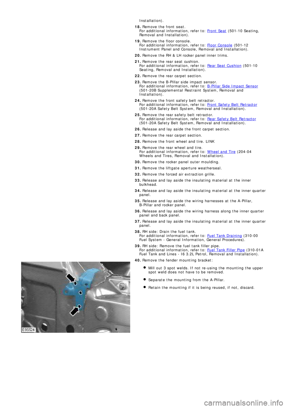
40. Remove the fender mounting bracket:
Mill out 3 spot welds. If not re-using the mounting the upper
spot weld does not have to be removed.
Separate the mounting from the A-Pillar.
Retain the mounting if it is being reused, if not, discard.
Page 2634 of 3229

Ite m De scr iption
19 Inner quart er panel and wheelhous e
20 Re a r bumpe r mount i ng
21 Li ft gat e
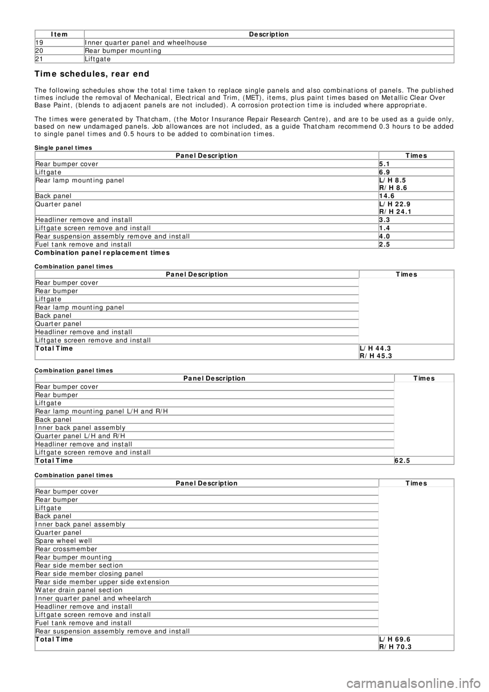
Time schedules, rear end
The following schedules show the total time taken to replace single panels and also combinations of panels. The published
times include the removal of Mechanical, Electrical and Trim, (MET), items, plus paint times based on Metallic Clear Over
Base Paint, (blends to adjacent panels are not included). A corrosion protection time is included where appropriate.
The times were generated by Thatcham, (the Motor Insurance Repair Research Centre), and are to be used as a guide only,
based on new undamaged panels. Job allowances are not included, as a guide Thatcham recommend 0.3 hours to be added
to single panel times and 0.5 hours to be added to combination times.
Single panel timesP a n e l D e s c r ip t io n T ime s
Rear bumper cover5.1
Liftgate6.9
Rear l amp mount ing panelL/H 8.5
R/H 8.6
Back panel14.6
Quarter panelL/H 22.9
R/H 24.1
Headliner remove and install3.3
Liftgate screen remove and install1.4
Rear suspension assembly remove and install4.0
Fuel tank remove and install2.5
C o mb in a t io n p a n e l r e p la c e me n t t ime s
C o mb in atio n p an el times
P a n e l D e s c r ip t io n T ime s
Rear bumper cover
Rear bumper
Liftgate
Rear l amp mount ing panel
Back panel
Quarter panel
Headliner remove and install
Liftgate screen remove and install
Total TimeL/H 44.3
R/H 45.3
C o mb in atio n p an el times
P a n e l D e s c r ip t io n T ime s
Rear bumper cover
Rear bumper
Liftgate
Rear lamp mounting panel L/H and R/H
Back panel
Inner back panel assembly
Quarter panel L/H and R/H
Headliner remove and install
Liftgate screen remove and install
Total Time62.5
C o mb in atio n p an el times
P a n e l D e s c r ip t io n T ime s
Rear bumper cover
Rear bumper
Liftgate
Back panel
Inner back panel assembly
Quarter panel
Spare wheel well
Rear crossmember
Re a r bumpe r mo unt i ng
Re a r s i de me mbe r s e ct i o n
Re a r s i de me mbe r cl os i ng pa ne l
Rear side member upper side extension
W at er drai n panel s ect i on
I nne r q ua rt e r p a ne l a nd whe e l a rch
Headliner remove and install
Liftgate screen remove and install
Fuel tank remove and install
Rear suspension assembly remove and install
Total TimeL/H 69.6
R/H 70.3