2006 LAND ROVER FRELANDER 2 spare wheel
[x] Cancel search: spare wheelPage 2906 of 3229

Wheels and tyres
186
L
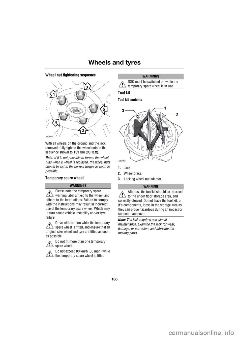
Wheel nut tightening sequence
With all wheels on the ground and the jack
removed, fully tighten the wheel nuts in the
sequence shown to 133 Nm (98 lb.ft).
Note: If it is not possible to torque the wheel
nuts when a wheel is replaced, the wheel nuts
should be set to the correct torque as soon as
possible.
Temporary spare wheel Tool kit
Tool kit contents
1.
Jack.
2. Wheel brace.
3. Locking wheel nut adapter.
Note: The jack requi res occasional
maintenance. Examine the jack for wear,
damage, or corrosion, and lubricate the
moving parts.
WARNINGS
Please note the temporary spare
warning label affixed to the wheel, and
adhere to the instructions. Failure to comply
with the instructions may result in incorrect
use of the temporary spare wheel. Which may
in turn cause vehicle instability and/or tyre
failure.
Drive with caution while the temporary
spare wheel is fitted, and ensure that an
original size wheel and tyre are fitted as soon
as possible.
Do not fit more than one temporary
spare wheel.
Do not exceed 80 km/h (50 mph) while
the temporary spare wheel is fitted.
E83968
5
1
3
2
4
DSC must be switched on while the
temporary spare wheel is in use.
WARNING
After use the tool kit should be returned
to the under floor storage area, and
correctly stowed. Do not leave the tool kit, or
it's components, loose in the storage area as
they can prove hazardous during an impact or
sudden manoeuvre.
WARNINGS
3
E80162
1
2
Page 2907 of 3229

187
Wheels and tyres
R
Locking wheel nuts
Locking wheel nuts can only be removed using
the special adapter provided in the tool kit.
Note: When the vehicle is first supplied the
adapter may be stored in the glove
compartment. It should be removed and stored
in the tool kit as soon as possible.
Note: A code number is stamped onto the
underside of the adapter. This number must be
recorded on the security card supplied with the
literature pack. If a replacement adapter is
required you will be asked to quote this
number. The security card must be kept safe,
but should not be kept with the vehicle.
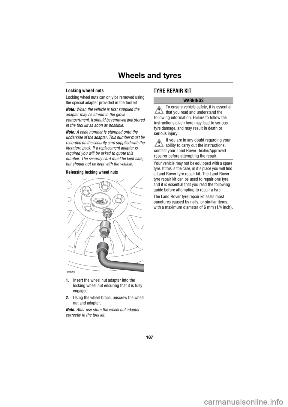
Releasing locking wheel nuts
1. Insert the wheel nut adapter into the
locking wheel nut ensuri ng that it is fully
engaged.
2. Using the wheel brace, unscrew the wheel
nut and adapter.
Note: After use store the wheel nut adapter
correctly in the tool kit.
TYRE REPAIR KIT
Your vehicle may not be equipped with a spare
tyre. If this is the case, in it's place you will find
a Land Rover tyre repair kit. The Land Rover
tyre repair kit can be us ed to repair one tyre,
and it is essential that you read the following
guide before attempting to repair a tyre.
The Land Rover tyre repair kit seals most
punctures caused by nails , or similar items,
with a maximum diameter of 6 mm (1/4 inch).
E83969
WARNINGS
To ensure vehicle safety, it is essential
that you read and understand the
following information. Failure to follow the
instructions given here may lead to serious
tyre damage, and may result in death or
serious injury.
If you are in any doubt regarding your
ability to carry out the instructions,
contact your Land Ro ver Dealer/Approved
repairer before attempting the repair.
Page 2912 of 3229

Wheels and tyres
192
L
9. To check the tyre pressure turn off the
compressor then read the pressure from
the gauge.
10. When the compressor is off, if the tyre
pressure is too high, release the required
amount of pressure using the pressure
relief valve.
11. Once the tyre is inflated to the correct
pressure, switch off the compressor and
remove the power plug from the auxiliary
socket.
12. Unscrew the inflation hose connector from
the tyre valve, replace the tyre valve cap
and the inflation hose connector protective
cap.
13. Do not remove the sealant bottle from the
receiver.
14. Ensure that the tyre repair kit (including
the bottle, and receiver caps) are placed
securely in the vehicle.
15. Drive to the nearest tyre repair centre, or
Land Rover Dealer/Autho rised repairer for
a replacement tyre to be fitted. Ensure that
you make the repair centre aware that the
tyre repair kit has been used before the tyre
is removed.
16. Both the tyre inflation hose, and the sealant
bottle should be replac ed once a new tyre
has been fitted.
Only sealant bottles which are
completely empty should be
disposed of with normal household
waste. Sealant bottles which contain some
sealant, and the tyre in flation hose, should be
disposed of by a tyre specialist, or your Land
Rover Dealer/Authorised repairer in
compliance with local waste disposal
regulations.USING SNOW CHAINS
Land Rover approved trac tion devices may be
used to improve traction on a hard road surface
in heavy snow conditions . They should not be
used in off-road conditions.
If it becomes necessary to fit traction devices,
the following points should be observed:-
• Single sided Spike-spyder traction devices
can only be fitted to the front wheels of
vehicles fitted with 17 or 18 inch diameter
wheels.
• The wheels and tyres fitted must
conform to the specifications of the
original equipment.
• No traction devices should be fitted to the
rear wheels.
• Only Land Rover approved traction devices
should be used on the vehicle. Only Land
Rover approved tracti on devices have been
tested to ensure that they do not cause
damage to the vehicl e. Contact your Land
Rover Dealer/Authorised repairer for
information.
• Always read, understa nd, and follow the
snow chain manufacturer's instructions.
Pay particular attention to the maximum
speed, and fitti ng instructions.
WARNING
Only use traction devices in heavy snow
conditions, on hard road surfaces.
Dynamic Stability Control (DSC) must be
switched off when using traction devices. DSC
limits wheel spin which is required to maintain
traction in deep snow conditions.
Never exceed 50 km/h (30 mph) when traction
devices are fitted.
Never fit traction devices to a temporary use
spare wheel.
Page 2932 of 3229

Technical specifications
212
L
WEIGHTS
¹ This figure includes the tool kit, all fluids to
the correct levels, and spare wheel, but
excludes the driver and passengers.
² The maximum permissi ble weight of the
vehicle including passengers and load. ³ The maximum permissi
ble weight of the
vehicle and braked trailer including their
respective loads.
Note: ¹ The front and rear axle maximum loads
can not be reached simult aneously as this will
exceed the GVW limit.
² This figure includes the weight of the roof
rack. Variant Approximate unladen
weight¹ Gross Vehicle Weight
(GVW)² Gross Train Weight³
Petrol 1825 kg 4020 lbs 2505 kg
5520 lbs 4505 kg
9930 lbs
Diesel 1820 kg 4010 lbs 2505 kg
5520 lbs 4505 kg
9935 lbs
Variant Maximum front axle load¹ Maximum rear
axle load¹ Maximum roof
rack load² Maximum
payload
Petrol and Diesel 1310 kg 2885 lbs 1360 kg
2995 lbs 75 kg
165 lbs 500 kg
1100 lbs
Page 2992 of 3229

Index
272
L
Changing a bulb . . . . . . . . . . . . . . . . . . . . 77 Front fog lamp . . . . . . . . . . . . . . . . . . . 81
General information . . . . . . . . . . . . . . . 77
Headlamp unit bulbs . . . . . . . . . . . . . . . 79
High level brake lamp . . . . . . . . . . . . . . 83
Interior lamp bulbs . . . . . . . . . . . . . . . . 85
Number plate lamp bulb . . . . . . . . . . . . 84
Rear lamp bulbs . . . . . . . . . . . . . . . . . . 82
Removing the headlamp unit . . . . . . . . 78
Removing the rear lamp unit . . . . . . . . . 82
Side repeater lamp . . . . . . . . . . . . . . . . 84
Changing a fuse. . . . . . . . . . . . . . . . . . . . 195
Changing a road wheel . . . . . . . . . . . . . . 183 Locking wheel nuts . . . . . . . . . . . . . . . 187
Positioning the jack. . . . . . . . . . . . . . . 185
Temporary spare wheel . . . . . . . . . . . . 186
Tool kit . . . . . . . . . . . . . . . . . . . . . . . . 186
Wheel changing safety . . . . . . . . . . . . 184
Wheel nut tightening sequence . . . . . . 186
Changing the vehicle battery . . . . . . . . . . 174
Battery disposal . . . . . . . . . . . . . . . . . 175
Disconnecting . . . . . . . . . . . . . . . . . . . 174
Effects of disconnecting . . . . . . . . . . . 175
Refitting . . . . . . . . . . . . . . . . . . . . . . . 175
Replacement batteries. . . . . . . . . . . . . 175
Changing the wiper blades . . . . . . . . . . . . 90 Changing the front wiper blades . . . . . . 91
Changing the rear wiper blades. . . . . . . 92
Service position . . . . . . . . . . . . . . . . . . 90
Channel automatic tuning . . . . . . . . . . . . 236
Channel options. . . . . . . . . . . . . . . . . . . . 236 Scanning channels . . . . . . . . . . . . . . . 238
Selecting a channel . . . . . . . . . . . . . . . 237
Selecting a subchannel . . . . . . . . . . . . 237
Selecting an ensemble . . . . . . . . . . . . 237
Signal availability . . . . . . . . . . . . . . . . 238
Charging the vehicle battery . . . . . . . . . . 174
Checking the wiper blades . . . . . . . . . . . . . 90
Child safety locks . . . . . . . . . . . . . . . . . . . 69
Child seats . . . . . . . . . . . . . . . . . . . . . . . . . 64 Child restraint check list . . . . . . . . . . . . 65
Cigar lighter . . . . . . . . . . . . . . . . . . . . . . . 109
Cleaning the alloy wheels . . . . . . . . . . . . 154 Cleaning the exterior . . . . . . . . . . . . . . . . . 154
Cleaning after off-road driving . . . . . . . 155
Washing the vehicle . . . . . . . . . . . . . . . 154
Cleaning the interior . . . . . . . . . . . . . . . . . 155
Airbag module covers . . . . . . . . . . . . . 156
Carpets and fabrics . . . . . . . . . . . . . . . 156
Instrument pack, clock, and audio equipment . . . . . . . . . . . . . . . . . . . . 156
Leather . . . . . . . . . . . . . . . . . . . . . . . . . 155
Plastic and cloth . . . . . . . . . . . . . . . . . . 155
Seat belts . . . . . . . . . . . . . . . . . . . . . . . 156
Clock. . . . . . . . . . . . . . . . . . . . . . . . . . . . . 107
Setting the clock - Premium audio . . . . 107
Setting the clock - Standard audio . . . . 108
Compact disc display options . . . . . . . . . . 247
Compact disc function menu . . . . . . . . . . 247
Compact disc pause . . . . . . . . . . . . . . . . . 246
Compact disc playback . . . . . . . . . . . . . . . 246
Compact disc selection . . . . . . . . . . . . . . . 246
Compact disc track scanning . . . . . . . . . . 248 CD scan - Premium audio . . . . . . . . . . 248
CD Scan - Standard audio . . . . . . . . . . 249
Coolant check . . . . . . . . . . . . . . . . . . . . . . 163
Cruise control . . . . . . . . . . . . . . . . . . . . . . 130
Principle of operation . . . . . . . . . . . . . . 130
Cup holders . . . . . . . . . . . . . . . . . . . . . . . 111
D
Diesel particulate filter (DPF) . . . . . . . . . . 116 Regeneration . . . . . . . . . . . . . . . . . . . . 116
Warning indicators and messages . . . . 117
Digital audio broadcasting General information . . . . . . . . . . . . . . . 234
Dimensions. . . . . . . . . . . . . . . . . . . . . . . . 213
Clutch and brake pedal travel (China only) .
214
Wheel alignment data (China only). . . . 214
Direction indicators. . . . . . . . . . . . . . . . . . . 75
Disabling the passenger airbag . . . . . . . . . . 62 Operational status indicator . . . . . . . . . . 63
Disarming the alarm . . . . . . . . . . . . . . . . . . 46 Deactivating the alarm when triggered . . 46
Disarming when the unlock button fails to
work. . . . . . . . . . . . . . . . . . . . . . . . . . 46
Display options . . . . . . . . . . . . . . . . . . . . . 236
DPF . . . . . . . . . . . . . . . . . . . . . . . . . . . . . . 116