2006 LAND ROVER FRELANDER 2 ignition
[x] Cancel search: ignitionPage 1770 of 3229
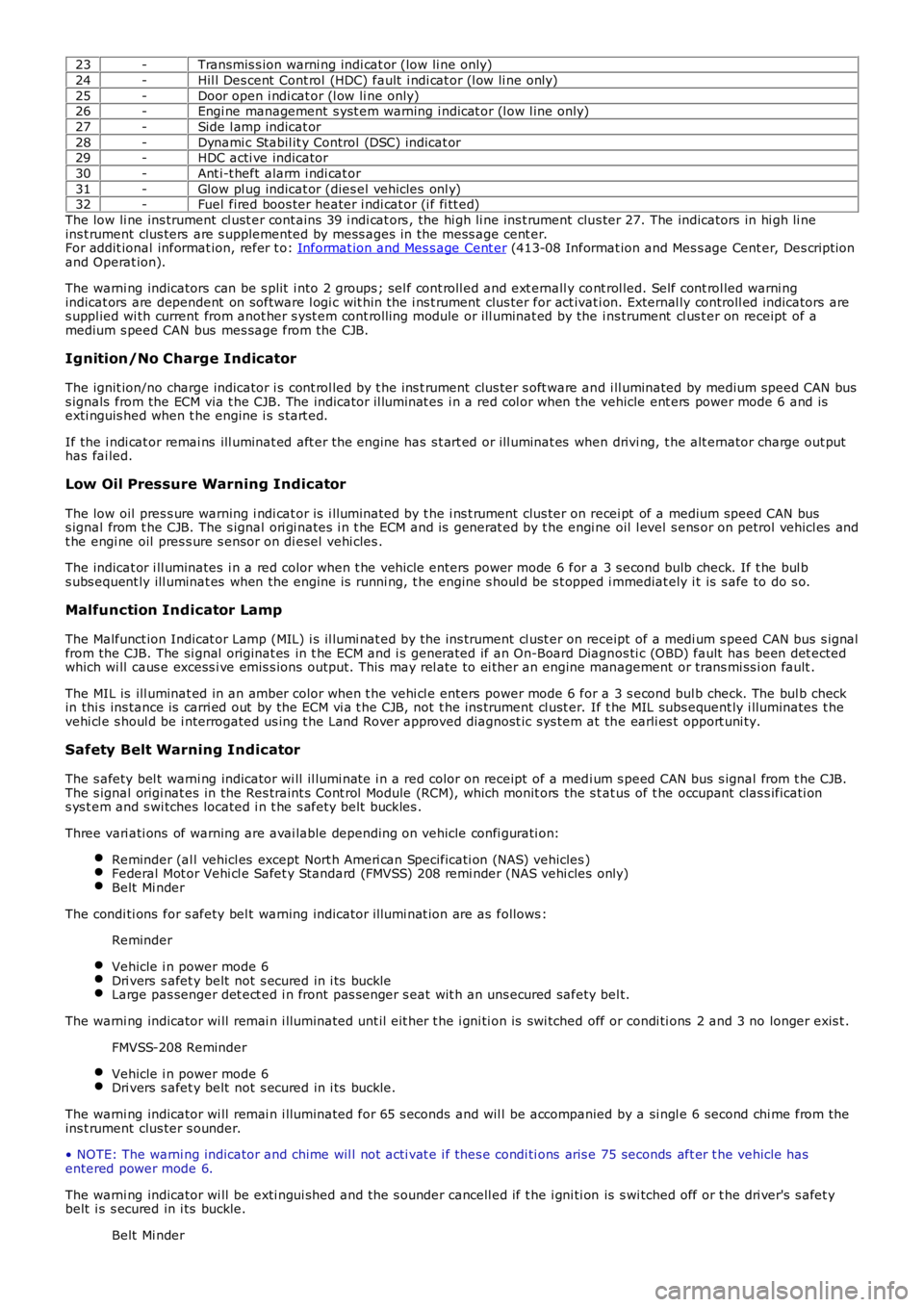
23-Transmis s ion warni ng indi cat or (low li ne only)
24-Hil l Des cent Cont rol (HDC) fault i ndi cat or (l ow li ne only)
25-Door open i ndi cat or (l ow li ne only)26-Engi ne management s yst em warning i ndicat or (l ow l ine only)
27-Side l amp indicat or
28-Dynami c Stabil it y Control (DSC) indicat or29-HDC acti ve indicator
30-Ant i-t heft alarm i ndi cat or
31-Glow pl ug indicat or (dies el vehicles onl y)32-Fuel fired boos ter heater i ndi cat or (i f fi tt ed)
The low li ne ins trument cl ust er cont ains 39 i ndi cat ors , the hi gh li ne ins t rument clus ter 27. The indicators in hi gh li neins t rument clus ters are s upplemented by mess ages in the mess age cent er.For addit ional informat ion, refer t o: Informat ion and Mes s age Cent er (413-08 Informat ion and Mes s age Cent er, Des cript ionand Operat ion).
The warni ng indicators can be s plit i nto 2 groups ; sel f cont roll ed and ext ernall y cont rol led. Self cont rol led warni ngindicat ors are dependent on software l ogi c wit hin t he i ns t rument clus ter for act ivati on. External ly controll ed indicators ares uppl ied wi th current from anot her s yst em cont roll ing module or ill uminat ed by the ins trument cl us t er on receipt of amedium s peed CAN bus mes sage from the CJB.
Ignition/No Charge Indicator
The ignit ion/no charge indicator i s cont rol led by t he ins t rument clus ter s oft ware and i ll uminated by medium speed CAN buss ignals from the ECM via t he CJB. The indicator il lumi nat es i n a red col or when the vehicle ent ers power mode 6 and isexti nguis hed when t he engine i s s tart ed.
If the i ndi cat or remai ns ill uminat ed aft er the engine has s t art ed or ill uminat es when drivi ng, t he alt ernator charge out puthas fai led.
Low Oil Pressure Warning Indicator
The low oil pres s ure warning i ndi cat or is i lluminated by t he i ns t rument clus ter on recei pt of a medium speed CAN buss ignal from t he CJB. The s ignal ori gi nates i n t he ECM and is generat ed by t he engi ne oil l evel s ens or on petrol vehicl es andt he engi ne oil pres s ure s ensor on di esel vehi cles .
The indicat or i ll uminates i n a red color when t he vehi cl e enters power mode 6 for a 3 s econd bulb check. If t he bul bs ubs equent ly ill uminat es when the engine is runni ng, t he engine s houl d be s t opped i mmediat ely i t is s afe to do s o.
Malfunction Indicator Lamp
The Malfunct ion Indicat or Lamp (MIL) i s il lumi nat ed by t he ins trument cl ust er on receipt of a medi um s peed CAN bus s ignalfrom the CJB. The si gnal originat es in t he ECM and i s generated if an On-Board Diagnos ti c (OBD) fault has been det ectedwhich wi ll caus e excess i ve emis s ions output. Thi s may rel ate to ei ther an engine management or trans mi ss i on fault .
The MIL is ill uminat ed in an amber color when t he vehi cl e enters power mode 6 for a 3 s econd bul b check. The bul b checkin thi s ins tance is carri ed out by the ECM vi a t he CJB, not t he ins trument cl ust er. If t he MIL subs equent ly i lluminates t hevehi cl e s houl d be i nterrogated us ing t he Land Rover approved diagnost ic sys tem at the earli es t opport uni ty.
Safety Belt Warning Indicator
The s afety bel t warni ng indicator wi ll il lumi nat e i n a red color on receipt of a medi um s peed CAN bus s ignal from t he CJB.The s ignal origi nat es in the Res traint s Cont rol Module (RCM), which monit ors the s t at us of t he occupant clas s ificati ons ys t em and s wi tches located i n t he s afety bel t buckles .
Three vari ati ons of warning are avai lable depending on vehicle confi gurati on:
Reminder (al l vehicl es except Nort h Ameri can Specificati on (NAS) vehicles )Federal Mot or Vehi cl e Safet y Standard (FMVSS) 208 remi nder (NAS vehi cles only)Belt Mi nder
The condi ti ons for s afety bel t warning indicator il lumi nat ion are as follows :
Reminder
Vehicle i n power mode 6Dri vers s afet y belt not s ecured in i ts buckleLarge pas senger det ect ed i n front pas s enger s eat wit h an uns ecured safety bel t.
The warni ng indicator wi ll remai n i lluminated unt il eit her t he i gni ti on is swi tched off or condi ti ons 2 and 3 no longer exis t .
FMVSS-208 Reminder
Vehicle i n power mode 6Dri vers s afet y belt not s ecured in i ts buckle.
The warni ng indicator wi ll remai n i lluminated for 65 s econds and wil l be accompanied by a si ngl e 6 second chi me from theins t rument clus ter s ounder.
• NOTE: The warni ng indicator and chime wil l not acti vat e i f thes e condi ti ons aris e 75 seconds aft er t he vehicle hasentered power mode 6.
The warni ng indicator wi ll be exti ngui shed and t he s ounder cancell ed if t he i gni ti on is s wi tched off or t he dri ver's s afet ybelt i s s ecured in i ts buckle.
Belt Mi nder
Page 1791 of 3229
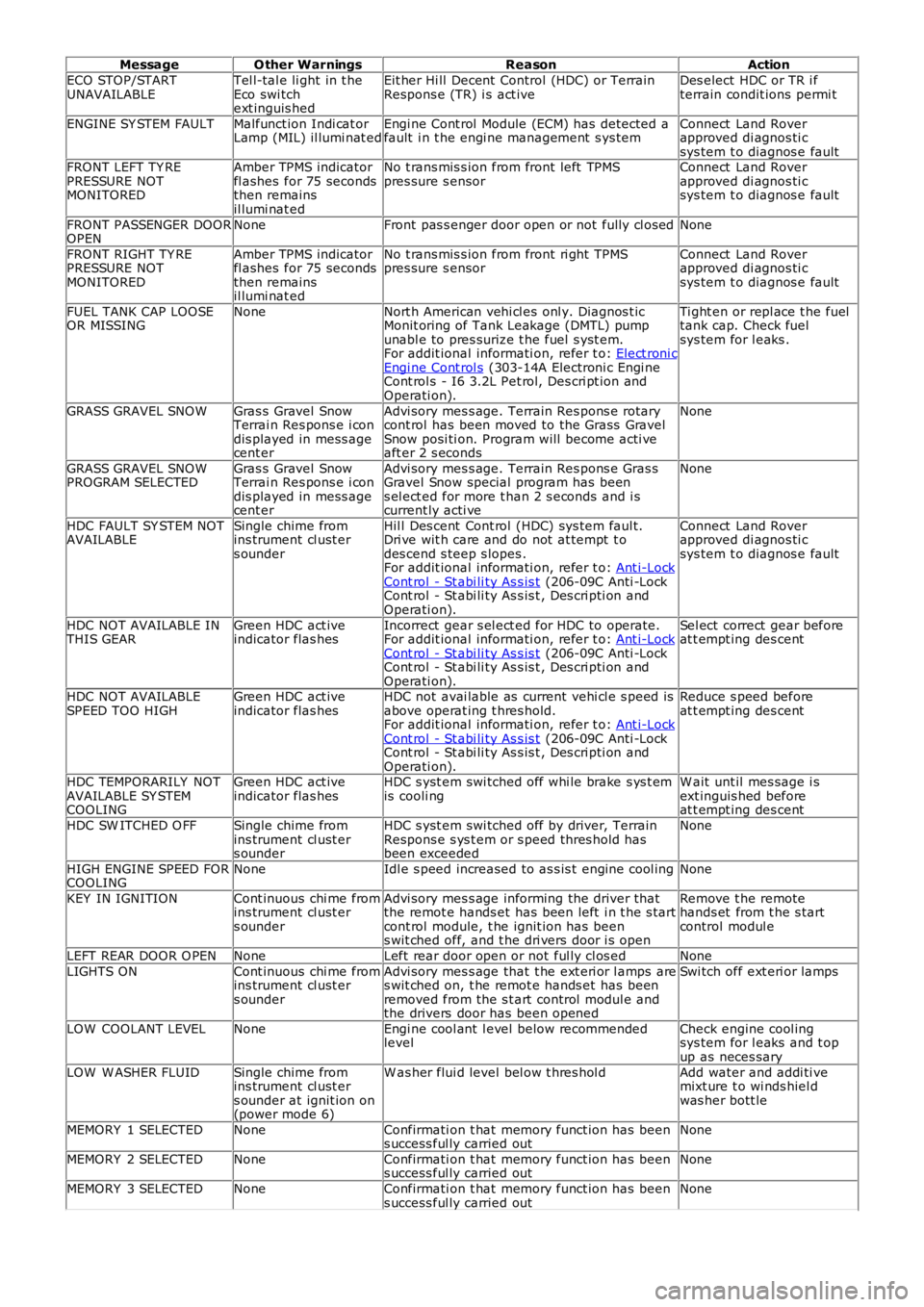
MessageO ther WarningsReasonAction
ECO STOP/STARTUNAVAILABLETel l-tal e li ght in t heEco swi tchext inguis hed
Eit her Hi ll Decent Control (HDC) or TerrainRespons e (TR) i s act iveDes elect HDC or TR i fterrain condit ions permi t
ENGINE SY STEM FAULTMalfunct ion Indi cat orLamp (MIL) il lumi nat edEngi ne Cont rol Module (ECM) has detected afault i n t he engi ne management s ys temConnect Land Roverapproved di agnos ti csys tem t o diagnos e faultFRONT LEFT TY REPRESSURE NOTMONITORED
Amber TPMS indicatorfl ashes for 75 secondsthen remainsil lumi nat ed
No t rans mis s ion from front left TPMSpres sure s ensorConnect Land Roverapproved di agnos ti csys tem t o diagnos e fault
FRONT PASSENGER DOOROPENNoneFront pas s enger door open or not fully cl osedNone
FRONT RIGHT TY REPRESSURE NOTMONITORED
Amber TPMS indicatorfl ashes for 75 secondsthen remainsil lumi nat ed
No t rans mis s ion from front ri ght TPMSpres sure s ensorConnect Land Roverapproved di agnos ti csys tem t o diagnos e fault
FUEL TANK CAP LOOSEOR MISSINGNoneNort h American vehi cl es onl y. Diagnos t icMonit oring of Tank Leakage (DMTL) pumpunabl e to pres surize t he fuel s yst em.For addit ional informati on, refer t o: Elect roni cEngi ne Cont rol s (303-14A Electroni c Engi neCont rol s - I6 3.2L Pet rol, Des cri pt ion andOperati on).
Ti ght en or repl ace t he fueltank cap. Check fuelsys tem for l eaks .
GRASS GRAVEL SNOWGras s Gravel SnowTerrai n Res pons e i condis played in mess agecent er
Advi sory mes s age. Terrain Res pons e rotarycont rol has been moved to the Grass GravelSnow posi ti on. Program will become acti veaft er 2 s econds
None
GRASS GRAVEL SNOWPROGRAM SELECTEDGras s Gravel SnowTerrai n Res pons e i condis played in mess agecent er
Advi sory mes s age. Terrain Res pons e Gras sGravel Snow special program has beens el ect ed for more t han 2 s econds and i scurrent ly acti ve
None
HDC FAULT SY STEM NOTAVAILABLESingle chime fromins trument cl ust ers ounder
Hil l Des cent Cont rol (HDC) sys tem faul t.Dri ve wit h care and do not at tempt t odes cend s teep s lopes .For addit ional informati on, refer t o: Ant i-LockCont rol - St abi li ty As s is t (206-09C Anti -LockCont rol - St abi li ty As s is t , Des cri pti on andOperati on).
Connect Land Roverapproved di agnos ti csys tem t o diagnos e fault
HDC NOT AVAILABLE INTHIS GEARGreen HDC act iveindicator flas hesIncorrect gear s el ect ed for HDC to operate.For addit ional informati on, refer t o: Ant i-LockCont rol - St abi li ty As s is t (206-09C Anti -LockCont rol - St abi li ty As s is t , Des cri pti on andOperati on).
Sel ect correct gear beforeat t empt ing des cent
HDC NOT AVAILABLESPEED TOO HIGHGreen HDC act iveindicator flas hesHDC not avai lable as current vehi cl e s peed isabove operat ing t hres hold.For addit ional informati on, refer t o: Ant i-LockCont rol - St abi li ty As s is t (206-09C Anti -LockCont rol - St abi li ty As s is t , Des cri pti on andOperati on).
Reduce s peed beforeat t empt ing des cent
HDC TEMPORARILY NOTAVAILABLE SY STEMCOOLING
Green HDC act iveindicator flas hesHDC s yst em swi tched off whi le brake s ys t emis cooli ngW ait unt il mes sage i sext inguis hed beforeat t empt ing des cent
HDC SW ITCHED O FFSingle chime fromins trument cl ust ers ounder
HDC s yst em swi tched off by driver, TerrainRespons e s ys t em or s peed thres hold hasbeen exceeded
None
HIGH ENGINE SPEED FORCOOLINGNoneIdl e s peed increased to as s is t engine cool ingNone
KEY IN IGNITIONCont inuous chi me fromins trument cl ust ers ounder
Advi sory mes s age informing the driver thatthe remot e hands et has been left i n t he s tartcont rol module, t he ignit ion has beens wit ched off, and t he dri vers door i s open
Remove t he remotehands et from t he s tartcontrol modul e
LEFT REAR DOOR O PENNoneLeft rear door open or not ful ly cl os edNone
LIGHTS ONCont inuous chi me fromins trument cl ust ers ounder
Advi sory mes s age that t he ext eri or l amps ares wit ched on, t he remot e hands et has beenremoved from the s t art control modul e andthe drivers door has been opened
Swi tch off ext eri or lamps
LOW COOLANT LEVELNoneEngi ne cool ant l evel below recommendedlevelCheck engine cool ingsys tem for l eaks and t opup as neces sary
LOW W ASHER FLUIDSingle chime fromins trument cl ust ers ounder at ignit ion on(power mode 6)
W as her flui d level bel ow t hres hol dAdd water and addi ti vemixt ure t o wi nds hiel dwas her bott le
MEMORY 1 SELECTEDNoneConfirmati on t hat memory funct ion has beens uccess ful ly carried outNone
MEMORY 2 SELECTEDNoneConfirmati on t hat memory funct ion has beens uccess ful ly carried outNone
MEMORY 3 SELECTEDNoneConfirmati on t hat memory funct ion has beens uccess ful ly carried outNone
Page 1825 of 3229
1
2
1
2
3
4
5
6
1
1
SymptomPossible CauseAction
faul tBat tery cable - faultCAN Bus - ci rcuit faul tEngine control modul ei nt ernal faul tCentral junct ion box
Check t hat the pul ley does not rotat eindependentl y of the generat orCheck for DTCs indicati ng a CAN, cent ral junct ionbox or engi ne cont rol module fault
Charge warning l amp int ermi tt entAcces s ory drive belts li ppi ngBat tery cable - faultGenerat or - ci rcuit faul tGenerat or - internalfaul tCAN Bus - ci rcuit faul t
• NOTE: Us e of a power pack or boost charger may bringthe warning l amp on unt il dis connected
Check t he acces s ory drive belt condi ti on andtens ionCheck t he batt ery and generat or cables refer t othe el ect ri cal guidesCheck for DTCs indicati ng a generator or CANcircuit fault
Batt ery di s charges wi thout t hecharge warni ng lamp s taying onBat tery - faultBat tery qui escent drainIntermit tent generator- faul t
Check t he batt ery condit ionCheck for bat t ery quies cent drai nCheck for DTCs indicati ng a generator faul tIf no ot her reas on for dis charge can be found,check t he circuit . Refer t o t he elect rical guides
Nois e (mechani cal )Acces s ory drive belts li ppi ngCheck t he acces s ory drive belt condi ti on andtens ionDis connect the access ory drive bel t and checkthat t he generator rot ates freel y
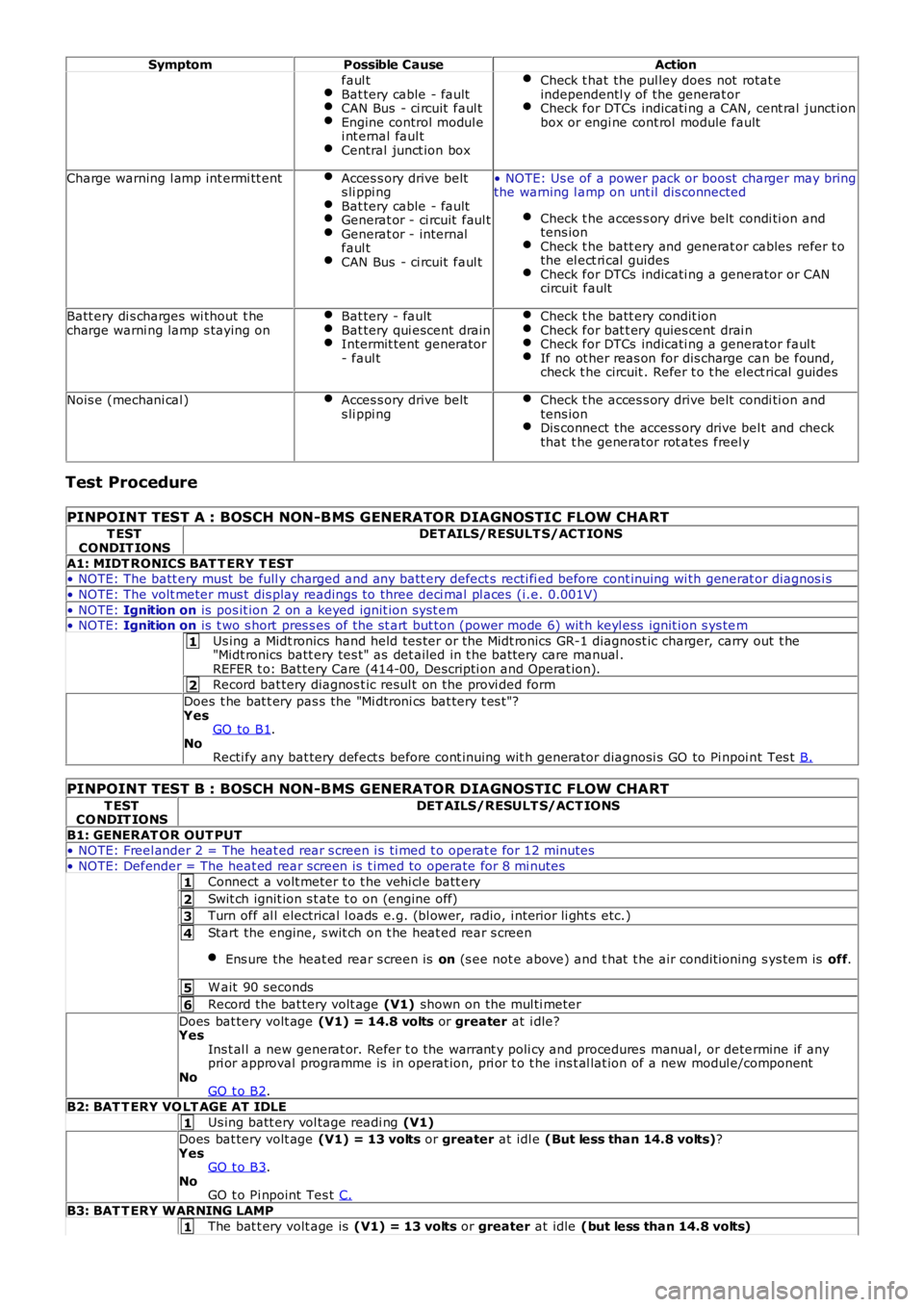
Test Procedure
PINPOINT TEST A : BOSCH NON-BMS GENERATOR DIAGNOSTIC FLOW CHART
T ESTCONDIT IONSDET AILS/RESULT S/ACT IONS
A1: MIDT RONICS BAT T ERY T EST• NOTE: The batt ery must be full y charged and any batt ery defect s recti fi ed before cont inuing wi th generat or diagnos i s
• NOTE: The volt meter mus t dis play readings to three deci mal pl aces (i.e. 0.001V)
• NOTE: Ignition on is pos it ion 2 on a keyed ignit ion s yst em• NOTE: Ignition on is t wo s hort pres s es of the st art but ton (power mode 6) wit h keyl ess ignit ion s ys tem
Us ing a Midt ronics hand held tes ter or t he Midt ronics GR-1 diagnost ic charger, carry out t he"Midt ronics batt ery tes t" as det ailed in t he batt ery care manual .REFER t o: Bat tery Care (414-00, Descripti on and Operat ion).
Record bat tery diagnos t ic resul t on the provi ded form
Does t he bat t ery pas s the "Mi dtroni cs bat tery t es t "?YesGO to B1.NoRecti fy any bat tery defect s before cont inuing wit h generator diagnosi s GO to Pi npoi nt Tes t B.
PINPOINT TEST B : BOSCH NON-BMS GENERATOR DIAGNOSTIC FLOW CHART
T ESTCO NDIT IONSDET AILS/RESULT S/ACT IONS
B1: GENERAT OR OUT PUT• NOTE: Freel ander 2 = The heat ed rear s creen i s ti med t o operat e for 12 minutes
• NOTE: Defender = The heat ed rear s creen is t imed to operate for 8 mi nutes
Connect a volt meter t o t he vehi cl e batt ery
Swit ch ignit ion s t ate t o on (engine off)
Turn off al l electrical l oads e.g. (bl ower, radio, i nteri or li ght s etc.)
Start the engine, s wit ch on t he heat ed rear s creen
Ens ure the heat ed rear s creen is on (s ee not e above) and t hat t he air condit ioning s ys tem is off.
W ait 90 seconds
Record the bat tery volt age (V1) shown on the mul ti meter
Does bat tery volt age (V1) = 14.8 volts or greater at i dle?YesIns t al l a new generat or. Refer t o the warrant y poli cy and procedures manual, or determine if anypri or approval programme is in operat ion, pri or t o t he ins t al lat ion of a new modul e/componentNoGO t o B2.
B2: BAT T ERY VO LT AGE AT IDLE
Us ing batt ery vol tage readi ng (V1)
Does bat tery volt age (V1) = 13 volts or greater at idl e (But less than 14.8 volts)?YesGO t o B3.NoGO t o Pi npoint Tes t C.
B3: BAT T ERY WARNING LAMP
The bat t ery volt age is (V1) = 13 volts or greater at idle (but less than 14.8 volts)
Page 2062 of 3229
Publi s hed: 11-May-2011
Anti-Theft - Passive - Anti-Theft - Passive
Diagnosi s and Tes ti ng
Principles of Operation
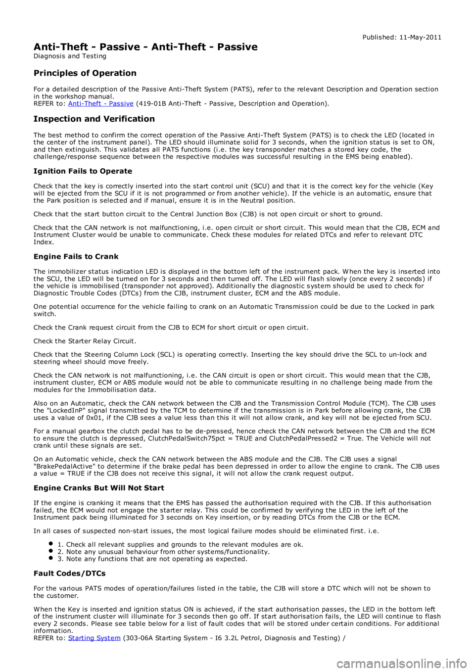
For a detail ed descripti on of the Pas s ive Ant i-Theft Sys t em (PATS), refer t o t he relevant Des cript ion and Operat ion secti onin the workshop manual.REFER to: Ant i-Theft - Pas s ive (419-01B Anti -Theft - Pas s ive, Descripti on and Operat ion).
Inspection and Verification
The best method t o confirm the correct operat ion of t he Pass i ve Ant i-Theft Syst em (PATS) is t o check t he LED (located i nt he cent er of t he ins t rument panel ). The LED s hould i ll uminate sol id for 3 s econds , when the i gnit ion s tat us is set t o ON,and t hen ext inguis h. Thi s validat es all PATS functi ons (i .e. the key t rans ponder matches a st ored key code, thechal lenge/res ponse sequence bet ween t he res pect ive modules was succes s ful res ult ing in t he EMS being enabled).
Ignition Fails to Operate
Check t hat the key i s correct ly i nserted i nto the s t art cont rol unit (SCU) and that i t is t he correct key for t he vehi cle (Keywil l be ejected from t he SCU i f it is not programmed or from anot her vehicl e). If the vehicle is an aut omati c, ens ure t hatt he Park pos it ion i s s el ect ed and if manual, ens ure it is in t he Neutral pos i ti on.
Check t hat the st art but ton circui t to the Cent ral Juncti on Box (CJB) i s not open circui t or s hort to ground.
Check t hat the CAN network is not mal functi oni ng, i .e. open circuit or s hort circui t. This woul d mean t hat the CJB, ECM andIns t rument Clus t er woul d be unabl e t o communicate. Check thes e modules for relat ed DTCs and refer t o relevant DTCIndex.
Engine Fails to Crank
The immobili zer s t atus i ndi cat ion LED i s dis played i n the bot tom left of the i nst rument pack. W hen the key i s i ns ert ed i nt ot he SCU, t he LED wi ll be t urned on for 3 s econds and t hen turned off. The LED will flas h s lowl y (once every 2 seconds ) i ft he vehi cl e is immobi lis ed (t ransponder not approved). Addit ionall y the di agnos ti c syst em s hould be us ed t o check forDiagnost ic Troubl e Codes (DTCs ) from the CJB, ins trument cl ust er, ECM and the ABS modul e.
One potent ial occurrence for the vehicl e fai ling to crank on an Automat ic Trans mi s sion coul d be due t o t he Locked in parks wit ch.
Check t he Crank reques t circui t from t he CJB t o ECM for short ci rcuit or open circuit .
Check t he St art er Rel ay Circuit .
Check t hat the St eeri ng Col umn Lock (SCL) is operat ing correctl y. Ins erti ng t he key should drive t he SCL t o un-l ock ands teeri ng wheel should move freel y.
Check t he CAN net work i s not malfunct ioning, i.e. the CAN ci rcuit i s open or short ci rcuit . Thi s would mean that t he CJB,ins t rument clus ter, ECM or ABS module would not be abl e t o communicate res ul ti ng in no chal lenge being made from t hemodules for the Immobil is ati on data.
Als o on an Aut omat ic, check the CAN network between t he CJB and the Transmis s ion Control Modul e (TCM). The CJB usest he "LockedInP" s ignal transmit ted by t he TCM to det ermi ne if t he t rans mis s ion i s in Park before all owing crank, the CJBus es a value of 0x01, i f the CJB s ees a value l ess than t his i t wil l not al low crank, and key wil l not be ejected from SCU.
For a manual gearbox t he clut ch pedal has to be de-pres s ed, hence check t he CAN network between t he CJB and t he ECMt o ensure t he cl utch i s depress ed, Clut chPedal Swit ch75pct = TRUE and Cl ut chPedalPress ed2 = True. The Vehicl e wil l notcrank unti l thes e s ignals are s et.
On an Aut omati c vehi cl e, check t he CAN network between t he ABS module and the CJB. The CJB uses a s ignal"BrakePedalActi ve" t o det ermi ne if t he brake pedal has been depres sed in order t o allow t he engine t o crank. The CJB us esa value = TRUE i f the CJB does not receive t hi s s ignal, i t wil l not al low t he crank reques t output.
Engine Cranks But Will Not Start
If the engine i s cranking i t means that t he EMS has pass ed t he authori s at ion required wit h t he CJB. If thi s authori s at ionfai led, the ECM would not engage the s t art er relay. Thi s coul d be confi rmed by verifyi ng t he LED in the l eft of t heIns t rument pack bei ng il lumi nat ed for 3 seconds on Key ins ert ion, or by reading DTCs from t he CJB or t he ECM.
In all cases of s us pected non-st art i s sues , the most l ogical fail ure modes s houl d be el imi nat ed first . i.e.
1. Check al l relevant suppli es and grounds to the relevant modul es are ok.2. Note any unus ual behavi our from other s yst ems /funct ionali ty.3. Note any funct ions t hat are not operati ng as expect ed.
Fault Codes/DTCs
For the vari ous PATS modes of operat ion/fail ures l is ted i n t he t abl e, t he CJB wi ll store a DTC whi ch wil l not be shown t ot he cus t omer.
W hen t he Key i s ins ert ed and ignit ion st atus ON is achieved, if t he s tart aut horis ation pas ses , the LED in t he bott om leftof the ins trument cl us t er will i ll uminate for 3 s econds t hen go off. If st art aut horis ati on fai ls , the LED wil l conti nue to fl as hevery 2 s econds . Pleas e s ee tabl e below for a li s t of fault codes that wil l be s tored under cert ain condi ti ons. For addi ti onalinformat ion.REFER to: St art ing Syst em (303-06A St art ing Sys tem - I6 3.2L Petrol, Di agnos is and Tes ti ng) /
Page 2063 of 3229
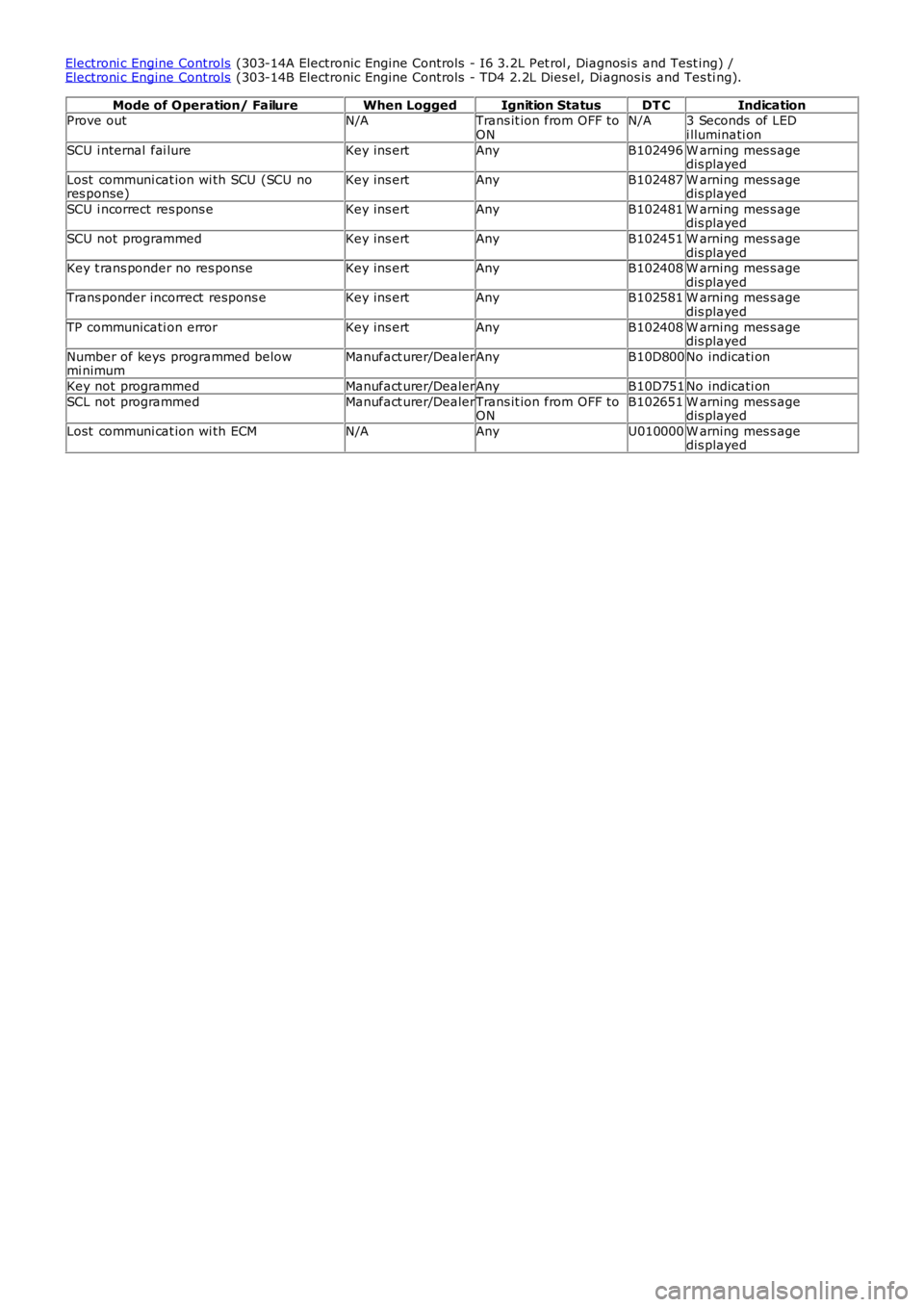
Electroni c Engine Controls (303-14A Electronic Engine Controls - I6 3.2L Pet rol , Diagnosi s and Test ing) /Electroni c Engine Controls (303-14B Electronic Engine Controls - TD4 2.2L Dies el, Di agnos is and Tes ti ng).
Mode of Operation/ FailureWhen LoggedIgnition StatusDT CIndicationProve outN/ATrans it ion from OFF toONN/A3 Seconds of LEDi lluminati on
SCU i nternal fai lureKey ins ertAnyB102496W arning mes s agedis played
Lost communi cat ion wi th SCU (SCU nores ponse)Key ins ertAnyB102487W arning mes s agedis played
SCU i ncorrect res pons eKey ins ertAnyB102481W arning mes s agedis played
SCU not programmedKey ins ertAnyB102451W arning mes s agedis playedKey t rans ponder no res ponseKey ins ertAnyB102408W arning mes s agedis playedTrans ponder incorrect respons eKey ins ertAnyB102581W arning mes s agedis played
TP communicati on errorKey ins ertAnyB102408W arning mes s agedis played
Number of keys programmed belowmi nimumManufact urer/DealerAnyB10D800No indicati on
Key not programmedManufact urer/DealerAnyB10D751No indicati on
SCL not programmedManufact urer/DealerTrans it ion from OFF toONB102651W arning mes s agedis played
Lost communi cat ion wi th ECMN/AAnyU010000W arning mes s agedis played
Page 2728 of 3229
8
Quick start
L
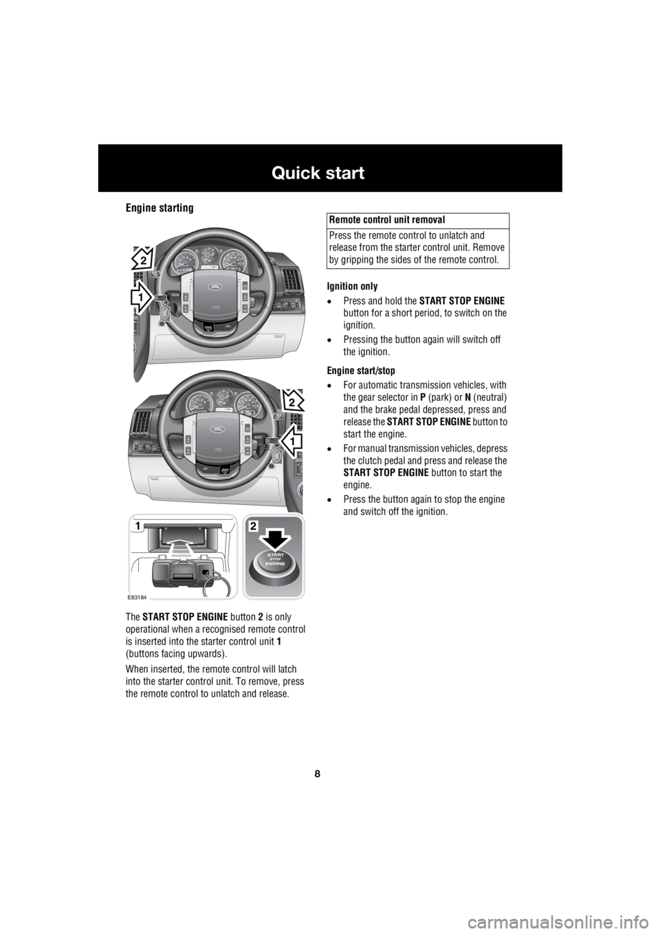
Engine starting
The START STOP ENGINE button 2 is only
operational when a rec ognised remote control
is inserted into the starter control unit 1
(buttons facing upwards).
When inserted, the remo te control will latch
into the starter control unit. To remove, press
the remote control to unlatch and release. Ignition only
• Press and hold the START STOP ENGINE
button for a short period, to switch on the
ignition.
• Pressing the button again will switch off
the ignition.
Engine start/stop
• For automatic transmission vehicles, with
the gear selector in P (park) or N (neutral)
and the brake pedal de pressed, press and
release the START STOP ENGINE button to
start the engine.
• For manual transmission vehicles, depress
the clutch pedal and press and release the
START STOP ENGINE button to start the
engine.
• Press the button again to stop the engine
and switch off the ignition.
1
EXT C23EXT F72EXT C21
EXT C23EXT F72EXT C21
1
1
2
2
E83184
2
Remote control unit removal
Press the remote control to unlatch and
release from the starter control unit. Remove
by gripping the sides of the remote control.
Page 2730 of 3229
10
Quick start
L
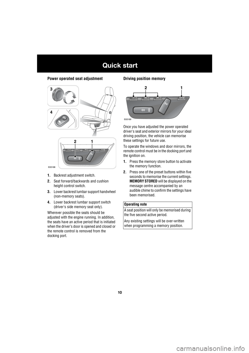
Power operated seat adjustment
1. Backrest adjustment switch.
2. Seat forward/backwards and cushion
height control switch.
3. Lower backrest lumbar support handwheel
(non-memory seats).
4. Lower backrest lumbar support switch
(driver's side memory seat only).
Wherever possible the seats should be
adjusted with the engine running. In addition,
the seats have an active period that is initiated
when the driver’s door is opened and closed or
the remote control is removed from the
docking port.
Driving position memory
Once you have adjusted the power operated
driver's seat and exterior mirrors for your ideal
driving position, the vehicle can memorise
these settings for future use.
To operate the windows and door mirrors, the
remote control must be in the docking port and
the ignition on.
1. Press the memory store button to activate
the memory function.
2. Press one of the preset buttons within five
seconds to memorise the current settings.
MEMORY STORED will be displayed on the
message centre accompanied by an
audible chime to confirm the settings have
been memorised.
E83188
12
3
4
Operating note
A seat position will onl y be memorised during
the five second active period.
Any existing settings w ill be over-written
when programming a memory position.
E83189
12
Page 2731 of 3229
11
Quick start
R
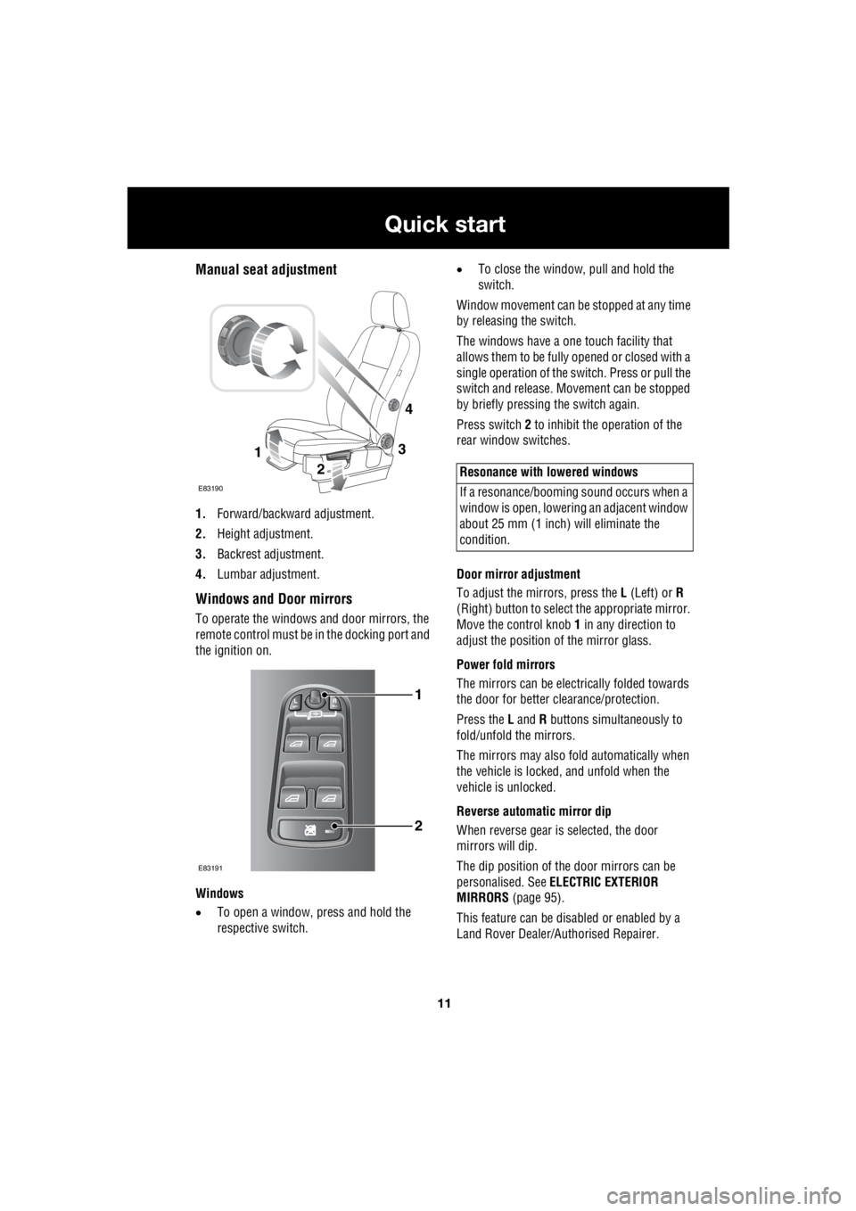
Manual seat adjustment
1. Forward/backward adjustment.
2. Height adjustment.
3. Backrest adjustment.
4. Lumbar adjustment.
Windows and Door mirrors
To operate the windows and door mirrors, the
remote control must be in the docking port and
the ignition on.
Windows
• To open a window, press and hold the
respective switch. •
To close the window, pull and hold the
switch.
Window movement can be stopped at any time
by releasing the switch.
The windows have a one touch facility that
allows them to be fully opened or closed with a
single operation of the switch. Press or pull the
switch and release. Mo vement can be stopped
by briefly pressing the switch again.
Press switch 2 to inhibit the operation of the
rear window switches.
Door mirror adjustment
To adjust the mirrors, press the L (Left) or R
(Right) button to select the appropriate mirror.
Move the control knob 1 in any direction to
adjust the position of the mirror glass.
Power fold mirrors
The mirrors can be electr ically folded towards
the door for better clearance/protection.
Press the L and R buttons simultaneously to
fold/unfold the mirrors.
The mirrors may also fold automatically when
the vehicle is locked, and unfold when the
vehicle is unlocked.
Reverse automatic mirror dip
When reverse gear is selected, the door
mirrors will dip.
The dip position of the door mirrors can be
personalised. See ELECTRIC EXTERIOR
MIRRORS (page 95).
This feature can be disabled or enabled by a
Land Rover Dealer/A uthorised Repairer.
3
2
1
E83190
4
1
2
E83191
Resonance with lowered windows
If a resonance/booming sound occurs when a
window is open, lowering an adjacent window
about 25 mm (1 inch) will eliminate the
condition.