2006 LAND ROVER FRELANDER 2 ignition
[x] Cancel search: ignitionPage 1111 of 3229
Publi s hed: 11-May-2011
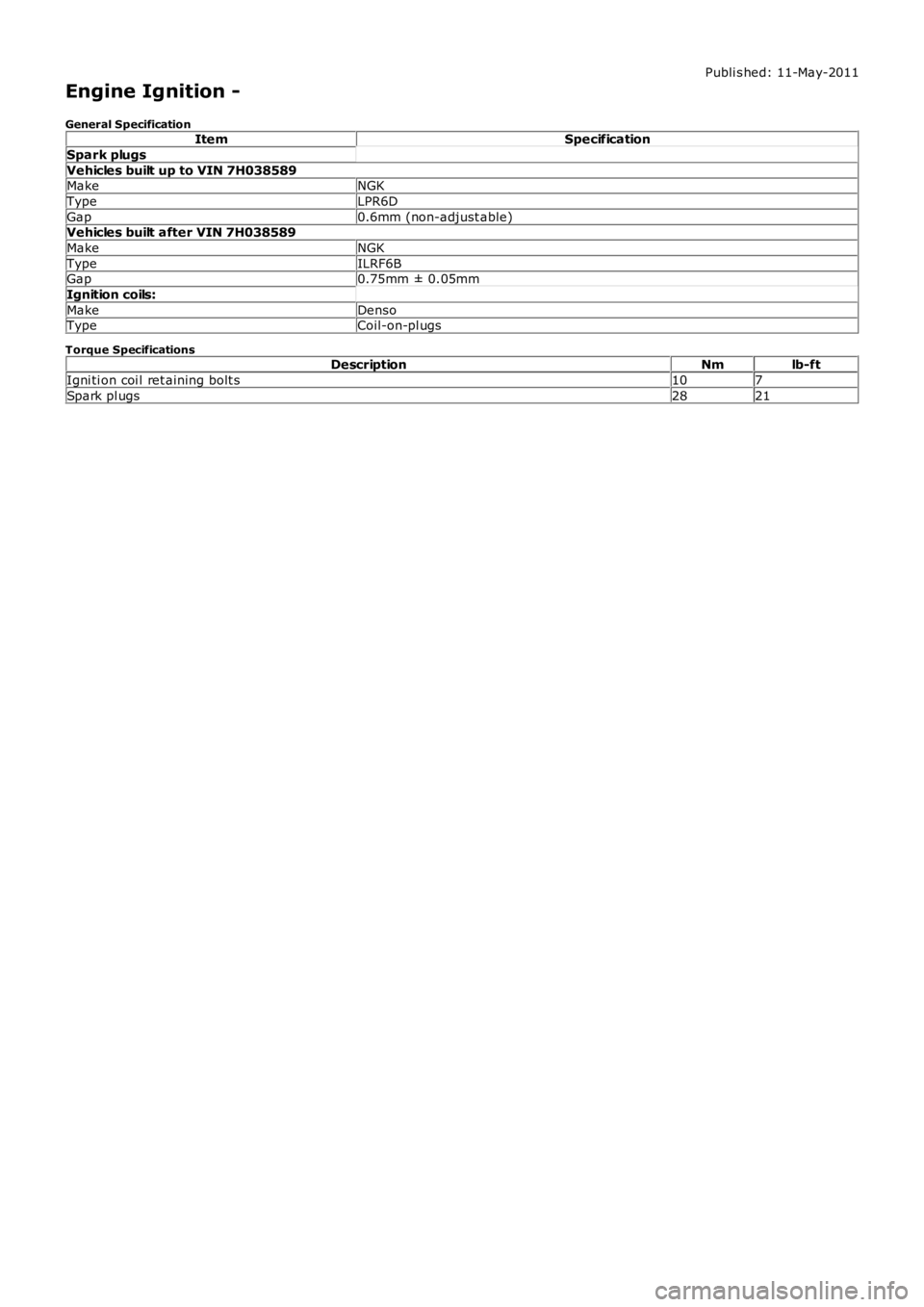
Engine Ignition -
General SpecificationItemSpecification
Spark plugs
Vehicles built up to VIN 7H038589MakeNGK
TypeLPR6D
Gap0.6mm (non-adjust able)Vehicles built after VIN 7H038589
MakeNGK
TypeILRF6BGap0.75mm ± 0.05mm
Ignition coils:
MakeDensoTypeCoil-on-pl ugs
Torque SpecificationsDescriptionNmlb-ft
Igni ti on coi l ret aining bolt s107
Spark pl ugs2821
Page 1112 of 3229
Publi s hed: 11-May-2011
Engine Ignition - Engine Ignition
Des cript ion and Operat ion
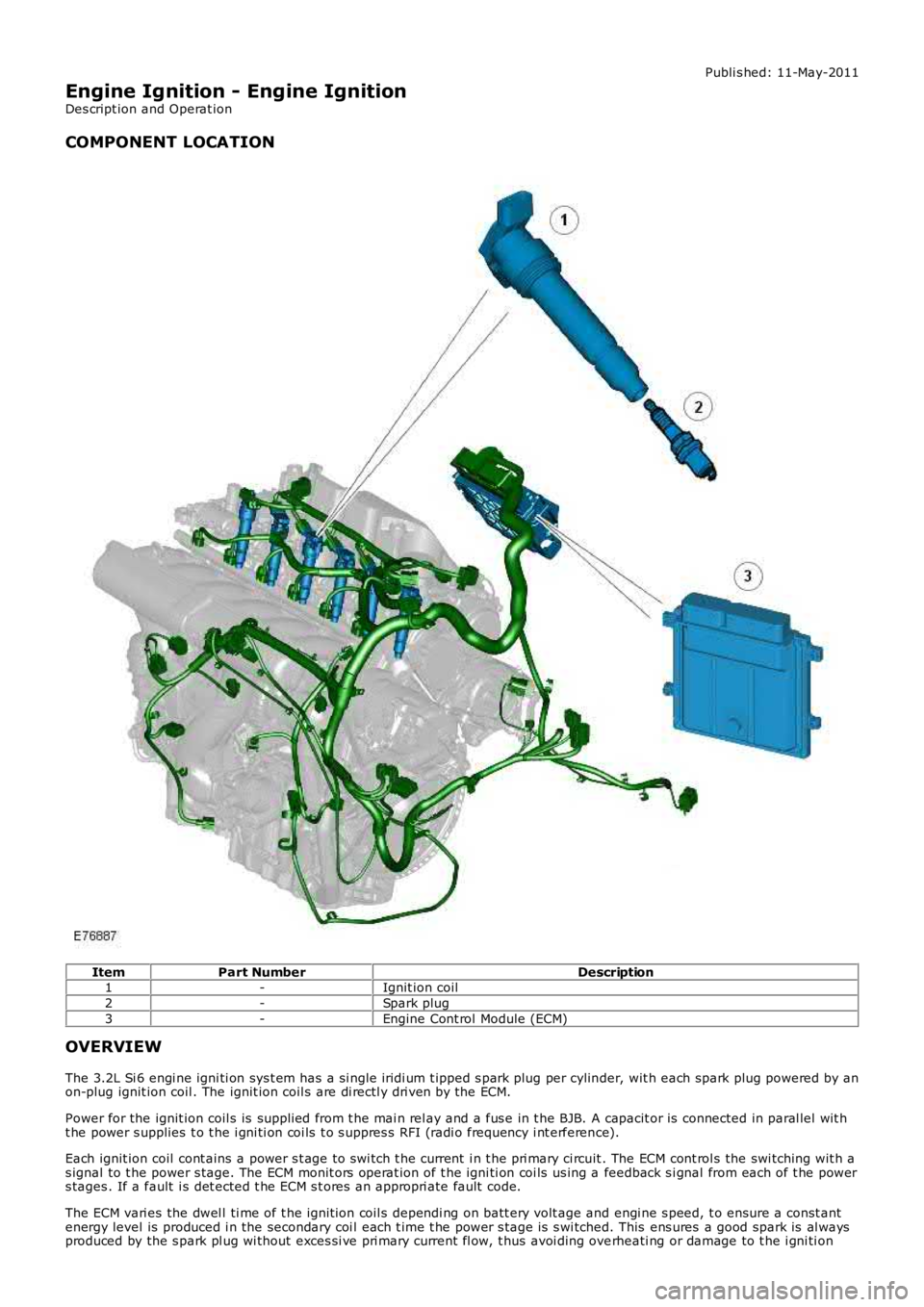
COMPONENT LOCATION
ItemPart NumberDescription1-Ignit ion coil
2-Spark plug
3-Engine Cont rol Module (ECM)
OVERVIEW
The 3.2L Si 6 engi ne igni ti on sys t em has a s i ngl e iridi um t ipped s park plug per cylinder, wit h each spark plug powered by anon-plug ignit ion coil . The ignit ion coil s are di rectl y dri ven by the ECM.
Power for the ignit ion coil s is suppli ed from t he mai n rel ay and a fus e in t he BJB. A capacit or is connected in paral lel wit ht he power s upplies t o t he i gni ti on coi ls t o s uppres s RFI (radi o frequency i nt erference).
Each ignit ion coil cont ains a power s t age to swi tch t he current i n t he pri mary ci rcuit . The ECM cont rol s the swi tching wit h as ignal to t he power s tage. The ECM monit ors operat ion of t he igni ti on coi ls us ing a feedback s i gnal from each of t he powers tages . If a fault i s det ected t he ECM s t ores an appropri ate fault code.
The ECM vari es the dwel l ti me of t he ignit ion coil s dependi ng on batt ery volt age and engi ne s peed, t o ensure a const antenergy level is produced i n the secondary coi l each t ime t he power s t age is s wi tched. This ens ures a good spark is al waysproduced by the s park pl ug wi thout exces si ve pri mary current fl ow, t hus avoi ding overheati ng or damage to t he i gni ti on
Page 1115 of 3229
Publi s hed: 11-May-2011
Engine Ignition - Engine Ignition
Diagnosi s and Tes ti ng
Principles of Operation
For a detail ed descripti on of the ignit ion s yst em, refer to the relevant Des cri pti on and Operati on s ect ion i n t he works hopmanual.REFER to: Engine Ignit ion (303-07A Engi ne Igni ti on, Des cript ion and O perati on).
Inspection and Verification
CAUTION: Di agnos is by s ubs ti tut ion from a donor vehicle is NO T acceptabl e. Subs ti tut ion of cont rol modules doesnot guarant ee confirmat ion of a faul t, and may als o caus e addit ional fault s i n t he vehi cl e being t est ed and/or t he donorvehi cl e.
1. Verify t he cus t omer concern.1.
2. Vis ually ins pect for obvious s igns of mechani cal or electrical damage.2.
Visual InspectionMechanicalElectrical
Engine oil l evelCooli ng sys t em cool ant levelFuel l evelFuel contami nati on/grade/quali ty
Fus esW iring harnes sLoos e or corroded electrical connect orsIgnit ion coil sSens or(s)Engine Cont rol Modul e (ECM)
3. If an obvious cause for an obs erved or report ed concern is found, correct t he caus e (if pos s ible) beforeproceeding t o t he next s t ep3.
4. If t he caus e is not vis ually evi dent , verify t he sympt om and refer t o t he Sympt om Chart, al ternat ively, check forDi agnos ti c Trouble Codes (DTCs) and refer t o t he DTC Index.4.
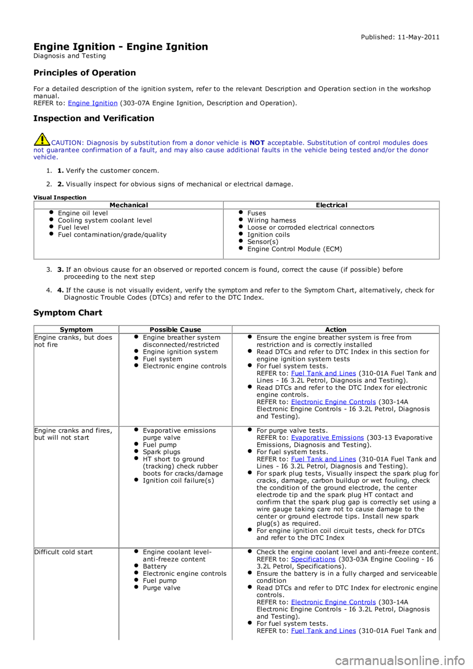
Symptom Chart
SymptomPossible CauseActionEngine cranks , but doesnot fi reEngine breat her sys temdis connected/res trict edEngine i gni ti on s ys t emFuel sys temElect ronic engine controls
Ens ure the engine breat her sys t em i s free fromres tricti on and is correctl y ins tal ledRead DTCs and refer t o DTC Index in t his s ecti on forengine ignit ion s ys tem tes tsFor fuel s yst em tes ts .REFER t o: Fuel Tank and Lines (310-01A Fuel Tank andLi nes - I6 3.2L Petrol, Diagnos is and Tes ti ng).Read DTCs and refer t o t he DTC Index for elect roni cengine cont rols .REFER t o: Electroni c Engi ne Control s (303-14AEl ect ronic Engi ne Cont rol s - I6 3.2L Pet rol, Di agnos isand Tes t ing).
Engine cranks and fires ,but wil l not s t artEvaporati ve emis s ionspurge val veFuel pumpSpark pl ugsHT short to ground(tracki ng) check rubberboots for cracks /damageIgni ti on coil fai lure(s )
For purge valve tes ts .REFER t o: Evaporat ive Emi s si ons (303-13 Evaporati veEmis s ions, Di agnos is and Tes t ing).For fuel s yst em tes ts .REFER t o: Fuel Tank and Lines (310-01A Fuel Tank andLi nes - I6 3.2L Petrol, Diagnos is and Tes ti ng).For s park pl ug tes ts , Vi suall y ins pect t he s park pl ug forcracks , damage, carbon buil dup or wet fouling, checkthe condi ti on of the ground electrode, t he cent erel ect rode t ip and the s park pl ug HT contact andconfi rm t hat t he s park pl ug gap is correct ly set us ing awire gauge taking care not t o cause damage to thecenter or ground el ect rode t ips . Ins tal l new s parkpl ug(s ) as required.For engine i gni ti on coi l ci rcuit t est s , check for DTCsand refer t o t he DTC Index
Di fficul t col d s t artEngine coolant level-anti -freeze contentBat teryElect ronic engine controlsFuel pumpPurge val ve
Check t he engi ne cool ant l evel and anti -freeze cont ent.REFER t o: Specificati ons (303-03A Engine Cool ing - I63.2L Petrol, Speci ficat ions).Ens ure the bat tery is i n a full y charged and s erviceabl econdit ionRead DTCs and refer t o DTC Index for electroni c enginecontrols .REFER t o: Electroni c Engi ne Control s (303-14AEl ect ronic Engi ne Cont rol s - I6 3.2L Pet rol, Di agnos isand Tes t ing).For fuel s yst em tes ts .REFER t o: Fuel Tank and Lines (310-01A Fuel Tank and
Page 1118 of 3229
Publi s hed: 11-May-2011
Engine Ignition - Ignition Coil-On-Plug
Removal and Inst all ati on
Removal
1. CAUTION: After s wit chi ng of the i gnit ion, wait for 2 minut es
before dis connecti ng the bat tery. Fail ure to wai t for 2 minutes will
damage t he navi gat ion computer.
Di sconnect t he bat t ery ground cable.
Refer t o: Specificati ons (414-00 Bat tery and Charging Sys tem -
General Informat ion, Specificati ons).
1.
Remove t he engi ne cover.
Refer t o: Engi ne Cover - I6 3.2L Pet rol (501-05 Int eri or Trim and
Ornament ati on, Removal and Ins tal lat ion).
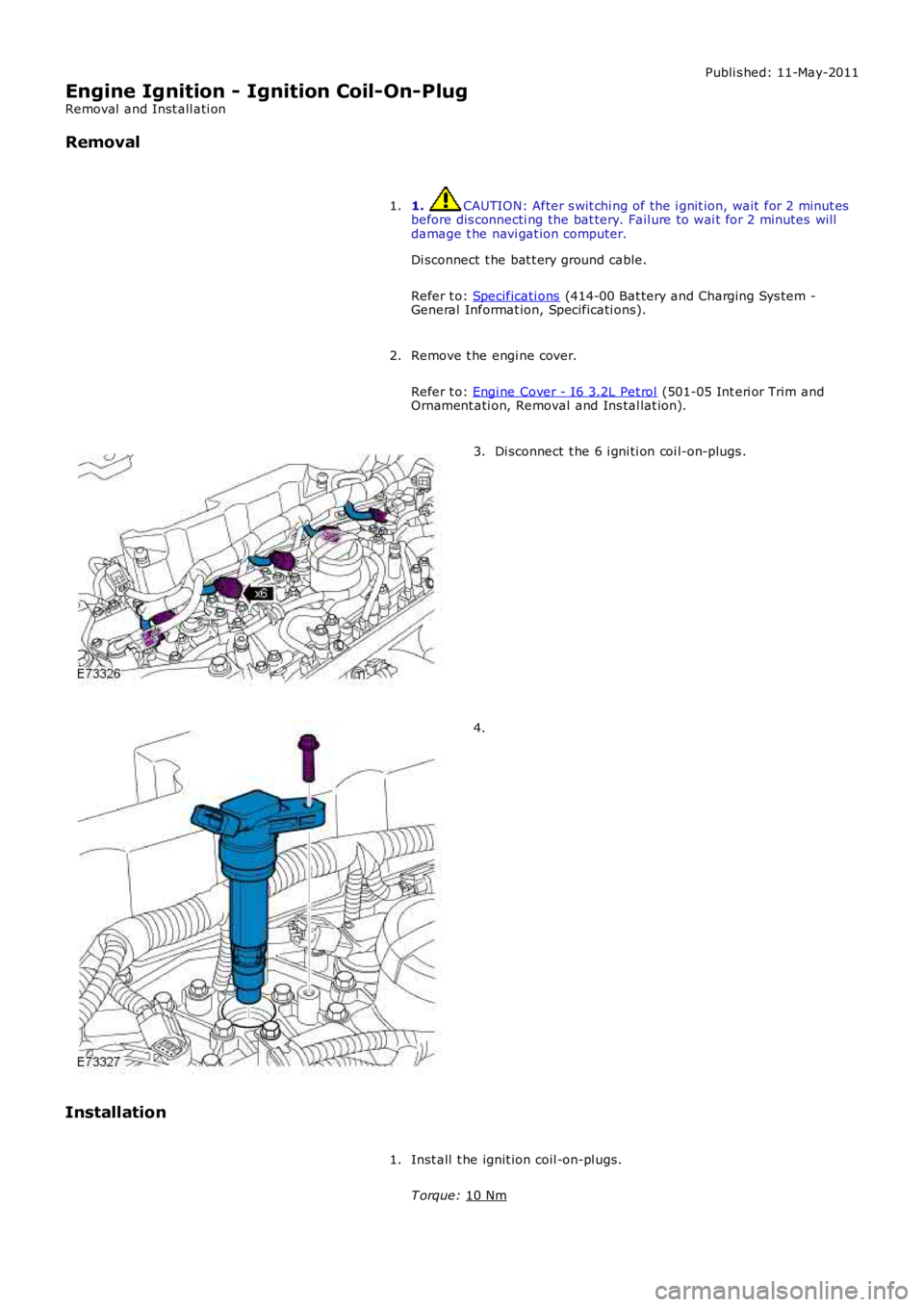
2. Di sconnect t he 6 i gni ti on coi l-on-plugs .
3. 4.
Installation Inst all t he ignit ion coil -on-pl ugs.
T orque: 10 Nm 1.
Page 1120 of 3229
Publi s hed: 11-May-2011
Engine Ignition - Spark Plugs
Removal and Inst all ati on
Removal
1. CAUTION: After s wit chi ng of the i gnit ion, wait for 2 minut es
before dis connecti ng the bat tery. Fail ure to wai t for 2 minutes will
damage t he navi gat ion computer.
Di sconnect t he bat t ery ground cable.
Refer t o: Specificati ons (414-00 Bat tery and Charging Sys tem -
General Informat ion, Specificati ons).
1.
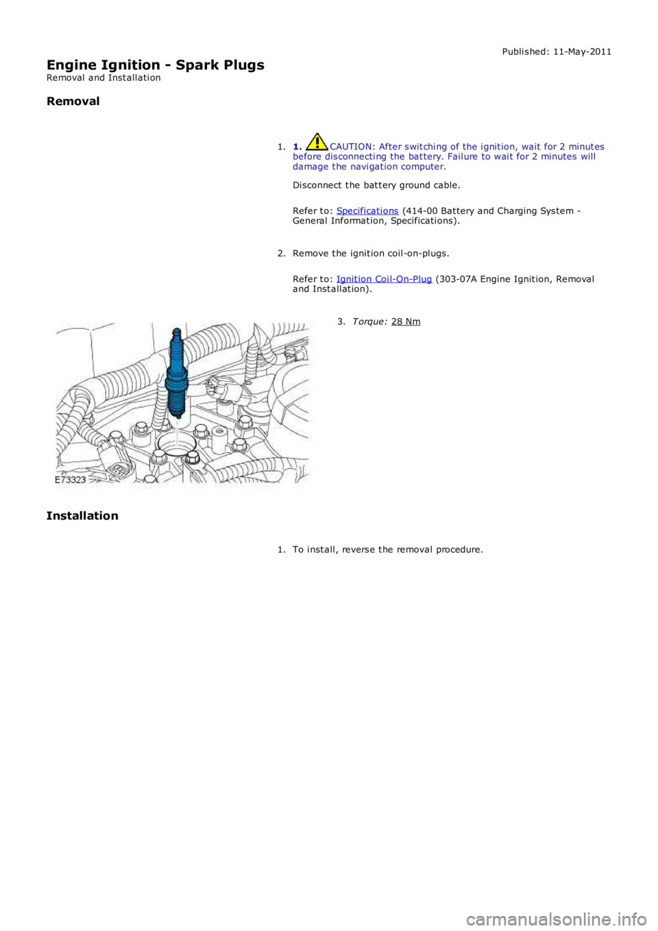
Remove t he ignit ion coil -on-pl ugs.
Refer t o: Ignit ion Coi l-On-Plug (303-07A Engine Ignit ion, Removal
and Inst all at ion).
2. T orque:
28 Nm 3.
Installation To i nst all , revers e t he removal procedure.
1.
Page 1212 of 3229
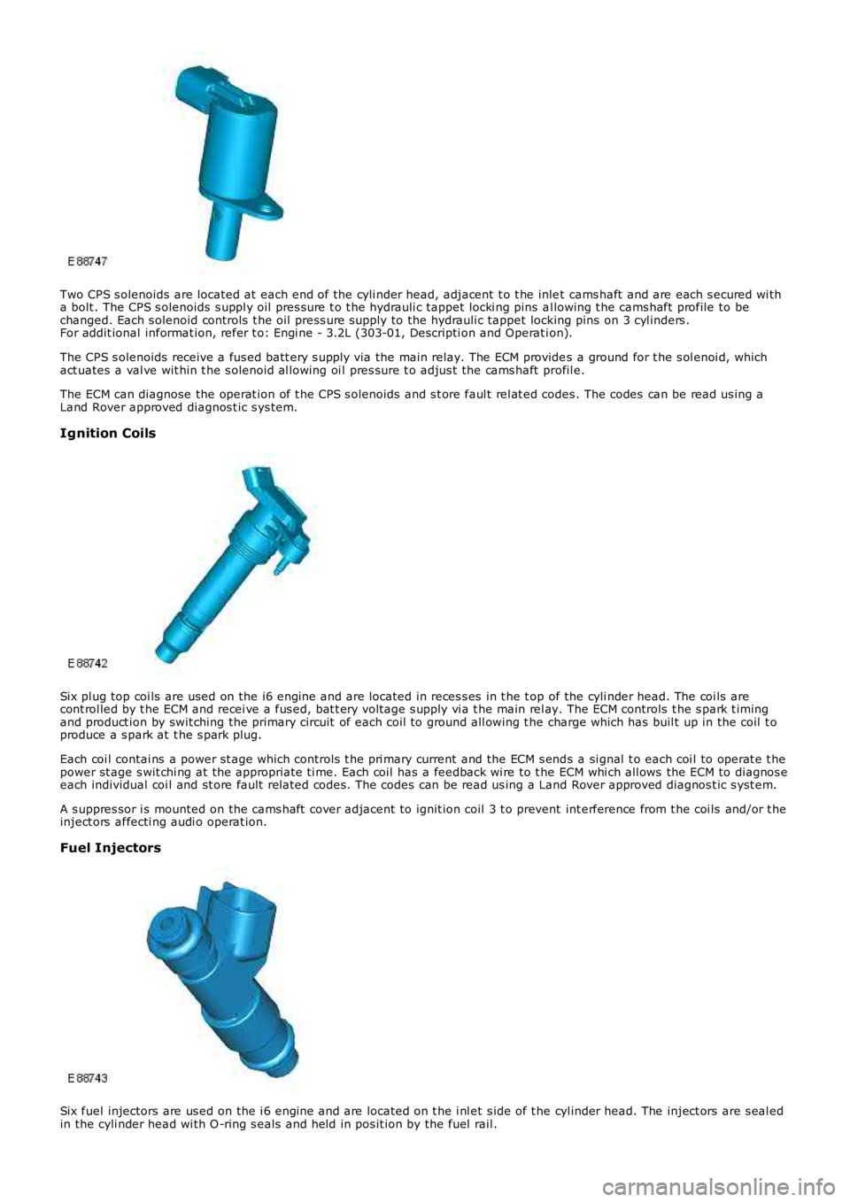
Two CPS s olenoids are located at each end of the cyli nder head, adjacent t o t he inlet cams haft and are each s ecured wi tha bolt . The CPS s olenoids s uppl y oil pres s ure t o t he hydrauli c tappet locki ng pins al lowing t he cams haft profile to bechanged. Each s olenoid controls t he oil press ure supply to the hydrauli c tappet locking pins on 3 cyl inders .For addit ional informat ion, refer t o: Engi ne - 3.2L (303-01, Descripti on and Operat ion).
The CPS s olenoids receive a fus ed batt ery s upply via the main relay. The ECM provides a ground for t he s ol enoi d, whichact uates a val ve wit hin t he s olenoid al lowing oi l pres sure t o adjus t the cams haft profil e.
The ECM can diagnose the operat ion of t he CPS s olenoids and s t ore faul t rel at ed codes . The codes can be read us ing aLand Rover approved diagnos t ic s ys tem.
Ignition Coils
Six pl ug top coi ls are used on the i6 engine and are located in reces s es in t he t op of the cyli nder head. The coi ls arecont rol led by t he ECM and recei ve a fus ed, bat t ery volt age s upply vi a t he main rel ay. The ECM controls t he s park t imingand product ion by swit ching the primary circuit of each coil to ground all owing t he charge which has buil t up in the coil t oproduce a s park at t he s park plug.
Each coi l contai ns a power st age which controls t he pri mary current and the ECM s ends a si gnal t o each coi l to operat e t hepower st age s wit chi ng at the appropriate ti me. Each coil has a feedback wi re to t he ECM whi ch all ows the ECM to diagnos eeach individual coi l and st ore fault related codes. The codes can be read us ing a Land Rover approved diagnos t ic s yst em.
A s uppres sor i s mounted on the cams haft cover adjacent to ignit ion coil 3 t o prevent int erference from t he coi ls and/or t heinject ors affecti ng audi o operat ion.
Fuel Injectors
Six fuel injectors are us ed on the i 6 engine and are located on t he i nl et s ide of t he cyl inder head. The inject ors are s eal edin the cyli nder head wi th O -ring s eals and held in pos it ion by the fuel rail .
Page 1218 of 3229
The posi ti on of the inlet cams haft is det ermi ned by the ECM us ing s ignals from t he CKP s ens or and t he CMP s ens ors. TheECM can t hen use the VCT sol enoid val ve to cont rol t he angl e of the cams haft by controlli ng t he fl ow of oil t o t he VCT unit .
The camshaft is s ecured t o t he rot or in t he VCT unit . Oil pres s ure suppli ed to eit her s ide of t he VCT unit from t he VCTs olenoi d valve can rot ate the rotor and hence the cams haft i n eit her di recti on. The VCT sol enoi d is operat ed by t he ECMus ing PW M, hi gh frequency s wit chi ng which provi des rapid and preci se cont rol of the i nlet cams haft pos i ti on. The i nletcamshaft pos i ti on can be adjust ed wi thi n 40 degrees of cranks haft rotat ion.
Camshaft Profile Switching (CPS) Control
The inl et cams haft has , in addit ion to t he VCT control, a CPS funct ion whi ch is al so cont roll ed by t he ECM. The CPS cont rolcan vary t he val ve li ft height and durat ion of t he camshaft lobes by adjus ti ng the area of t he hydraul ic t appet whi ch act son one of t wo cam l obe profi les . The CPS cont rol is vi a t wo CPS s olenoid valves , located at each end of the i nlet cams haft.The CPS s olenoid valves cont rol t he posi ti on of hydraul ic t appet as s embli es which can be s et in one of t wo pos it ions; lowand high.
Two CPS s olenoids are us ed so that t he hydraul ic t appet s can be adjus t ed when no load i s applied, for example the camlobes are off t he hydraul ic t appet s and t he cam bas e circl e is act ing on t he t appet , thi s keeps t he s tress on components toa minimum. One CPS s ol enoi d s uppl ies oi l press ure to the hydrauli c t appet s of cyli nders 1, 2 and 4 and the s econd CPSs olenoi d s uppl ies oi l press ure to the tappet s of cylinders 3, 5 and 6.
At engi ne s tart and at low engine oi l temperat ures (below 40°C (104°F)) the ECM does not direct engine oi l pres sure t ot he hydraul ic t appet s and t herefore the hydraul ic t appet s are in t heir s pring loaded, l ow posi ti on.For addit ional informat ion, refer t o: Engi ne - 3.2L (303-01, Descripti on and Operat ion).
Ignition Control
The ECM calculat es the opt imum ignit ion ti ming bas ed on pre-programmed maps and informat ion from t he foll owings ens ors :
CKP s ensorCMP s ensorsMAF s ensorECT s ens orElectric t hrot tl e TP s ensorKnock s ens orsTCMIgni ti on coi ls .
Duri ng engi ne s tarti ng the ECM uses a fi xed ignit ion s et ti ng. W hen the engine has s tart ed and the vehicle is bei ng driven,t he ECM adjus ts the i gni ti on t imi ng accordi ngl y us ing ot her paramet ers s uch as engine s peed, l oad and temperat ure.
Once the engi ne has reached i ts normal operati ng temperature, t he ECM moni tors the si gnal s from the knock sens ors . Ifany of the cyli nders produce knocking, the i gnit ion t imi ng for t hat cyli nder wi ll be retarded unt il t he knocking has s t opped.The ignit ion is t hen gradually advanced back t o t he normal t imi ng or unt il t he knocking re-occurs .
The ECM us es informat ion from the TCM t o provide t orque l imi tat ion during t rans mis s ion s hifts . The i gni ti on ti mi ng isadjus ted t o moment ari ly reduce t he engine t orque output t o give a smoot h t rans mis s ion shi ft and reduce l oad on thet ransmis s ion.
Air Conditioning (A/C) Compressor Control
The ECM controls t he operati on of the A/C compres s or and reacts t o reques ts from t he ATC module vi a t he high s peed CANbus. The compres s or is a variable di s pl acement unit and t he ECM controls , via a sol enoi d, t he dis placement of thecompres sor t o adjus t load during cert ain driving condit ions.
Duri ng engi ne s tart-up, movi ng from a s tandst il l and under hard accelerat ion, the ECM s et s t he mi nimum dis placement oft he compress or t o reduce the effect on t he engi ne t orque output. The ECM uses i nformati on from t he ATC module, t he A/Cpres s ure s ensor, the el ect ri c t hrott le TP s ens or and the ECT sens or to det ermi ne compres sor control . The ATC modulet ransmit s climate control and driver reques ts t o t he ECM and t he ECM det ermi nes the priori ty of thes e request s overengi ne performance.
Page 1652 of 3229
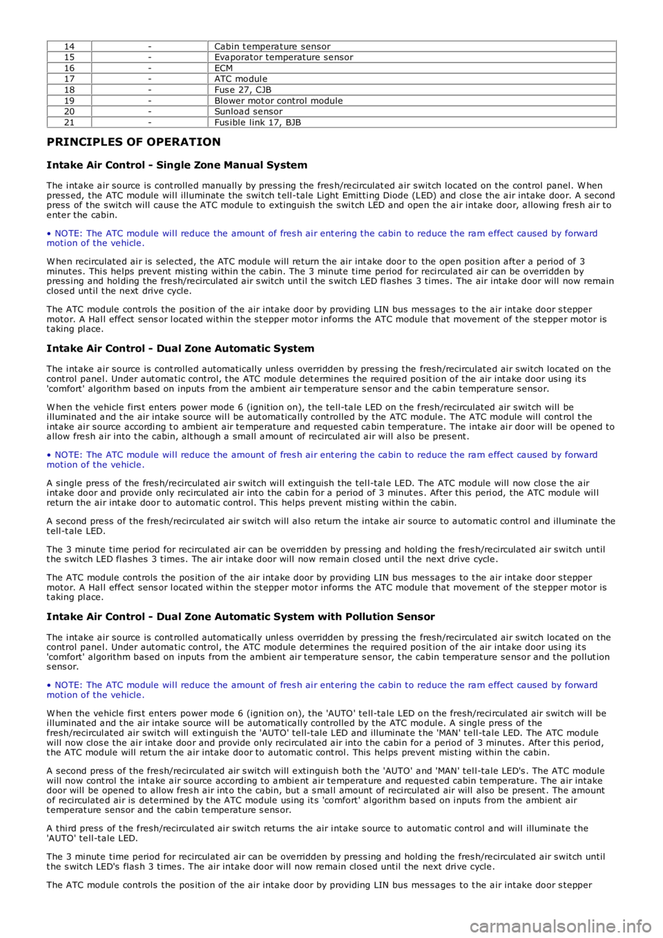
14-Cabin t empera ture sensor15-Eva porator temperature se nsor16-ECM17-ATC modul e18-Fus e 27, CJB19-Blower mot or control module20-Sunloa d se nsor21-Fus ible link 17, BJB
PRINCIPLES OF OPERATION
Intake Air Control - Single Zone Manual System
The i ntake a ir source is cont rolle d manually by press ing the fres h/re circulat ed a ir switch located on the control panel. W he npress ed, the ATC module wil l illuminate the swi tch t ell-tale Light Emitti ng Diode (LED) and clos e the a ir intake door. A secondpress of the swit ch will caus e the ATC module to extinguish the swi tch LED and ope n the a ir intake door, a llowing fres h ai r toe nte r the cabin.
• NO TE: The ATC module wil l reduce the amount of fres h ai r ent ering the ca bin to reduce the ra m e ffect ca used by forwardmoti on of the ve hicle .
W he n recirculate d ai r is sele cted, the ATC module will re turn the air int ake door to the ope n position a fter a pe riod of 3minutes. Thi s he lps prevent mis ting within t he cabin. The 3 minute time pe riod for reci rcula ted air can be overridde n bypress ing and hol ding the fre sh/re circulat ed a ir s witch until t he s witch LED fl ashes 3 times. The air inta ke door will now remainclose d until t he next drive cycle.
The ATC module controls the pos ition of the air inta ke door by providing LIN bus messa ges to t he a ir intake door s teppermotor. A Hal l eff ect sens or l ocat ed withi n the st epper motor inf orms the ATC module that move me nt of the ste ppe r motor ist aking pl ace.
Intake Air Control - Dual Zone Automatic System
The i ntake a ir source is cont rolle d automatically unl ess overridden by press ing the fresh/recirculate d ai r switch loca ted on thecontrol pane l. Under aut oma tic control, t he ATC module det ermi nes the require d position of the air inta ke door usi ng it s'comfort' algorithm based on inputs from the ambient ai r tempe rature s ensor and the ca bin temperature se nsor.
W he n the ve hicle firs t enters power mode 6 (ignition on), the te ll-ta le LED on t he fresh/recirculated air swi tch will bei lluminat ed a nd t he air intake source wil l be aut oma tica lly controlle d by the ATC modul e. The ATC module will cont rol t hei ntake ai r source accordi ng t o ambie nt a ir te mpe rature a nd requeste d ca bin temperature. The intake ai r door will be opene d toa llow fre sh a ir into t he cabin, alt hough a small a mount of re circulat ed a ir will a lso be prese nt.
• NO TE: The ATC module wil l reduce the amount of fres h ai r ent ering the ca bin to reduce the ra m e ffect ca used by forwardmoti on of the ve hicle .
A single pres s of the fres h/re circulat ed a ir s witch wi ll extinguish the tel l-tal e LED. The ATC module will now close t he a iri ntake door a nd provide only recircul ated air into the cabin f or a period of 3 minutes . Af ter this peri od, the ATC module wil lreturn the ai r int ake door to automa tic control. This helps preve nt misti ng withi n the ca bin.
A second pre ss of the fre sh/recircula ted air s wit ch will a lso return the intake air source to a utomati c control and ill uminate thet ell-t ale LED.
The 3 mi nute time period for recircul ated air can be ove rridden by press ing and holding the fres h/re circulate d a ir switch untilt he s witch LED fl ashes 3 times. The air inta ke door will now remain clos ed unti l the next drive cycle .
The ATC module controls the pos ition of the air inta ke door by providing LIN bus messa ges to t he a ir intake door s teppermotor. A Hal l eff ect sens or l ocat ed withi n the st epper motor inf orms the ATC module that move me nt of the ste ppe r motor ist aking pl ace.
Intake Air Control - Dual Zone Automatic System with Pollution Sensor
The i ntake a ir source is cont rolle d automatically unl ess overridden by press ing the fresh/recirculate d ai r switch loca ted on thecontrol pane l. Under aut oma tic control, t he ATC module det ermi nes the require d position of the air inta ke door usi ng it s'comfort' algorithm based on inputs from the ambient ai r tempe rature s ensor, t he cabin temperature se nsor and the pollut ions ens or.
• NO TE: The ATC module wil l reduce the amount of fres h ai r ent ering the ca bin to reduce the ra m e ffect ca used by forwardmoti on of the ve hicle .
W he n the ve hicle firs t enters power mode 6 (ignition on), the 'AUTO ' te ll-ta le LED on the fresh/reci rcul ated air swit ch will bei lluminat ed a nd t he air intake source wil l be aut oma tica lly controlle d by the ATC modul e. A single pres s of thef resh/recircul ated air swi tch will exti ngui sh t he 'AUTO' te ll-t ale LED and illumina te t he 'MAN' te ll-ta le LED. The ATC modulewill now clos e the ai r int ake door and provide only recirculat ed a ir into t he cabi n for a period of 3 minutes. Afte r this period,t he ATC module will return t he a ir intake door to automatic cont rol. This he lps prevent mist ing within t he cabin.
A second pre ss of the fre sh/recircula ted air s wit ch will e xtinguis h both t he 'AUTO' a nd 'MAN' tel l-ta le LED's . The ATC modulewill now cont rol the inta ke a ir source according t o a mbie nt a ir te mperat ure and request ed cabin tempe rature. The a ir intakedoor will be opened to a llow fres h a ir int o the ca bin, but a s mal l amount of reci rcul ated air will also be pre sent . The amountof re circulate d ai r is dete rmi ned by t he ATC module using it s 'comfort' a lgorithm based on i nputs from the ambient airt emperat ure sensor and the cabi n te mpe rature s ens or.
A thi rd press of t he f resh/recirculate d ai r switch returns the air i ntake s ource to aut oma tic cont rol a nd will illumina te the'AUTO' te ll-ta le LED.
The 3 mi nute time period for recircul ated air can be ove rridden by press ing and holding the fres h/re circulate d a ir switch untilt he s witch LED's flas h 3 time s. The air intake door will now remain clos ed until the next dri ve cycle .
The ATC module controls the pos ition of the air inta ke door by providing LIN bus messa ges to t he a ir intake door s tepper