Page 610 of 3229
ItemPart NumberDescription1-Pis t on cooling jet (6 off)Jet s locat ed in the cylinder block s pray oil on t o t he ins ide of t he pis ton t o provide pis t on and pis ton pin lubricat ion and cooling.The oil is dist ribut ed through t he cylinder block, via t he main oil gallery and channels bored in t he block.
Generator
ItemPart NumberDescription1-Rubber s leeve2-GeneratorThe generat or is locat ed at the rear of t he int ake side of t he cylinder block. The generator is driven by the crankshaft gearwheelvia t he auxiliary unit shaft gearwheel and t he auxiliary unit inner shaft gear wheel (s ee gear housing s ect ion for moreinformat ion).
Gear Housing Components
Page 613 of 3229
The intermediat e s haft is us ed to locat e the cams haft drive s haft gear wheel in t he cylinder block. The shaft is journaled wit h adouble conical roller bearing. The auxiliary unit s haft drive gear wheel is in 2 pieces , wit h t he narrow half being s pring tensioned inthe opposit e direct ion t o t he wide half. This feat ure reduces nois e becaus e gear play is eliminat ed. Only t he wide half drives theauxiliary unit's gear wheel. The cams haft chain gear wheel is of t he conventional design.
The s haft is sealed against the exhaust side (i.e. the rear s ide of t he cylinder block) by a s ealing was her. To remove or inst all t hewasher, t he flywheel/flexplate must be removed.
Camshaft Drive O uter Shaft
The cams haft drive outer s haft is journaled at the front end of t he s haft with a double row bearing in t he gear hous ing. Needlebearings are us ed at t he rear end (pulley s ide) against t he auxiliary unit s haft . The camshaft drive out er s haft gear wheel is in 2pieces , a wide and a narrow half t o reduce nois e. The cams haft chain gear wheel is als o locat ed on the s haft and is us ed to drivethe cams hafts chain.
Auxiliary Unit Inner Shaft
The auxiliary unit inner s haft is journaled at t he front end of t he shaft (generator s ide) in t he gear housing with a s ingle rowbearing. Needle bearings are used at the rear end (pulley s ide) against the cams haft drive shaft . There is a pulley at t he rear endof the s haft that drives t he Air Condit ioning (AC) compress or and the power s t eering pump, via a polyvee belt . The shaft als odrives t he generat or at t he front end, via a sleeve connect or.
Thermostat Housing
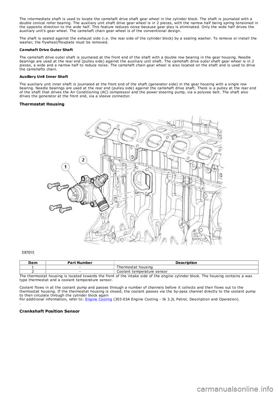
ItemPart NumberDescription1-Thermost at hous ing2-Coolant t emperat ure s ens orThe t hermos tat hous ing is located t owards the front of t he int ake s ide of t he engine cylinder block. The hous ing contains a waxtype t hermost at and a coolant temperat ure sens or.
Coolant flows in at t he coolant pump and pas s es through a number of channels before it collect s and t hen flows out t o t hethermos t at housing. If t he t hermost at hous ing is closed, t he coolant pass es via t he by-pass channel directly to t he coolant pumpto then circulat e t hrough t he cylinder block againFor addit ional information, refer t o: Engine Cooling (303-03A Engine Cooling - I6 3.2L Pet rol, Des cription and Operat ion)..
Crankshaft Position Sensor
Page 630 of 3229
5-Bolt (2 of)6-Variable tract valveThe intake manifold att aches t o t he cylinder head wit h 6 bolt s and t he oil pan with 2 bolt s .
The manifold is capable of varying both int ake tract length and plenum volume by means of 2 separat e valves .
At low engine s peeds , long int ake tract s are ut iliz ed to provide opt imum engine t orque. Short er t racts are us ed at medium s peeds ,again, t o optimiz e engine t orque for t he exist ing engine s peed range.
At higher engine s peeds the benefit s of opt imizing t he t ract lengt hs are outweighed by the necess it y of maintaining anappropriate supply of air to meet t he engines requirement s . Therefore, t he plenum valve is opened t o create a s ingle, largeplenum volume to provide t he maximum quant ity of air t o charge the engines cylinders.For addit ional information, refer t o: Int ake Air Dis tribut ion and Filtering (303-12A Int ake Air Dis t ribution and Filt ering - I6 3.2LPet rol, Des cript ion and O perat ion).
Exhaust Manifold
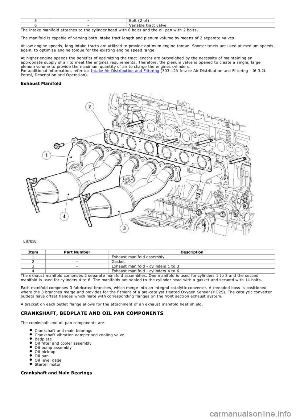
ItemPart NumberDescription1-Exhaus t manifold as sembly2-Gas ket3-Exhaus t manifold - cylinders 1 t o 34-Exhaus t manifold - cylinders 4 t o 6The exhaus t manifold compris es 2 s eparat e manifold as semblies . One manifold is us ed for cylinders 1 t o 3 and t he secondmanifold is us ed for cylinders 4 t o 6. The manifolds are sealed t o the cylinder head wit h a gas ket and s ecured with 14 bolts .
Each manifold comprises 3 fabricat ed branches , which merge int o an int egral cat alyt ic convert er. A t hreaded bos s is posit ionedwhere t he 3 branches merge and provides for t he fit ment of a pre-catalyst Heat ed O xygen Sens or (HO2S). The cat alyt ic convert erout let s have offset flanges which mat e wit h corresponding flanges on t he front s ect ion exhaust s ys t em.
A bracket on each out let flange allows for t he at t achment of an exhaus t manifold heat shield.
CRANKSHAFT, BEDPLATE AND OIL PAN COMPONENTS
The crankshaft and oil pan components are:
Cranks haft and main bearingsCranks haft vibrat ion damper and cooling valveBedplat eO il filter and cooler ass emblyO il pump ass emblyO il pick-upO il panO il level gageSt art er mot or
Crankshaft and Main Bearings
Page 632 of 3229
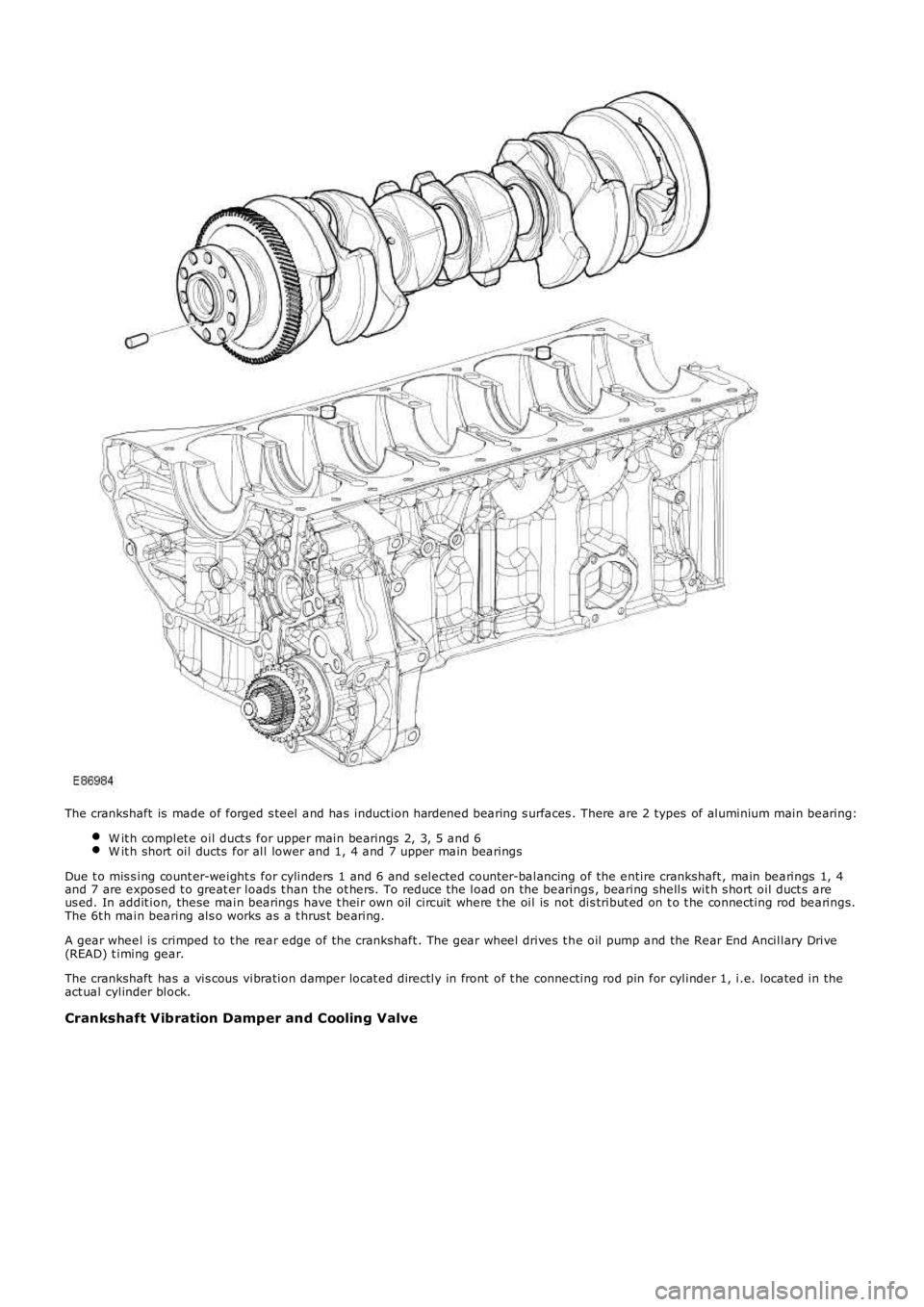
The crankshaft is made of forged s teel and has induction hardened bearing s urfaces . There are 2 types of aluminium main bearing:
W it h complet e oil duct s for upper main bearings 2, 3, 5 and 6W it h short oil ducts for all lower and 1, 4 and 7 upper main bearings
Due t o mis s ing count er-weight s for cylinders 1 and 6 and s elected count er-balancing of the entire crankshaft , main bearings 1, 4and 7 are exposed t o great er loads t han the ot hers. To reduce t he load on the bearings , bearing shells wit h s hort oil duct s areus ed. In addit ion, these main bearings have t heir own oil circuit where t he oil is not dis tribut ed on t o t he connecting rod bearings.The 6t h main bearing als o works as a t hrus t bearing.
A gear wheel is crimped to t he rear edge of the crankshaft . The gear wheel drives t he oil pump and the Rear End Ancillary Drive(READ) t iming gear.
The crankshaft has a vis cous vibration damper locat ed directly in front of t he connecting rod pin for cylinder 1, i.e. located in theact ual cylinder block.
Crankshaft Vibration Damper and Cooling Valve
Page 633 of 3229
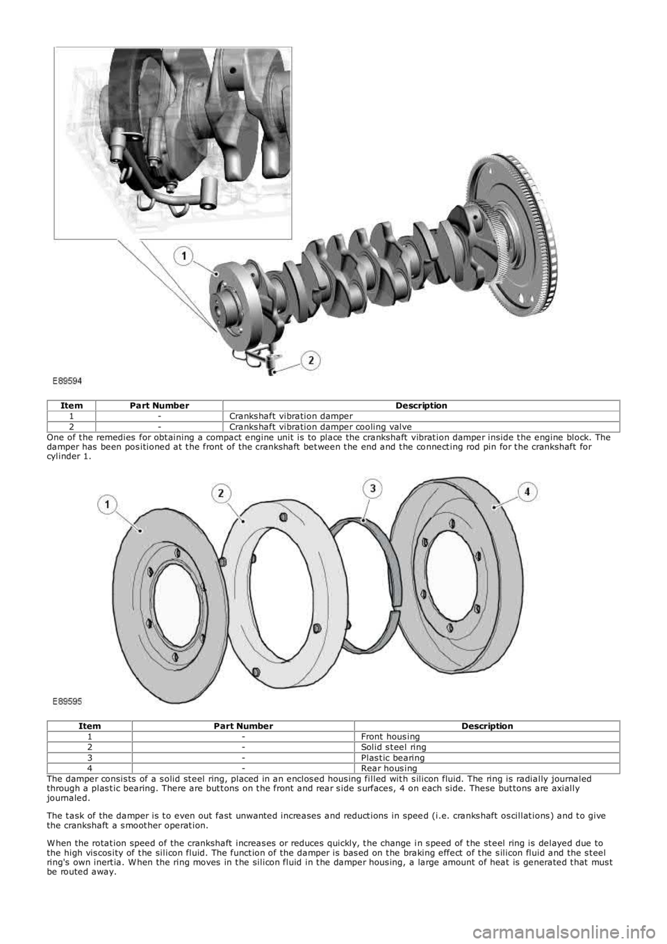
ItemPart NumberDescription1-Cranks haft vibration damper2-Cranks haft vibration damper cooling valveOne of t he remedies for obt aining a compact engine unit is to place the crankshaft vibrat ion damper inside t he engine block. Thedamper has been pos itioned at t he front of the crankshaft bet ween t he end and t he connect ing rod pin for t he crankshaft forcylinder 1.
ItemPart NumberDescription1-Front hous ing2-Solid s t eel ring3-Plas t ic bearing4-Rear hous ingThe damper consis ts of a s olid st eel ring, placed in an enclos ed hous ing filled wit h s ilicon fluid. The ring is radially journaledthrough a plas t ic bearing. There are but t ons on t he front and rear s ide s urfaces, 4 on each side. These but tons are axiallyjournaled.
The t ask of the damper is t o even out fast unwanted increases and reduct ions in speed (i.e. cranks haft os cillat ions ) and t o givethe crankshaft a s moot her operat ion.
W hen the rotat ion speed of the crankshaft increas es or reduces quickly, t he change in s peed of t he st eel ring is delayed due tothe high vis cos ity of t he silicon fluid. The funct ion of the damper is bas ed on t he braking effect of t he s ilicon fluid and the s t eelring's own inert ia. W hen the ring moves in t he silicon fluid in t he damper hous ing, a large amount of heat is generated t hat mus tbe routed away.
Page 634 of 3229
ItemPart NumberDescription1-ValveBecause the damper is locat ed in an environment where t he normal operat ing temperat ure can reach approximat ely 140°C (284°F),coupled wit h t he fact that t he damper also generates it s own heat, it is neces sary for it t o be oil cooled. A s eparat e oil circuitroutes oil from the engine's oil cooler t o a valve in t he engine block, which opens at approximat ely 2 bar. The oil t hen flows t o 3jet s, located on t he cranks haft vibrat ion damper cooling pipe, which then directs the oil t o the lower s ect ion of t he damper.
The oil flows t hrough the jets at approximately 12 lit ers per minute.
At high t emperat ures , oil cooling reduces t he damper t emperat ure by approximat ely 7°C (45°F).
Bedplate
Page 641 of 3229
The s t art er mot or is located in a recess at t he rear of t he exhaus t s ide of t he oil pan. The motor, rated at 1.4 kW , uses permanentmagnet s ins tead of field windings to provide a low-weight st arter motor; wit h the use of planet ary gears t o deliver a good t orqueto weight ratioFor addit ional information, refer t o: Start ing Syst em (303-06A St art ing Sys t em - I6 3.2L Petrol, Des cript ion and Operat ion)..
CAMSHAFT TIMING COMPONENTS
ItemPart NumberDescription1-Exhaust cams haft2-Intake cams haft3-Vacuum pump4-Cooling pump housing5-Chain guide
Page 643 of 3229
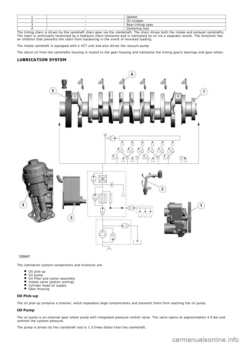
1-Gasket2-Oil s craper3-Rear t iming cas e4-Cent ering t oolThe t iming chain is driven by t he camshaft chain gear via t he cranks haft . The chain drives bot h t he int ake and exhaus t cams haft s.The chain is cont inually t ensioned by a hydraulic chain t ens ioner and is lubricated by oil via a separat e nozz le. The tensioner hasan inhibit or that prevent s t he chain from s lackening in t he event of revers ed loading.
The intake camshaft is equipped wit h a VCT unit and als o drives t he vacuum pump.
The return oil from t he cams hafts housing is rout ed t o t he gear hous ing and lubricates t he timing gear's bearings and gear wheel.
LUBRICATION SYSTEM
The lubricat ion sys tem component s and funct ions are:
O il pick-upO il pumpO il filter and cooler ass emblyIntake valve (pis t on cooling)Cylinder head oil supplyGear hous ing
Oil Pick-up
The oil pick-up contains a s t rainer, which s eparat es large cont aminant s and prevent s t hem from reaching t he oil pump.
Oil Pump
The oil pump is an external gear wheel pump wit h int egrat ed pres sure cont rol valve. The valve opens at approximat ely 4.5 bar andcont rols t he sys tem pres sure.
The pump is driven by t he cranks haft and is 1.3 t imes fast er t han t he crankshaft .