2006 LAND ROVER FRELANDER 2 check transmission fluid
[x] Cancel search: check transmission fluidPage 1303 of 3229
Publi s hed: 11-May-2011
Automatic Transmission/Transaxle - Transmission Fluid Level CheckTD4
2.2L Diesel
General Procedures W ARNING: Observe due care when drai ning, as the flui d can be very hot .
Ens ure t hat the aut omat ic trans mi s si on is in 'P' and t he handbrake is
ful ly appli ed.
1.
Clean t he area around the trans mi s si on fl uid fil ler plug.
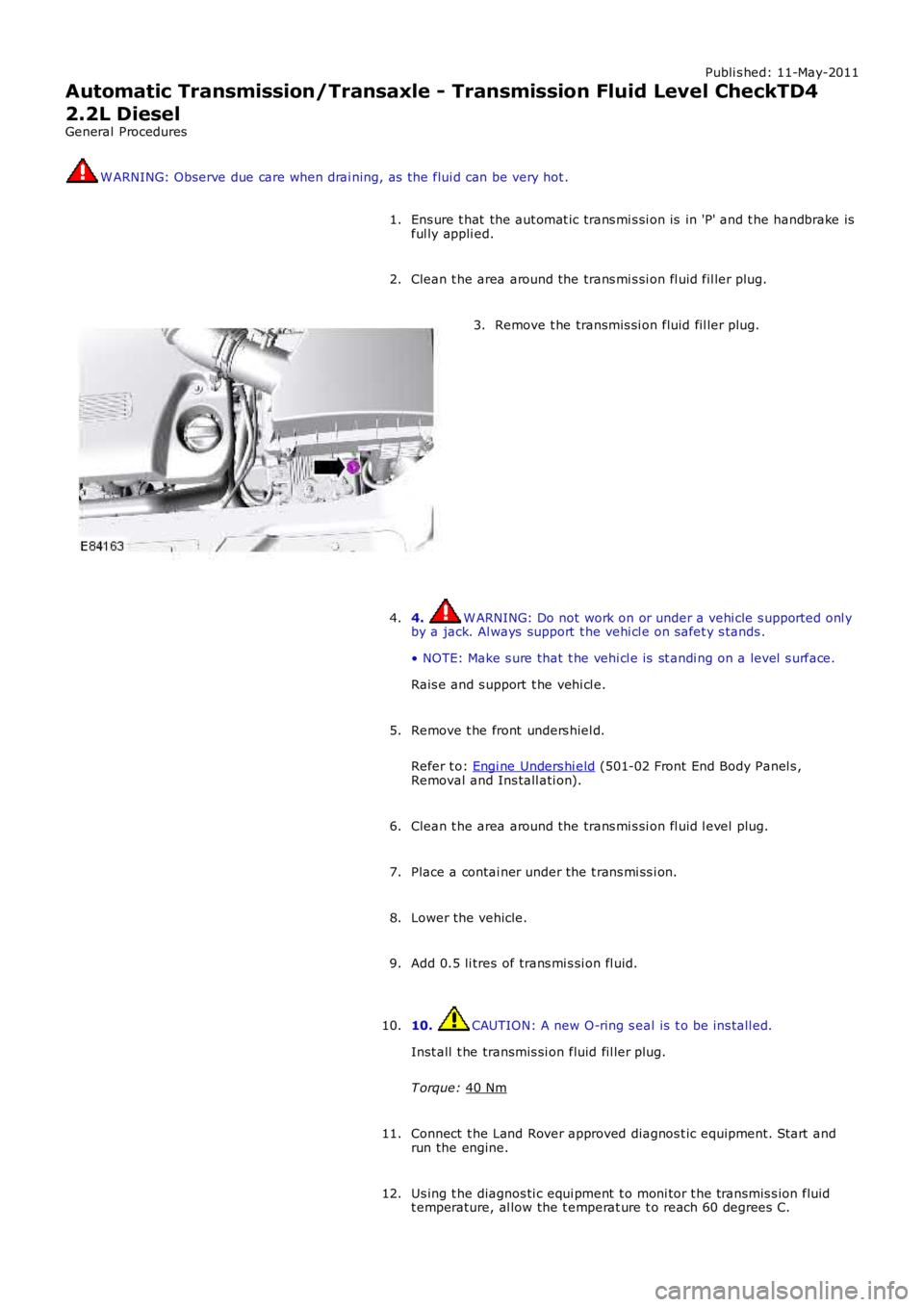
2. Remove t he transmis si on fluid fil ler plug.
3.
4. W ARNING: Do not work on or under a vehi cle s upported onl y
by a jack. Al ways support t he vehi cl e on s afet y s tands .
• NOTE: Make s ure that t he vehi cl e is st andi ng on a level s urface.
Rais e and s upport t he vehi cl e.
4.
Remove t he front unders hiel d.
Refer t o: Engi ne Unders hi eld (501-02 Front End Body Panel s ,
Removal and Ins tall ati on).
5.
Clean t he area around the trans mi s si on fl uid l evel plug.
6.
Place a contai ner under the t rans mi ss i on.
7.
Lower the vehicle.
8.
Add 0.5 li tres of trans mi s si on fl uid.
9.
10. CAUTION: A new O-ring s eal is t o be ins tall ed.
Inst all t he transmis si on fluid fil ler plug.
T orque: 40 Nm 10.
Connect t he Land Rover approved diagnos t ic equipment. St art and
run the engine.
11.
Us ing t he diagnos ti c equi pment t o moni tor t he transmis s ion fluid
t emperature, al low the t emperat ure t o reach 60 degrees C.
12.
Page 1361 of 3229
Publi s hed: 11-May-2011
Transmission/Transaxle Cooling - Transmission Cooling
Diagnosi s and Tes ti ng
Principles of Operation
For a detail ed descripti on of the aut omati c transmis s ion cool ing s ys tem, refer t o t he relevant Descripti on and Operat ions ect ion i n t he works hop manual .REFER to: Trans mi ss i on Cool ing (307-02 Trans mi ss ion/Transaxle Cool ing, Descripti on and Operat ion).
Inspection and Verification
1. Verify t he cus t omer concern.1.
2. Vis ually ins pect for s ys tem int egrit y and obvi ous s igns of mechanical damage.2.
Visual Inspection
Mechanical
Feed and ret urn t ubesConnect ions t o the aut omati c t ransmis s ion and t he automat ic t rans mis s ion flui d cool erAutomat ic trans mi ss i on fl uid l evel
3. If an obvious cause for an obs erved or report ed concern is found, correct t he caus e (if pos s ible) beforeproceeding t o t he next s t ep3.
4. If t he caus e is not vis ually evi dent , verify t he sympt om and refer t o t he Sympt om Chart.4.
Symptom Chart
ConditionPossible CauseAction
Over heat ing of t heautomat ict rans mis s ion
Obs truct ion i n t he automat ict rans mis s ion fluid cool erFl us h out t he automat ic t rans mi ss ion fl ui d cool er wit hnew aut omati c t rans mis s ion fluidIf t he fl ushi ng is uns ucces sful, ins t al l a new cooler.REFER t o: Transmis s ion Flui d Cooler - I6 3.2L Petrol(307-02 Trans mi ss i on/Trans axl e Cooling, Removal andIns tall ati on) /Trans mi s si on Fluid Cool er - TD4 2.2L Di es el (307-02Trans mi s si on/Trans axl e Cooli ng, Removal andIns tall ati on).
Over heat ing of t heautomat ict rans mis s ion
Obs truct ion i n t he automat ict rans mis s ion fluid tubesFl us h out t he automat ic t rans mi ss ion fl ui d cool er tubeswit h new automat ic t rans mi ss i on fl ui dIf t he fl ushi ng is uns ucces sful ins tall new aut omati ct rans mi ss i on fl ui d cooler tubes
Loss of aut omati ct rans mis s ion flui dConnect ions to the aut omati ct rans mis s ion and t he automat ict rans mis s ion fluid cool er
Check t he int egrit y of tubes , connect ions and s ealsCheck t he torque of t he t ube fi xi ngs.REFER t o: Specificati ons (307-02Trans mi s si on/Trans axl e Cooli ng, Speci fi cat ions ).
Loss of aut omati ct rans mis s ion flui dLeak at aut omati c t ransmis s ion fluidcool erCheck t he int egrit y of tubes , connect ions and s ealsCheck t he torque of t he t ube fi xi ngs.REFER t o: Specificati ons (307-02Trans mi s si on/Trans axl e Cooli ng, Speci fi cat ions ).Check for aut omat ic trans mi s si on fl uid contami nat ionof t he engine cool ant. Inst all new cooler as required.REFER t o: Transmis s ion Flui d Cooler - I6 3.2L Petrol(307-02 Trans mi ss i on/Trans axl e Cooling, Removal andIns tall ati on) /Trans mi s si on Fluid Cool er - TD4 2.2L Di es el (307-02Trans mi s si on/Trans axl e Cooli ng, Removal andIns tall ati on).
Page 1405 of 3229
Publi s hed: 11-May-2011
Manual Transmission/Transaxle and Clutch - General Information - Clutch
System Bleeding
General Procedures
Check that all t he clutch l ine connect ions are ti ght and t hat thereare no s igns of leaks.1.
2.
3. W ARNING: Do not allow dirt or forei gn li qui ds to ent er theres ervoi r. Us e only new brake fl uid of t he correct s peci fi cat ion fromairti ght cont ai ners . Do not mix brands of brake fl uid as t hey may notbe compati ble.
CAUTION: Brake fl ui d wi ll damage paint fi nis hed s urfaces. Ifs pil led, immedi at ely remove t he fl uid and clean t he area wit h wat er.
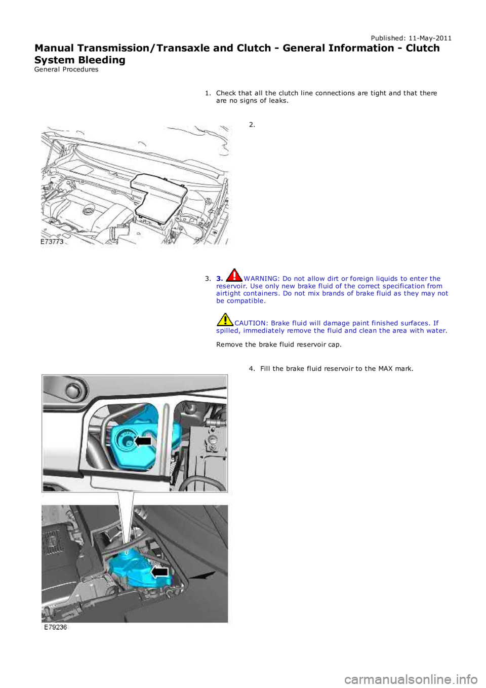
Remove t he brake fluid res ervoir cap.
3.
Fil l the brake fl ui d res ervoi r to t he MAX mark.4.
Page 1432 of 3229
Publi s hed: 11-May-2011
Manual Transmission/Transaxle - Transmission Fluid Level Check
General Procedures W ARNING: Observe due care when drai ning, as the flui d can be very hot .
1. W ARNING: Do not work on or under a vehi cle s upported onl y
by a jack. Al ways support t he vehi cl e on s afet y s tands .
• NOTE: Make s ure that t he vehi cl e is st andi ng on a level s urface.
Rais e and s upport t he vehi cl e.
1.
Remove t he front unders hiel d.
Refer t o: Engi ne Unders hi eld (501-02 Front End Body Panel s ,
Removal and Ins tall ati on).
2.
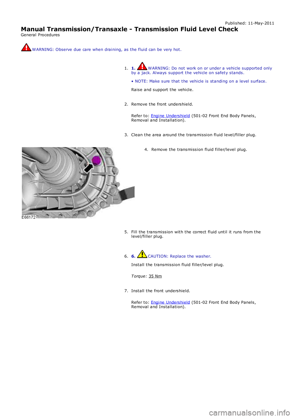
Clean t he area around the trans mi s si on fl uid l evel /fil ler plug.
3. Remove the trans mi ss i on fl uid fil ler/level plug.
4.
Fil l the t rans mi ss ion wit h t he correct fl uid unt il it runs from t he
l evel/fi ll er pl ug.
5.
6. CAUTION: Replace t he washer.
Inst all t he transmis si on fluid fil ler/l evel plug.
T orque: 35 Nm 6.
Inst all t he front unders hiel d.
Refer t o: Engi ne Unders hi eld (501-02 Front End Body Panel s ,
Removal and Ins tall ati on).
7.
Page 1772 of 3229
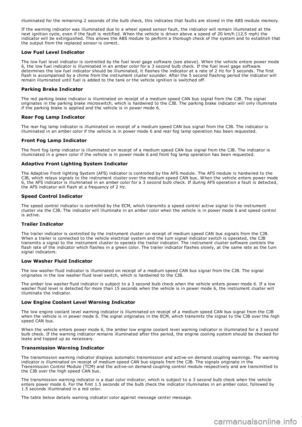
il lumi nat ed for t he remaining 2 s econds of the bulb check, this indicates t hat faults are st ored in t he ABS module memory.
If the warning i ndi cat or was il luminat ed due to a wheel speed s ensor faul t, t he i ndicat or will remain ill uminat ed at thenext i gnit ion cycl e, even i f the fault is recti fi ed. W hen the vehicle is driven above a s peed of 20 km/h (12.5 mph) theindicat or wi ll be ext ingui s hed. This al lows t he ABS module to perform a thorough check of t he s yst em and to es t abl is h t hatt he out put from t he repl aced s ensor i s correct .
Low Fuel Level Indicator
The low fuel level indicator is cont roll ed by t he fuel level gage s oftware (s ee above). W hen t he vehicle ent ers power mode6, the low fuel i ndicat or is ill uminat ed in an amber color for a 3 s econd bulb check. If t he fuel level gage softwaredetermines t he low fuel indicator s houl d be i ll uminated, it flas hes t he indicator at a rate of 2 Hz for 5 seconds . The firstfl ash is accompani ed by a chime from t he ins t rument clus ter s ounder. After t he 5 s econd fl as hing period t he indi cat or willremai n i llumi nated unt il fuel is added t o t he t ank or t he vehi cle i gni ti on is swi tched off.
Parking Brake Indicator
The red parking brake i ndi cat or is i ll uminated on receipt of a medium s peed CAN bus s ignal from t he CJB. The s ignalori ginates i n t he parking brake micros wit ch, whi ch is hardwired to the CJB. The parking brake indicator wil l onl y i llumi nateif t he parking brake is appli ed and t he vehi cl e is in power mode 6.
Rear Fog Lamp Indicator
The rear fog lamp indicator is il luminat ed on receipt of a medi um s peed CAN bus s ignal from t he CJB. The i ndicat or isil lumi nat ed i n an amber col or if t he vehi cl e is in power mode 6 and rear fog l amp operat ion has been reques ted.
Front Fog Lamp Indicator
The front fog l amp i ndi cat or is i ll uminated on recei pt of a medium s peed CAN bus si gnal from the CJB. The indi cat or i sil lumi nat ed i n a green color i f the vehicle is i n power mode 6 and front fog lamp operat ion has been reques ted.
Adaptive Front Lighting System Indicator
The Adapt ive Front l ight ing Syst em (AFS) indicator i s cont rol led by t he AFS module. The AFS module i s hardwi red t o t heCJB, whi ch relays s ignals to the i nst rument clus ter over the medi um s peed CAN bus . When t he vehi cl e enters power mode6, the AFS indicator is ill uminat ed in an amber color for a 3 s econd bul b check. If duri ng AFS operati on a faul t is det ect ed,t he AFS indicator wi ll fl ash at a frequency of 2 Hz.
Speed Control Indicator
The s peed control indicator i s cont roll ed by t he ECM, which t rans mit s a s peed cont rol acti ve si gnal t o t he ins t rumentclus ter via the CJB. The indicator wi ll il lumi nat e i n an amber col or when the vehicle is i n power mode 6 and s peed cont rolis act ive.
Trailer Indicator
The t rail er indicator is cont roll ed by t he ins trument cl ust er on receipt of medium speed CAN bus si gnal s from the CJB.W hen a trailer i s connected t o t he vehi cle el ect ri cal s ys t em and t he t urn s i gnal indicat or s wi tch i s operated, t he CJBt ransmit s a s ignal to the ins trument cl us t er to operat e t he t rail er indicator. The inst rument clus t er s oftware cont rol s thefl ash rat e of the indicator which flas hes in a green color. The t rai ler indi cat or flas hes s lowly, at t he s ame rat e as t he t urns ignal indicators .
Low Washer Fluid Indicator
The low washer fluid indicator is il luminat ed on receipt of a medi um s peed CAN bus signal from t he CJB. The s i gnalori ginates i n t he low washer fl uid l evel s wit ch, whi ch is hardwired to the CJB.
The amber low was her fl uid i ndi cat or is s ubject t o a 3 second bul b check when the vehicle ent ers power mode 6. If a lowwas her fluid level is detect ed for more t han 15 seconds when the vehicle is i n power mode 6, the ins trument cl us t er wil lil lumi nat e t he indi cat or.
Low Engine Coolant Level Warning Ind icator
The low engi ne cool ant l evel warni ng indicat or i s il lumi nat ed on recei pt of a medium speed CAN bus s i gnal from the CJBwhen t he vehi cl e is in power mode 6. The s ignal origi nat es in the ECM, whi ch trans mits the s i gnal t o t he CJB over t he highs peed CAN bus.
W hen t he vehicle ent ers power mode 6, the amber l ow engine coolant level warning i ndi cat or is i ll uminated for a 3 secondbulb check. If the warning i ndi cat or remai ns ill uminat ed aft er this period, the engine cooli ng s yst em s hould be checked forleaks and t opped up as necess ary.
Transmission Warning Indicator
The t ransmis s ion warni ng indi cat or di spl ays aut omati c transmis s ion and acti ve-on demand coupli ng warni ngs . The warni ngindicat or i s il lumi nat ed on recei pt of medi um s peed CAN bus s ignals from t he CJB. The s ignals origi nat e i n theTrans mis s ion Cont rol Modul e (TCM) and the act ive-on demand coupl ing control modul e res pect ively and are t rans mi tt ed tot he CJB over t he high s peed CAN bus .
The t ransmis s ion warni ng indi cat or i s a dual col or indicator, whi ch is subject t o a 3 second bulb check when the vehicleenters power mode 6. For t he fi rs t 1.5 seconds of the bulb check t he indicator i llumi nates i n an amber col or, fol lowed by1.5 seconds ill uminat ed in a red color.
The t abl e below det ails warning i ndicat or col or agai ns t mes s age cent er mess age.
Page 2741 of 3229
21
Quick start
R
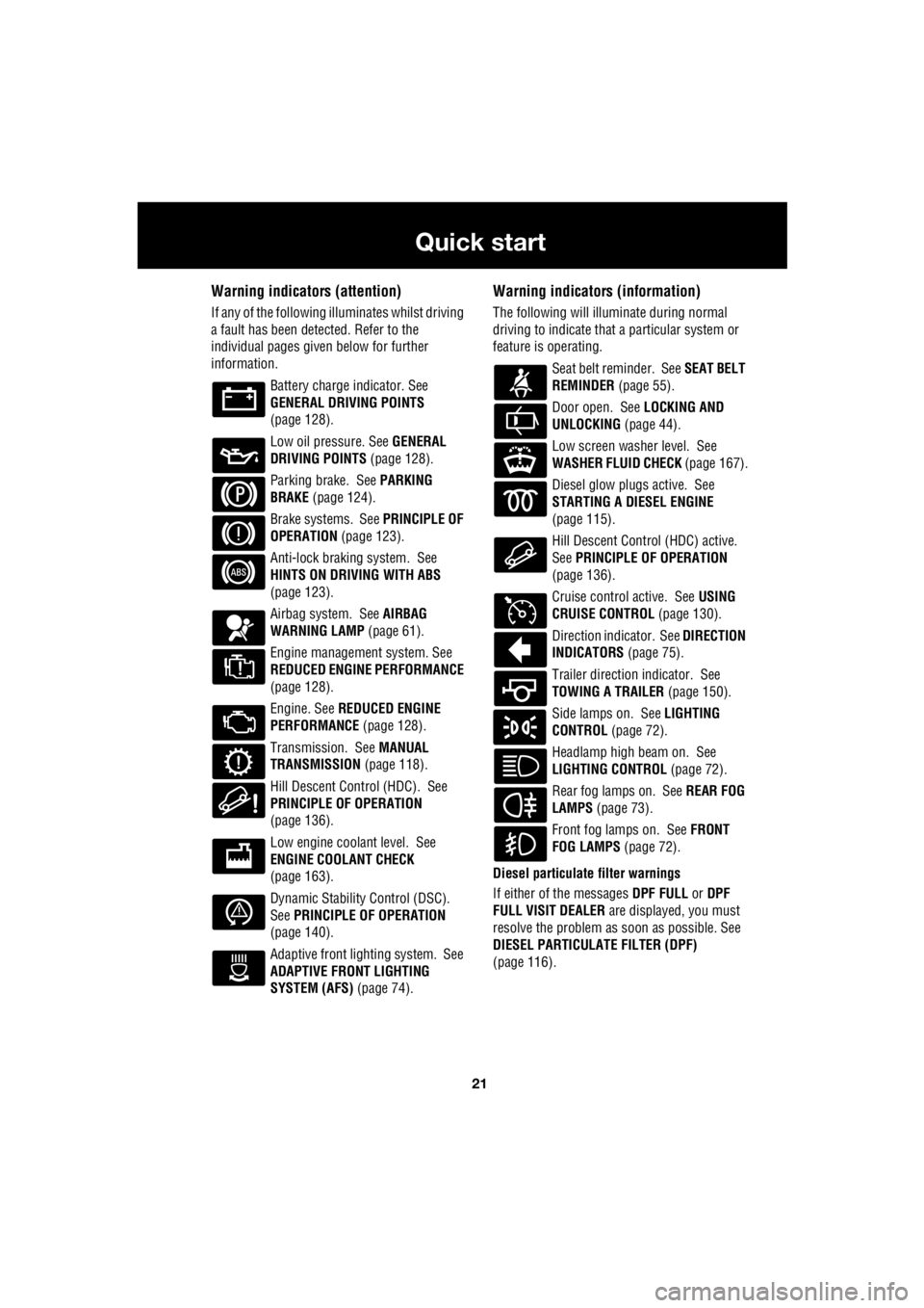
Warning indicators (attention)
If any of the following illuminates whilst driving
a fault has been detected. Refer to the
individual pages give n below for further
information.
Battery charge indicator. See
GENERAL DRIVING POINTS
(page 128).
Low oil pressure. See GENERAL
DRIVING POINTS (page 128).
Parking brake. See PARKING
BRAKE (page 124).
Brake systems. See PRINCIPLE OF
OPERATION (page 123).
Anti-lock braking system. See
HINTS ON DRIVING WITH ABS
(page 123).
Airbag system. See AIRBAG
WARNING LAMP (page 61).
Engine management system. See
REDUCED ENGINE PERFORMANCE
(page 128).
Engine. See REDUCED ENGINE
PERFORMANCE (page 128).
Transmission. See MANUAL
TRANSMISSION (page 118).
Hill Descent Control (HDC). See
PRINCIPLE OF OPERATION
(page 136).
Low engine coolant level. See
ENGINE COOLANT CHECK
(page 163).
Dynamic Stability Control (DSC).
See PRINCIPLE OF OPERATION
(page 140).
Adaptive front lighting system. See
ADAPTIVE FRONT LIGHTING
SYSTEM (AFS) (page 74).
Warning indicators (information)
The following will illuminate during normal
driving to indicate that a particular system or
feature is operating.
Seat belt reminder. See SEAT BELT
REMINDER (page 55).
Door open. See LOCKING AND
UNLOCKING (page 44).
Low screen washer level. See
WASHER FLUID CHECK (page 167).
Diesel glow plugs active. See
STARTING A DIESEL ENGINE
(page 115).
Hill Descent Control (HDC) active.
See PRINCIPLE OF OPERATION
(page 136).
Cruise control active. See USING
CRUISE CONTROL (page 130).
Direction indicator. See DIRECTION
INDICATORS (page 75).
Trailer direction indicator. See
TOWING A TRAILER (page 150).
Side lamps on. See LIGHTING
CONTROL (page 72).
Headlamp high beam on. See
LIGHTING CONTROL (page 72).
Rear fog lamps on. See REAR FOG
LAMPS (page 73).
Front fog lamps on. See FRONT
FOG LAMPS (page 72).
Diesel particulate filter warnings
If either of the messages DPF FULL or DPF
FULL VISIT DEALER are displayed, you must
resolve the problem as soon as possible. See
DIESEL PARTICULATE FILTER (DPF)
(page 116).
Page 2991 of 3229

Index
271
R
A
ABS driving hints . . . . . . . . . . . . . . . . . . 123
Accessories . . . . . . . . . . . . . . . . . . . . . . . . 37
Adaptive front lighting system (AFS). . . . . 74
Adjusting the headlamps . . . . . . . . . . . . . . 73
Adjusting the steering wheel . . . . . . . . . . . 70
Adjusting the windscreen washer jets . . . . 89 Blocked jets . . . . . . . . . . . . . . . . . . . . . 90
Front . . . . . . . . . . . . . . . . . . . . . . . . . . . 89
Rear . . . . . . . . . . . . . . . . . . . . . . . . . . . 89
AFS . . . . . . . . . . . . . . . . . . . . . . . . . . . . . . 74
Air vents . . . . . . . . . . . . . . . . . . . . . . . . . 101
Airbag service information . . . . . . . . . . . . 63
Airbag warning lamp . . . . . . . . . . . . . . . . . 61
Alternative frequencies . . . . . . . . . . . . . . 229
Alternative Frequency (AF) - Premium audio 230
Alternative Frequency (A F) - Standard audio
230
Approach lamps . . . . . . . . . . . . . . . . . . . . 76
Arming the alarm . . . . . . . . . . . . . . . . . . . 45
Alarm indicator . . . . . . . . . . . . . . . . . . . 45
Full alarm . . . . . . . . . . . . . . . . . . . . . . . 45
Partial alarm . . . . . . . . . . . . . . . . . . . . . 45
Ashtray . . . . . . . . . . . . . . . . . . . . . . . . . . 109
Audio control. . . . . . . . . . . . . . . . . . . 70, 223 Audio control using the telephone buttons .
71
Balance adjustment. . . . . . . . . . . . . . . 224
Bass response adjustment . . . . . . . . . 223
Centre speaker settings . . . . . . . . . . . 224
Fader adjustment . . . . . . . . . . . . . . . . 224
Resetting tone values . . . . . . . . . . . . . 224
Subwoofer settings . . . . . . . . . . . . . . . 224
Surround sound settings . . . . . . . . . . 223
Treble response adjustment . . . . . . . . 223
Audio controls . . . . . . . . . . . . . . . . . . . . . 235
Audio unit overview. . . . . . . . . . . . . . . . . 219 Basic audio functions . . . . . . . . . . . . . 222
Premium audio overview . . . . . . . . . . 219
Standard audio overview . . . . . . . . . . 221
Automatic climate control . . . . . . . . . . . . 103
Controls . . . . . . . . . . . . . . . . . . . . . . . 103 Automatic transmission . . . . . . . . . . . . . . 118
Automatic mode. . . . . . . . . . . . . . . . . . 119
Electronic gear change strategies . . . . 120
Sport mode and CommandShift™ . . . . 120
Autostore control . . . . . . . . . . . . . . . . . . . 225 Autostoring radio stat ions - Premium audio
225
Autostoring radio stati ons - Standard audio
225
Auxiliary heater. . . . . . . . . . . . . . . . . . . . . 104
Auxiliary input (AUX IN) socket . . . . . . . . 250 Auxiliary mode . . . . . . . . . . . . . . . . . . . 251
Auxiliary power sockets . . . . . . . . . . . . . . 110
B
Battery care . . . . . . . . . . . . . . . . . . . . . . . 171
Battery charging . . . . . . . . . . . . . . . . . . . . 174
Battery warning symbols . . . . . . . . . . . . . 171
Bluetooth setup . . . . . . . . . . . . . . . . . . . . 256
Adding or changing a telephone. . . . . . 257
Loss of Bluetooth link . . . . . . . . . . . . . 257
Pairing a telephone to the system . . . . 256
Removing a telephone fr om the system. . .
257
Bonnet lock . . . . . . . . . . . . . . . . . . . . . . . 160
Booster cables . . . . . . . . . . . . . . . . . . . . . 173
Booster cushions . . . . . . . . . . . . . . . . . . . . 66
Brake and clutch fluid check . . . . . . . . . . . 165
Checking the fluid level . . . . . . . . . . . . 165
Topping up the fluid . . . . . . . . . . . . . . . 166
Brakes
Principle of operation . . . . . . . . . . . . . . 123
Bulb changing . . . . . . . . . . . . . . . . . . . . . . 77
Bulb specification chart . . . . . . . . . . . . . . . 86
C
Car wash . . . . . . . . . . . . . . . . . . . . . . . . . 154
Page 2994 of 3229

Index
274
L
Heated seats . . . . . . . . . . . . . . . . . . . . . . . 53
Heated windows and mirrors. . . . . . . . . . 104
Hill descent control . . . . . . . . . . . . . . . . . 137
Hill descent control (HDC)
Principle of operation . . . . . . . . . . . . . 136
Hints on driving with ABS . . . . . . . . . . . . 123
ABS and off-road driving. . . . . . . . . . . 124
ABS warning indicator . . . . . . . . . . . . 123
Electronic Brake Distribution (EBD) . . 124
Emergency Brake Assist (EBA) . . . . . . 124
I
Information messages . . . . . . . . . . . . . . . . 99 Main message centre . . . . . . . . . . . . . . 99
Messages . . . . . . . . . . . . . . . . . . . . . . 100
Inspecting safety system components . . 206
Instrument panel overview . . . . . . . . . . . . 97 Instrument panel . . . . . . . . . . . . . . . . . . 97
Interior lamps . . . . . . . . . . . . . . . . . . . . . . 76
Interior mirror . . . . . . . . . . . . . . . . . . . . . . 96 Auto dimming . . . . . . . . . . . . . . . . . . . . 96
Manual dimming . . . . . . . . . . . . . . . . . . 96
ISOFIX anchor points . . . . . . . . . . . . . . . . 67 Installing an ISOFIX child seat . . . . . . . 68
Tether anchorages . . . . . . . . . . . . . . . . 68
J
Jump starting . . . . . . . . . . . . . . . . . . . . . 173
K
Keys . . . . . . . . . . . . . . . . . . . . . . . . . . . . . 40
L
Lashing points . . . . . . . . . . . . . . . . . . . . . 208
Front . . . . . . . . . . . . . . . . . . . . . . . . . . 208
Rear . . . . . . . . . . . . . . . . . . . . . . . . . . 208
Levelling . . . . . . . . . . . . . . . . . . . . . . . . . 151
Lighting control . . . . . . . . . . . . . . . . . . . . . 72 Headlamp courtesy delay . . . . . . . . . . . 72
Main beam . . . . . . . . . . . . . . . . . . . . . . 72
Main switch panel . . . . . . . . . . . . . . . . . 72
Load carrying General information . . . . . . . . . . . . . . 147
Loading compact discs . . . . . . . . . . . . . . 245 Load all . . . . . . . . . . . . . . . . . . . . . . . . 245
Loading a CD - Single disc player . . . . 245
Loading a CD - Six disc player . . . . . . 245 Locking and unlocking . . . . . . . . . . . . . . . . 44
Drive-away locking . . . . . . . . . . . . . . . . . 44
Locking and unlocking from inside the vehicle . . . . . . . . . . . . . . . . . . . . . . . . 44
Mis-lock . . . . . . . . . . . . . . . . . . . . . . . . . 44
Luggage anchor points . . . . . . . . . . . . . . . 148
Reversible floor . . . . . . . . . . . . . . . . . . 148
Luggage covers . . . . . . . . . . . . . . . . . . . . 149 Fitting the luggage cover . . . . . . . . . . . 149
Operating the luggage cover. . . . . . . . . 149
M
Maintenance General information . . . . . . . . . . . . . . . 157
Technical specifications . . . . . . . . . . . . 169
Manual climate control . . . . . . . . . . . . . . . 102
Controls . . . . . . . . . . . . . . . . . . . . . . . . 102
Manual seats. . . . . . . . . . . . . . . . . . . . . . . . 48
Manual transmission . . . . . . . . . . . . . . . . 118
Mirrors . . . . . . . . . . . . . . . . . . . . . . . . . . . 104
MP3 file playback . . . . . . . . . . . . . . . . . . . 249
N
News broadcasts . . . . . . . . . . . . . . . . . . . 230 News station preference . . . . . . . . . . . . 230
O
Oil check . . . . . . . . . . . . . . . . . . . . . . . . . . 162
On or off control . . . . . . . . . . . . . . . . . . . . 223
Opening and closing the bonnet . . . . . . . . 160
Closing the bonnet . . . . . . . . . . . . . . . . 160
Opening the bonnet . . . . . . . . . . . . . . . 160
P
Parking aid . . . . . . . . . . . . . . . . . . . . . . . . 127 Principle of operation . . . . . . . . . . . . . . 126
Parking brake . . . . . . . . . . . . . . . . . . . . . . 124
Applying the parking brake . . . . . . . . . . 125
Parking on a slope . . . . . . . . . . . . . . . . 124
Releasing the parking brake . . . . . . . . . 125
Phonebook . . . . . . . . . . . . . . . . . . . . . . . . 266 Phonebook menu . . . . . . . . . . . . . . . . . 267
Power steering fluid check . . . . . . . . . . . . 166
Checking the fluid level. . . . . . . . . . . . . 166
Topping up the fluid . . . . . . . . . . . . . . . 167