2006 LAND ROVER FRELANDER 2 check engine
[x] Cancel search: check enginePage 1865 of 3229
1
1
1
1
1
1
1
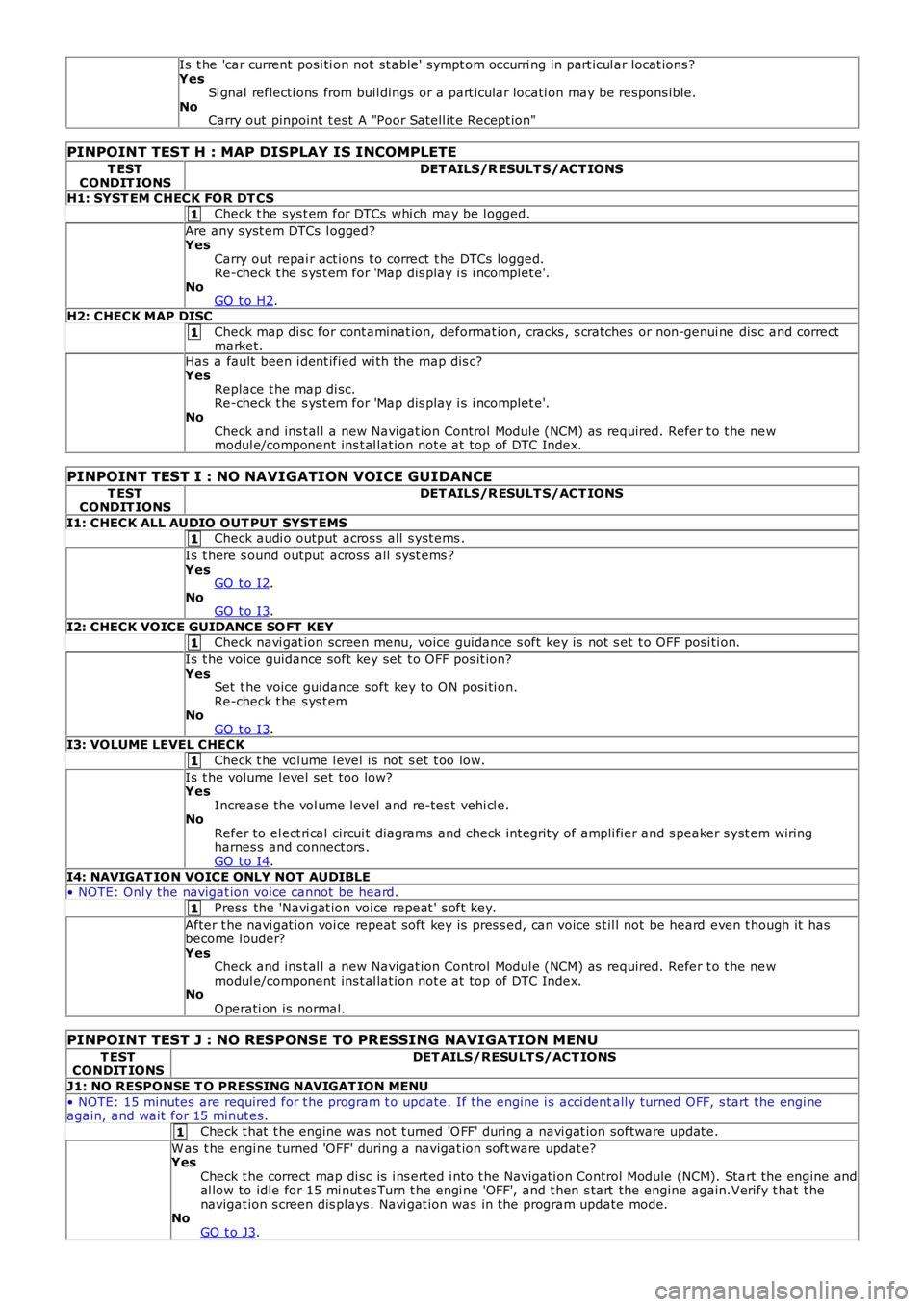
Is t he 'car current posi ti on not st able' sympt om occurri ng in part icul ar locat ions ?YesSi gnal reflecti ons from buil dings or a part icular locati on may be respons ible.NoCarry out pinpoint t est A "Poor Satell it e Recept ion"
PINPOINT TEST H : MAP DISPLAY IS INCOMPLETE
T ESTCONDIT IONSDET AILS/R ESULT S/ACT IONS
H1: SYST EM CHECK FOR DT CSCheck t he sys t em for DTCs whi ch may be l ogged.
Are any s yst em DTCs l ogged?YesCarry out repai r act ions t o correct t he DTCs logged.Re-check t he s ys t em for 'Map dis play i s i ncomplet e'.NoGO t o H2.H2: CHECK MAP DISC
Check map di sc for cont aminat ion, deformat ion, cracks , s cratches or non-genui ne dis c and correctmarket.Has a fault been i dent ified wi th the map dis c?YesReplace t he map di sc.Re-check t he s ys t em for 'Map dis play i s i ncomplet e'.NoCheck and ins t al l a new Navigat ion Control Modul e (NCM) as required. Refer t o t he newmodul e/component ins t al lat ion not e at top of DTC Index.
PINPOINT TEST I : NO NAVIGATION VOICE GUIDANCE
T ESTCONDIT IONSDET AILS/R ESULT S/ACT IONS
I1: CHECK ALL AUDIO OUT PUT SYST EMSCheck audi o output acros s all s yst ems .
Is t here s ound output across all s ys t ems ?YesGO t o I2.NoGO t o I3.
I2: CHECK VOICE GUIDANCE SO FT KEYCheck navi gat ion screen menu, voice guidance s oft key is not s et t o OFF posi ti on.
Is t he voice guidance soft key set t o OFF pos it ion?YesSet t he voice guidance soft key to O N posi ti on.Re-check t he s ys t emNoGO t o I3.I3: VOLUME LEVEL CHECK
Check t he vol ume l evel is not s et t oo low.
Is t he volume l evel s et too low?YesIncrease the vol ume level and re-tes t vehi cl e.NoRefer to el ect ri cal circui t diagrams and check int egrit y of ampli fier and s peaker s yst em wiringharnes s and connect ors .GO t o I4.
I4: NAVIGAT ION VOICE ONLY NOT AUDIBLE• NOTE: Onl y the navigat ion voice cannot be heard.
Press the 'Navi gat ion voi ce repeat ' s oft key.
After t he navi gat ion voi ce repeat soft key is pres s ed, can voice s t il l not be heard even t hough it hasbecome l ouder?YesCheck and ins t al l a new Navigat ion Control Modul e (NCM) as required. Refer t o t he newmodul e/component ins t al lat ion not e at top of DTC Index.NoO perati on is normal.
PINPOINT TEST J : NO RESPONSE TO PRESSING NAVIGATION MENU
T ESTCONDIT IONSDET AILS/RESULT S/ACT IONS
J1: NO RESPONSE T O PRESSING NAVIGAT ION MENU
• NOTE: 15 minutes are required for t he program t o update. If the engine i s acci dentally turned OFF, s tart the engi neagain, and wait for 15 minut es.
Check t hat t he engine was not t urned 'O FF' during a navi gat ion software updat e.
W as t he engi ne turned 'OFF' during a navigat ion s oft ware updat e?YesCheck t he correct map di sc is i ns erted i nto t he Navigati on Control Module (NCM). Start the engine andal low to idle for 15 mi nut es Turn t he engi ne 'OFF', and t hen s tart the engine again.Verify t hat t henavigat ion s creen dis plays . Navi gat ion was in the program update mode.NoGO t o J3.
Page 1866 of 3229
1
1
1
1
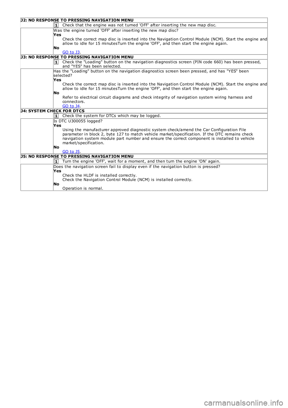
J2: NO RESPONSE T O PRESSING NAVIGAT ION MENU
Check t hat t he engine was not t urned 'O FF' aft er ins ert ing t he new map di s c.
W as t he engi ne turned 'OFF' after i nserti ng the new map dis c?YesCheck t he correct map di sc is i ns erted i nto t he Navigati on Control Module (NCM). Start the engine andal low to idle for 15 mi nut es Turn t he engi ne 'OFF', and t hen s tart the engine again.NoGO t o J3.
J3: NO RESPONSE T O PRESSING NAVIGAT ION MENU
Check t he "Loading" butt on on t he navi gat ion di agnos ti cs screen (PIN code 660) has been pres s ed,and "Y ES" has been sel ect ed.
Has the "Loadi ng" but ton on the navigati on diagnost ics s creen been pres s ed, and has "Y ES" beensel ect ed?YesCheck t he correct map di sc is i ns erted i nto t he Navigati on Control Module (NCM). Start the engine andal low to idle for 15 mi nut es Turn t he engi ne 'OFF', and t hen s tart the engine again.NoRefer to el ect ri cal circui t diagrams and check int egrit y of navi gat ion sys tem wi ring harnes s andconnect ors .GO t o J4.
J4: SYST EM CHECK FO R DT CSCheck t he s ys t em for DTCs which may be l ogged.
Is DTC U300055 l ogged?YesUsi ng t he manufact urer approved diagnost ic s ys tem check/amend t he Car Configurat ion Fi leparameter i n block 2, byt e 127 t o mat ch vehi cl e market /s peci fi cat ion. If the DTC remains checknavigat ion s ys tem modul e part number and ensure t he correct component is ins tall ed to vehi cl emarket/s pecificati on.NoGO t o J5.J5: NO RESPONSE T O PRESSING NAVIGAT ION MENU
Turn t he engi ne 'OFF', wai t for a moment , and then t urn the engine 'ON' agai n.
Does t he navigati on s creen fai l t o di spl ay even i f the navigat ion but ton i s pres s ed?YesCheck t he HLDF is ins tall ed correct ly.Check t he Navi gati on Cont rol Module (NCM) i s ins tal led correct ly.NoOperati on is normal.
Page 2062 of 3229
Publi s hed: 11-May-2011
Anti-Theft - Passive - Anti-Theft - Passive
Diagnosi s and Tes ti ng
Principles of Operation
For a detail ed descripti on of the Pas s ive Ant i-Theft Sys t em (PATS), refer t o t he relevant Des cript ion and Operat ion secti onin the workshop manual.REFER to: Ant i-Theft - Pas s ive (419-01B Anti -Theft - Pas s ive, Descripti on and Operat ion).
Inspection and Verification
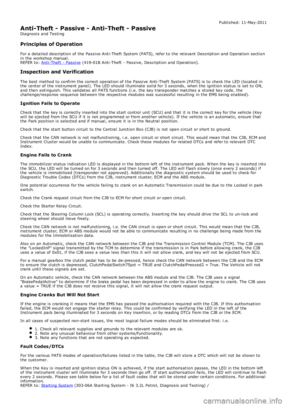
The best method t o confirm the correct operat ion of t he Pass i ve Ant i-Theft Syst em (PATS) is t o check t he LED (located i nt he cent er of t he ins t rument panel ). The LED s hould i ll uminate sol id for 3 s econds , when the i gnit ion s tat us is set t o ON,and t hen ext inguis h. Thi s validat es all PATS functi ons (i .e. the key t rans ponder matches a st ored key code, thechal lenge/res ponse sequence bet ween t he res pect ive modules was succes s ful res ult ing in t he EMS being enabled).
Ignition Fails to Operate
Check t hat the key i s correct ly i nserted i nto the s t art cont rol unit (SCU) and that i t is t he correct key for t he vehi cle (Keywil l be ejected from t he SCU i f it is not programmed or from anot her vehicl e). If the vehicle is an aut omati c, ens ure t hatt he Park pos it ion i s s el ect ed and if manual, ens ure it is in t he Neutral pos i ti on.
Check t hat the st art but ton circui t to the Cent ral Juncti on Box (CJB) i s not open circui t or s hort to ground.
Check t hat the CAN network is not mal functi oni ng, i .e. open circuit or s hort circui t. This woul d mean t hat the CJB, ECM andIns t rument Clus t er woul d be unabl e t o communicate. Check thes e modules for relat ed DTCs and refer t o relevant DTCIndex.
Engine Fails to Crank
The immobili zer s t atus i ndi cat ion LED i s dis played i n the bot tom left of the i nst rument pack. W hen the key i s i ns ert ed i nt ot he SCU, t he LED wi ll be t urned on for 3 s econds and t hen turned off. The LED will flas h s lowl y (once every 2 seconds ) i ft he vehi cl e is immobi lis ed (t ransponder not approved). Addit ionall y the di agnos ti c syst em s hould be us ed t o check forDiagnost ic Troubl e Codes (DTCs ) from the CJB, ins trument cl ust er, ECM and the ABS modul e.
One potent ial occurrence for the vehicl e fai ling to crank on an Automat ic Trans mi s sion coul d be due t o t he Locked in parks wit ch.
Check t he Crank reques t circui t from t he CJB t o ECM for short ci rcuit or open circuit .
Check t he St art er Rel ay Circuit .
Check t hat the St eeri ng Col umn Lock (SCL) is operat ing correctl y. Ins erti ng t he key should drive t he SCL t o un-l ock ands teeri ng wheel should move freel y.
Check t he CAN net work i s not malfunct ioning, i.e. the CAN ci rcuit i s open or short ci rcuit . Thi s would mean that t he CJB,ins t rument clus ter, ECM or ABS module would not be abl e t o communicate res ul ti ng in no chal lenge being made from t hemodules for the Immobil is ati on data.
Als o on an Aut omat ic, check the CAN network between t he CJB and the Transmis s ion Control Modul e (TCM). The CJB usest he "LockedInP" s ignal transmit ted by t he TCM to det ermi ne if t he t rans mis s ion i s in Park before all owing crank, the CJBus es a value of 0x01, i f the CJB s ees a value l ess than t his i t wil l not al low crank, and key wil l not be ejected from SCU.
For a manual gearbox t he clut ch pedal has to be de-pres s ed, hence check t he CAN network between t he CJB and t he ECMt o ensure t he cl utch i s depress ed, Clut chPedal Swit ch75pct = TRUE and Cl ut chPedalPress ed2 = True. The Vehicl e wil l notcrank unti l thes e s ignals are s et.
On an Aut omati c vehi cl e, check t he CAN network between t he ABS module and the CJB. The CJB uses a s ignal"BrakePedalActi ve" t o det ermi ne if t he brake pedal has been depres sed in order t o allow t he engine t o crank. The CJB us esa value = TRUE i f the CJB does not receive t hi s s ignal, i t wil l not al low t he crank reques t output.
Engine Cranks But Will Not Start
If the engine i s cranking i t means that t he EMS has pass ed t he authori s at ion required wit h t he CJB. If thi s authori s at ionfai led, the ECM would not engage the s t art er relay. Thi s coul d be confi rmed by verifyi ng t he LED in the l eft of t heIns t rument pack bei ng il lumi nat ed for 3 seconds on Key ins ert ion, or by reading DTCs from t he CJB or t he ECM.
In all cases of s us pected non-st art i s sues , the most l ogical fail ure modes s houl d be el imi nat ed first . i.e.
1. Check al l relevant suppli es and grounds to the relevant modul es are ok.2. Note any unus ual behavi our from other s yst ems /funct ionali ty.3. Note any funct ions t hat are not operati ng as expect ed.
Fault Codes/DTCs
For the vari ous PATS modes of operat ion/fail ures l is ted i n t he t abl e, t he CJB wi ll store a DTC whi ch wil l not be shown t ot he cus t omer.
W hen t he Key i s ins ert ed and ignit ion st atus ON is achieved, if t he s tart aut horis ation pas ses , the LED in t he bott om leftof the ins trument cl us t er will i ll uminate for 3 s econds t hen go off. If st art aut horis ati on fai ls , the LED wil l conti nue to fl as hevery 2 s econds . Pleas e s ee tabl e below for a li s t of fault codes that wil l be s tored under cert ain condi ti ons. For addi ti onalinformat ion.REFER to: St art ing Syst em (303-06A St art ing Sys tem - I6 3.2L Petrol, Di agnos is and Tes ti ng) /
Page 2313 of 3229
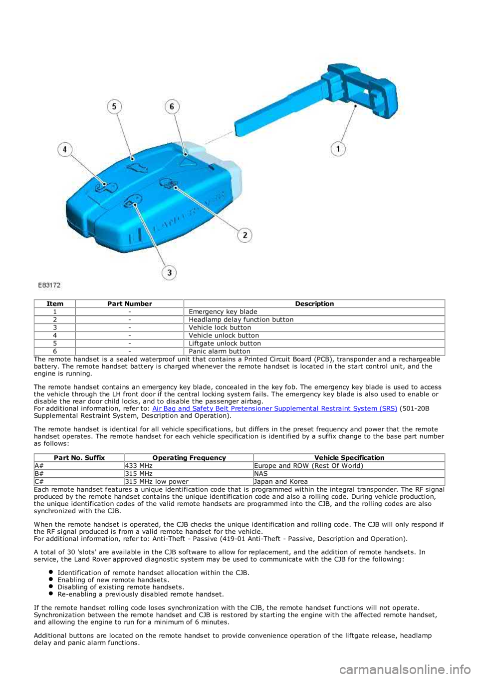
ItemPart NumberDescription1-Emergency key bl ade2-Headl amp delay funct ion but ton3-Vehicl e l ock button4-Vehicl e unlock button5-Li ftgate unlock butt on6-Panic alarm buttonThe remote hands et is a seal ed wat erproof uni t t hat contains a Printed Ci rcuit Board (PCB), transponder and a rechargeablebattery. The remote hands et batt ery i s charged whenever the remote hands et is located i n the s tart cont rol unit , and t heengi ne is running.
The remote hands et cont ai ns an emergency key blade, conceal ed in t he key fob. The emergency key bl ade i s us ed to acces sthe vehicle through the LH front door i f t he central locki ng syst em fai ls. The emergency key bl ade is als o us ed t o enable ordis able t he rear door chil d locks , and t o dis able t he pas senger ai rbag.For addit ional informat ion, refer t o: Ai r Bag and Safet y Belt Pretens ioner Supplement al Rest raint Sys tem (SRS) (501-20BSupplemental Res traint Sys tem, Des cription and Operat ion).
The remote hands et is identi cal for all vehicl e s peci ficat ions, but di ffers in t he pres et frequency and power that the remotehandset operates. The remot e handset for each vehicle specificat ion is ident ifi ed by a s uffix change to the base part numberas follows:
Part No. SuffixOperating FrequencyVehicle SpecificationA#433 MHzEurope and ROW (Rest Of W orld)B#315 MHzNASC#315 MHz low powerJapan and KoreaEach remot e handset features a uni que ident ifi cation code that is programmed within t he integral trans ponder. The RF si gnalproduced by t he remot e handset contains t he uni que ident ifi cation code and also a rolli ng code. Duri ng vehicl e product ion,the unique identification codes of the valid remot e handsets are programmed int o the CJB, and the roll ing codes are al sosynchronized wi th the CJB.
W hen the remote handset is operat ed, t he CJB checks t he unique i dent ificat ion and rol ling code. The CJB will only respond ifthe RF si gnal produced is from a val id remote hands et for the vehicle.For addit ional informat ion, refer t o: Anti -Theft - Pas si ve (419-01 Anti -Theft - Pas si ve, Des cript ion and Operati on).
A tot al of 30 'sl ots ' are availabl e in the CJB s oftware to al low for repl acement, and the addi tion of remote hands et s. Inservi ce, t he Land Rover approved di agnost ic system may be us ed to communicat e wit h the CJB for the followi ng:
Identi ficati on of remote handset all ocat ion wit hin t he CJB.Enabli ng of new remot e handsets .Disabl ing of exist ing remote handsets .Re-enabling a previ ously disabled remot e handset.
If the remote hands et rolling code l os es synchronizati on with t he CJB, t he remot e handset funct ions will not operate.Synchronizati on between the remote hands et and CJB is rest ored by s tart ing t he engine wit h t he affect ed remot e handset,and all owing the engine to run for a minimum of 6 mi nutes.
Addi tional buttons are located on the remote hands et to provide convenience operati on of t he li ftgat e rel ease, headlampdelay and panic al arm functions .
Page 2508 of 3229
• NOTE: The s ame reference point s mus t be chos en on bot h s ides when checking for changed dimens ions (e.g.bores , edges , beads /s wage l ines etc).
All of t he important external body dimens ions are li st ed in Tol erance Checks .For addit ional informat ion, refer t o: Body and Frame (501-26 Body Repai rs - Vehi cl e Speci fi c Informat ion andTolerance Checks , Descripti on and Operat ion).
Measurements wi th a meas uri ng/s trai ghtening jig.A meas uri ng/s traightening ji g is required for accurat e meas urement s of the body. The measuring s yst ems arecat egoris ed by t heir means of operati on:Mechanical meas uring s ys tem.Opti cal meas uri ng s ys t em.
Quick and accurate meas uri ng res ult s can be obtai ned usi ng comput eri sed meas uring s yst ems .
A minimum of t hree int act meas uri ng point s on t he body are requi red for meas urement s of length, wi dth and hei ghtdimens ions .
In s ome cases t his may mean making t he meas uri ng poi nts access ibl e. Al l of thes e meas uring sys tems can be used t omake body meas urements , provided al l t he equipment is avail able.
Planning a repair
The fol lowing decis i ons have t o be made before t he repai rs are s tarted:
Does the vehicl e need to be put on a s traightening ji g, or can it be st rai ght ened by other means ?Does the body need t o be meas ured?Do aggregates l ike engine or axles need t o be removed?• NOTE: It is preferable to repair body part s rat her t han t o renew them, as t his keeps the complet e body-s hel lint act .
W hi ch body parts need t o be renewed?W hi ch body parts can be repai red?
Obtaining spare parts
The avai labil it y of s pare part s oft en determines how eas il y t he body repairs can be carri ed out . The fol lowi ng procedure isrecommended:
Obtai n all t he data for the vehicl e, i ncl udi ng t ype, vehi cl e i dent ificati on number, trim code, engine i dent ificati onlet ters, i nit ial regis t rat ion et c.Es tabli sh all of the metal part s that need t o be renewed.Es tabli sh all of the at tached part s t hat need t o be renewed, including smal l parts li ke ri vet s, cl ips etc.
Straightening repairs
W ARNING: The us e of heat when pull ing t o s traighten body panels , (s uch as s ide members ), i s not recommended.Longi tudinal pulli ng, (hot or col d), is al s o not recommended. A smal l amount of s ide to si de pull is permis s ibl e, (col d).
W hen any t ype of pul li ng or st rai ght ening operat ion i s performed i t is i mport ant to obs erve for any movement i n adjacentpanel s.
A panel must retai n it s s t rength and integrit y, i f there is any doubt the panel mus t be renewed.
Straightening repairs are often required to res tore the body t o i ts origi nal s hape aft er an accident. This can be done wit h:
Ali gnment jigs .Univers al s trai ghtening and meas uri ng ji gs.W el di ng jig s ys tem.
The fol lowing poi nts mus t be foll owed to ens ure that t he repairs are carri ed out profes si onal ly and t hat all t he dimens ionsare correct aft er t he repai rs have been carri ed out.
Struct ure:- The repair s equence depends on the individual repair plan (t aki ng any neces sary dis as sembl y work intoaccount).- Clean t he at tachment areas .- Anchor t he vehi cl e free of s tres s on t he relevant s ys t em.- Support the aggregat es to take s train off the body.- Decide on at l eas t t hree meas uri ng/mounti ng poi nts that are undamaged and as far apart as pos s ible (forbasi c adjus tment ).- Check the di mens i ons of t he meas uri ng/mounti ng poi nts .Straightening:-• NOTE: Check di mensi ons and gaps conti nuous ly during s t raight eni ng.
A body i s always s traightened i n the oppos it e direct ion t o t hat of the i mpact . Always carry out st rai ght eningrepairs wi th the complet e body s hel l as s embled (do not cut out any part s beforehand). Carry out t hes traightening work i n s everal s t ages . This prevents the ris k of over st ret chi ng or of welded joi nts t eari ng out .Duri ng the individual st rai ght ening s t eps , rel ieve t ens i on by s triking wi th an aluminium hammer whi le the part iss ubject ed t o a t ensi le load (in t he area of pre-determined folding poi nt s , dent s , welded joi ns etc.).Speci al feat ures :- Ult ra high s t rength st eel cannot be st rai ght ened due to it s bri tt lenes s and mus t always be repl aced.
Cutting out body parts
Page 2528 of 3229
Publi s hed: 11-May-2011
Body Repairs - Vehicle Specific Information and Tolerance Checks - Body
and Frame
Des cript ion and Operat ion
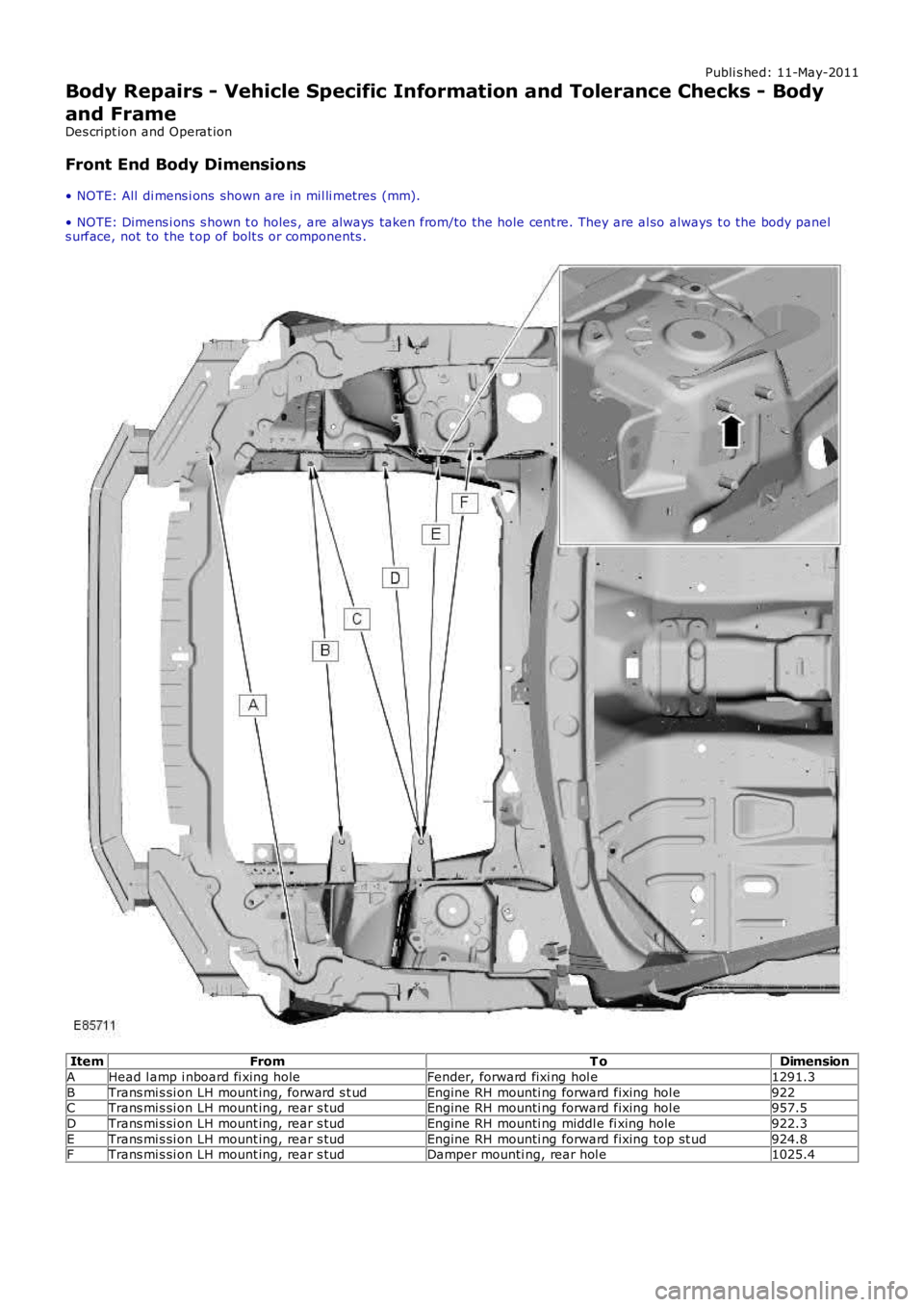
Front End Body Dimensions
• NOTE: All di mens i ons shown are in mil li metres (mm).
• NOTE: Dimens i ons s hown t o holes , are al ways taken from/to the hole cent re. They are al so always t o the body panels urface, not to the t op of bolt s or components .
ItemFromT oDimension
AHead l amp i nboard fi xing holeFender, forward fixi ng hol e1291.3
BTrans mi s si on LH mount ing, forward s t udEngine RH mounti ng forward fixing hol e922CTrans mi s si on LH mount ing, rear s tudEngine RH mounti ng forward fixing hol e957.5
DTrans mi s si on LH mount ing, rear s tudEngine RH mounti ng middl e fi xing hole922.3
ETrans mi s si on LH mount ing, rear s tudEngine RH mounti ng forward fixing top s t ud924.8FTrans mi s si on LH mount ing, rear s tudDamper mounti ng, rear hol e1025.4
Page 2550 of 3229
Publi s hed: 11-May-2011
Front End Sheet Metal Repairs - Front Side Member
Removal and Inst all ati on
• NOTE: The front s ide member i s s erviced as a s eparate weld on panel. This procedure is to fit a long s ect ion cut from thes ervice panel, dis carding t he rear part .
• NOTE: The s ervice panel is not ful ly wel ded.
• NOTE: The s ect ion must be made at leas t 20mm forward of the l aser wel d.
1. The front s i de member is replaced in conjuncti on wit h:
Front bumper cover
Front bumper
Hood lat ch panel
Both front fenders
Front bumper mount ing
Front s ide member clos ing panel
Fender apron panel front reinforcement
Fender apron l ower panel
• NOTE: It is al so neces sary t o remove t he engine and s us pens ion as an as s embly.
2. For addit ional informati on rel at ing to this repair procedurepleas e s ee t he foll owing:For addi ti onal informat ion, refer t o: Body and Frame (501-26Body Repai rs - Vehi cl e Speci fic Informat ion and ToleranceChecks , Descripti on and Operat ion) /Standard W orks hop Practi ces (100-00 General Informat ion,Des cript ion and Operat ion).
3. Remove the front s ide member clos ing panel.For addi ti onal informat ion, refer t o: Front Side Member Cl os i ngPanel (501-27 Front End Sheet Met al Repai rs , Removal andIns t allat ion).
4. Remove the radi ator cool ing pack.For addi ti onal informat ion, refer t o: Radiator (303-03A Engi neCooling - I6 3.2L Petrol, Removal and Ins tall ati on).
5. Remove the engine and front s uspens ion as an as s embly.
6. Rel eas e and lay as ide t he brake pipe.
7. LH Side: Release the bat tery juncti on box and posi ti on asi de.
8. LH Side: Remove the ai r int ake pi pe.
9. LH Side: Release and lay as ide t he brake pi pe at the si demember.
10. LH Side: Remove the ant i-Lock brake s ys tem (ABS) Module.For addi ti onal informat ion, refer t o: Anti -Lock Brake Syst em(ABS) Module (206-09A Ant i-Lock Control, Removal andIns t allat ion).
11. RH Side: Remove the winds hi eld was her res ervoir.For addi ti onal informat ion, refer t o: W i nds hiel d W as herRes ervoi r (501-16 W i pers and W as hers , Removal andIns t allat ion).
12. RH Side: Remove the engi ne mount ing bracket .For addi ti onal informat ion, refer t o: Engi ne Mount RH (303-01BEngine - TD4 2.2L Dies el, Removal and Ins tall ati on).
13. RH Side: Remove the fender apron brake pipes .
14. RH Side: Remove the fender apron A/C pipe.
15. Rel eas e and l ay as ide t he ins ulat ing mat eri al at t hebulkhead.
16. Rel eas e and l ay as ide t he wiring harnes s .
Page 2554 of 3229
Publi s hed: 11-May-2011
Front End Sheet Metal Repairs - Suspension Top Mount
Removal and Inst all ati on
Removal
• NOTE: The s uspens ion t op mount is s ervi ced as a s eparate wel d-on panel.
• NOTE: The s ervice panel is not ful ly wel ded.
• NOTE: The panel i s s erviced les s i ts wel d s t uds
1. The sus pens i on top mount i s repl aced i n conjunct ion wi th:
Front bumper cover
Front bumper armature
Hood
Hood lat ch panel
Both front fenders
Fender apron upper panel
Fender apron panel
Ins t rument panel
• NOTE: It is al so neces sary t o remove t he engine and s us pens ion as an as s embly.
2. For addit ional informati on rel at ing to this repair procedurepleas e s ee t he foll owing:For addi ti onal informat ion, refer t o: Body and Frame (501-26Body Repai rs - Vehi cl e Speci fic Informat ion and ToleranceChecks , Descripti on and Operat ion) /Standard W orks hop Practi ces (100-00 General Informat ion,Des cript ion and Operat ion).
3. Remove the fender apron panel.For addi ti onal informat ion, refer t o: Fender Apron Panel(501-27 Front End Sheet Met al Repairs , Removal andIns t allat ion).
4. Remove the i nst rument panel.For addi ti onal informat ion, refer t o: Ins t rument Panel - TD42.2L Di esel (501-12 Ins t rument Panel and Cons ole, Removaland Ins t allat ion).
5. Remove the rocker panel i nner t ri m panel.
6. Remove the B-pill ar lower trim panel .For addi ti onal informat ion, refer t o: B-Pi ll ar Lower Tri m Panel(501-05 Int eri or Trim and Ornament ati on, Removal andIns t allat ion).
7. Remove the engine and front s uspens ion as an as s embly.
8. RH Side: Remove t he pedal box.
9. RH Side: Remove t he brake mas ter cylinder.For addi ti onal informat ion, refer t o: Brake Mas t er Cyli nder(206-06 Hydraulic Brake Actuati on, Removal and Ins t al lat ion).
10. Rel eas e and l ay as ide t he carpet and ins ul ati ng mat erial att he inner bul khead.
11. Rel eas e and l ay as ide t he wiring harnes s .
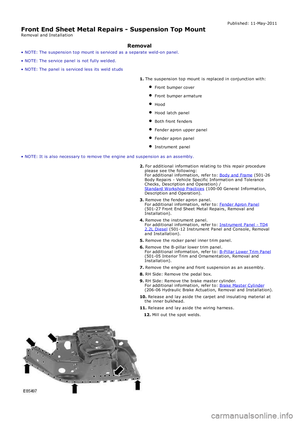
12. Mil l out t he s pot wel ds.