2006 LAND ROVER FRELANDER 2 check engine
[x] Cancel search: check enginePage 2557 of 3229
Publ is hed: 11-May-2011
Front End Sheet Metal Repairs - Front Side Member Section
Removal and Installation
Removal
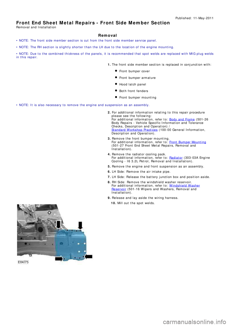
• NOTE: The front side member section is cut from the front side member service panel.
• NOTE: The RH section is slightly shorter than the LH due to the location of the engine mounting.
• NOTE: Due to the combined thickness of the panels, it is recommended that spot welds are replaced with MIG plug welds
in this repair.
1. The front s ide member s ect ion is replaced in conjunct ion wit h:
Front bumper cover
Front bumpe r a rma t ure
Hood lat ch panel
Both front fenders
Front bumpe r mount i ng
• NOTE: It is also necessary to remove the engine and suspension as an assembly.
2. Fo r a d d i t i o na l i nf o rma t i o n re l a t i ng t o t hi s re p a i r p ro ce d ure
please see the following:
Fo r a d d i t i o na l i nf o rma t i o n, re f e r t o : Body and Frame
(501-26
Body Repairs - Vehicle Specific Information and Tolerance
Checks, Description and Operation) /
St a nd a rd W o rks ho p P ra ct i ce s
(100-00 Ge ne ra l I nf o rma t i o n,
Description and Operation).
3. Re move t he f ront bumpe r mount i ng.
Fo r a d d i t i o na l i nf o rma t i o n, re f e r t o : Front Bumper Mount ing
(501-27 Front End Sheet Met al Re pai rs , Removal and
Installation).
4. Remove the radiator cooling pack.
Fo r a d d i t i o na l i nf o rma t i o n, re f e r t o : Radiator
(303-03A Engi ne
Cooling - I6 3.2L Petrol, Removal and Installation).
5. Remove the engine and front suspension as an assembly.
6. LH Side: Remove the air intake pipe.
7. LH Side: Release the battery junction box and position aside.
8. RH Side: Remove the windshield washer reservoir.
Fo r a d d i t i o na l i nf o rma t i o n, re f e r t o : Windshield Washer
Res ervoi r (501-16 W i pers and W as hers , Removal and
Installation).
9. Release and lay aside the wiring harness.
10. Mill out the spot welds.
Page 2560 of 3229

Publ is hed: 11-May-2011
Front End Sheet Metal Repairs - Fender Apron Panel
Removal and Installation
Removal
• NOTE: The fender apron panel is serviced as a separate weld-on panel. It is an assembly of the fender apron panel
reinforcement, fender apron lower panel and fender apron panel front extension.
• NOTE: The panel is serviced less its weld studs
1. The fender apron panel is replaced in conjunction with:
Front bumper cover
Hood lat ch panel
Both front fenders
Fender apron upper panel
2. Fo r a d d i t i o na l i nf o rma t i o n re l a t i ng t o t hi s re p a i r p ro ce d ure
please see the following:
Fo r a d d i t i o na l i nf o rma t i o n, re f e r t o : Body and Frame
(501-26
Body Repairs - Vehicle Specific Information and Tolerance
Checks, Description and Operation) /
St a nd a rd W o rks ho p P ra ct i ce s
(100-00 Ge ne ra l I nf o rma t i o n,
Description and Operation).
3. Remove the fender apron upper panel.
Fo r a d d i t i o na l i nf o rma t i o n, re f e r t o : Fender Apron Upper Panel
(501-27 Front End Sheet Met al Re pai rs , Removal and
Installation).
4. L H Si d e : Re mo ve t he a i r cl e a ne r.
Fo r a d d i t i o na l i nf o rma t i o n, re f e r t o : Air Cleaner
(303-12A
I nt a ke A i r Di s t ri b ut i o n a nd Fi l t e ri ng - I 6 3. 2L P e t ro l , Re mo va l
and Installation).
5. LH Side: Remove the air intake pipe.
6. LH Side: Remove the bat tery t ray.
Fo r a d d i t i o na l i nf o rma t i o n, re f e r t o : Battery Tray
(414-01
Battery, Mounting and Cables, Removal and Installation).
7. LH Side: Remove the engine lower support insulator.
Fo r a d d i t i o na l i nf o rma t i o n, re f e r t o : Engine Lower Support
Insulator (303-01A Engi ne - I6 3.2L Pet rol, Removal and
Installation).
8. LH Side: Release the battery junction box and position aside.
9. RH Side: Drain the cooling system.
Fo r a d d i t i o na l i nf o rma t i o n, re f e r t o : Cooling Sys tem Draining,
Filling and Bleeding (303-03A Engine Cooling - I6 3.2L Petrol,
General Procedures ).
10. RH Side: Evacuate the A/C system.
Fo r a d d i t i o na l i nf o rma t i o n, re f e r t o : Air Conditioning (A/C)
System Recovery, Evacuation and Charging (412-00 Cl i mat e
Co nt ro l Sys t e m - Ge ne ra l I nf o rma t i o n, Ge ne ra l P ro ce d ure s ).
11. RH Si d e : Re mo ve t he p o we r s t e e ri ng re s e rvo i r.
Fo r a d d i t i o na l i nf o rma t i o n, re f e r t o : P o we r St e e ri ng Fl ui d
Res ervoi r (211-02 Power St eeri ng, Removal and Ins t al lat i on).
12. RH Side: Release the coolant expansion tank and position
aside.
13. RH Side: Remove the engine mounting bracket.
Fo r a d d i t i o na l i nf o rma t i o n, re f e r t o : Engine Mount RH
(303-01A
Engine - I6 3.2L Petrol, Removal and Installation).
14. RH Side: Remove the windshield washer reservoir.
Fo r a d d i t i o na l i nf o rma t i o n, re f e r t o : Windshield Washer
Res ervoi r (501-16 W i pers and W as hers , Removal and
Installation).
15. RH Side: Remove the fender apron A/C pipes.
16. Remove the shock absorber and spring assembly.
Fo r a d d i t i o na l i nf o rma t i o n, re f e r t o : Sho ck A b s o rb e r a nd Sp ri ng
Assembly (204-01 Front Sus pens i on, Removal and
Installation).
17. Release and lay aside the wiring harness.
Page 2564 of 3229
Publ is hed: 11-May-2011
Front End Sheet Metal Repairs - Fender Apron Panel Reinforcement
Removal and Installation
Removal
• NOTE: The fender apron panel reinforcement has to be unpicked from the fender apron panel service panel, it is not
available separately.
• NOTE: The RH panel is serviced less its weld studs 1. T he f e nd e r a p ro n p a ne l re i nf o rce me nt i s re p l a ce d i n
conjunct ion wit h:
Front bumper cover
Hood lat ch panel
Both front fenders
Fender apron upper panel
2. Fo r a d d i t i o na l i nf o rma t i o n re l a t i ng t o t hi s re p a i r p ro ce d ure
please see the following:
Fo r a d d i t i o na l i nf o rma t i o n, re f e r t o : Body and Frame
(501-26
Body Repairs - Vehicle Specific Information and Tolerance
Checks, Description and Operation) /
St a nd a rd W o rks ho p P ra ct i ce s
(100-00 Ge ne ra l I nf o rma t i o n,
Description and Operation).
3. Remove the fender apron upper panel.
Fo r a d d i t i o na l i nf o rma t i o n, re f e r t o : Fender Apron Upper Panel
(501-27 Front End Sheet Met al Re pai rs , Removal and
Installation).
4. Remove the front shock absorber.
Fo r a d d i t i o na l i nf o rma t i o n, re f e r t o : Front Shock Abs orber
(204-01 Front Suspension, Removal and Installation).
5. LH Side: Remove the engine support insulator.
Fo r a d d i t i o na l i nf o rma t i o n, re f e r t o : Engine Upper Support
Insulator (303-01B Engi ne - TD4 2.2L Di es el, Removal and
Installation).
6. LH Side: Remove the bat tery t ray.
Fo r a d d i t i o na l i nf o rma t i o n, re f e r t o : Battery Tray
(414-01
Battery, Mounting and Cables, Removal and Installation).
7. LH Side: Remove the air intake pipe.
8. LH Side: Release the battery junction box and position aside.
9. RH Side: Remove the windshield washer reservoir.
Fo r a d d i t i o na l i nf o rma t i o n, re f e r t o : Windshield Washer
Res ervoi r (501-16 W i pers and W as hers , Removal and
Installation).
10. RH Side: Remove the engine mounting bracket.
Fo r a d d i t i o na l i nf o rma t i o n, re f e r t o : Engine Mount RH
(303-01B
Engine - TD4 2.2L Diesel, Removal and Installation).
11. RH Side: Release the coolant expansion tank and lay it
aside.
12. RH Side: Evacuate the A/C system.
Fo r a d d i t i o na l i nf o rma t i o n, re f e r t o : Air Conditioning (A/C)
System Recovery, Evacuation and Charging (412-00 Cl i mat e
Co nt ro l Sys t e m - Ge ne ra l I nf o rma t i o n, Ge ne ra l P ro ce d ure s ).
13. RH Side: Remove the fender apron A/C pipes.
14. RH Side: Release and lay aside the insulating material at the
bulkhead.
15. Release and lay aside the wiring harness.
Page 2574 of 3229
Publ is hed: 11-May-2011
Front End Sheet Metal Repairs - Front Side Member Closing Panel
Removal and Installation
Removal
• NOTE: The front side member closing panel must be unpicked from the front side member and suspension top mount
assembly, it is not serviced separately.
• NOTE: The panel is serviced less its weld studs
1. The front side member closing panel is replaced in conjunction
with:
Front bumper cover
Front bumper
Hood lat ch panel
Both front fenders
Front bumpe r mount i ng
Fender apron l ower panel
Fender apron panel front reinforcement
Front s i de me mbe r
• NOTE: It is also necessary to remove the engine and suspension as an assembly.
2. Fo r a d d i t i o na l i nf o rma t i o n re l a t i ng t o t hi s re p a i r p ro ce d ure
please see the following:
Fo r a d d i t i o na l i nf o rma t i o n, re f e r t o : Body and Frame
(501-26
Body Repairs - Vehicle Specific Information and Tolerance
Checks, Description and Operation) /
St a nd a rd W o rks ho p P ra ct i ce s
(100-00 Ge ne ra l I nf o rma t i o n,
Description and Operation).
3. Re move t he f ront s i de me mbe r.
Fo r a d d i t i o na l i nf o rma t i o n, re f e r t o : Front Side Member
(501-27
Front End Sheet Metal Repairs, Removal and Installation).
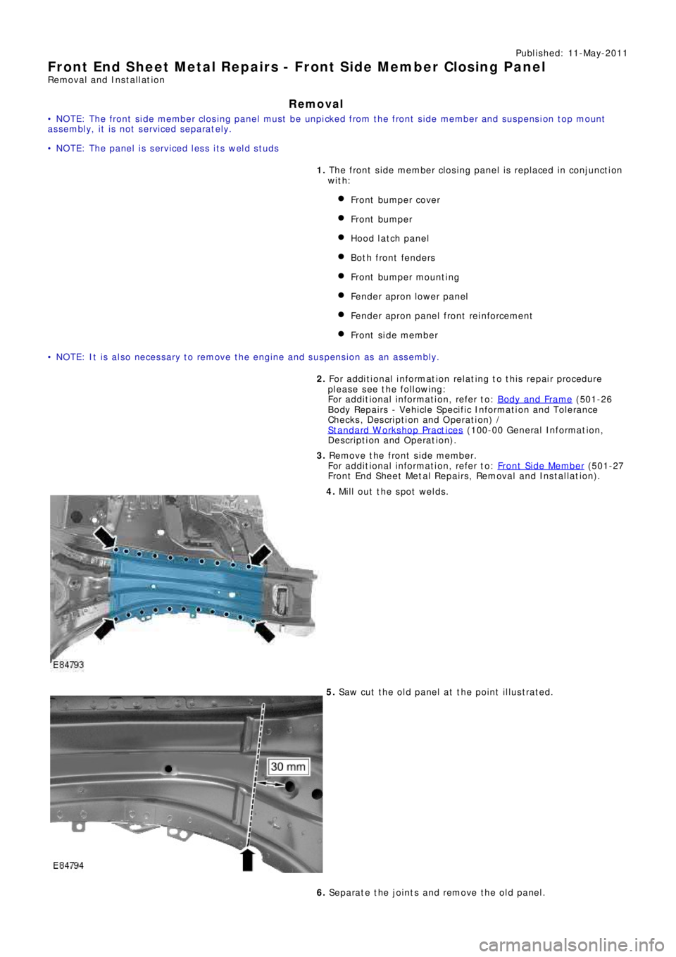
4. Mill out the spot welds.
5. Saw cut the old panel at the point illustrated.
6. Separate the joints and remove the old panel.
Page 2704 of 3229
18. WARNING: Make sure that a new steering column flexible coupling bolt is
installed.
Connect the steering column to the steering gear.
Torque: 25 Nm18.
Connect and s ecure t he cat alys t moni t or s ens or el ect ri cal connect ors . 19.
Install the 2 subframe mounting bolts and remove the jack. 20.
Install the engine undershield.
Refer to: Engine Undershield
(501-02 Front End Body Panel s, Removal and
Installation). 21.
Install the wheels and tires.
Refer to: W heel and Tire
(204-04 W heels and Tires , Removal and Ins t all at i on). 22.
Refill and bleed the power steering.
Refer to: Power Steering System Bleeding
(211-00 St eeri ng Sys t em - General
Informat ion, General Procedures). 23.
Using only four wheel alignment equipment approved by Land Rover, check and adjust
the wheel alignment. 24.
Page 2724 of 3229

Contents
4
L
Climate control
AIR VENTS ................................................... 101
MANUAL CLIMATE CONTROL ...................... 102
AUTOMATIC CLIMATE CONTROL ................. 103
HEATED WINDOWS AND MIRRORS ............ 104
AUXILIARY HEATER ..................................... 104
ELECTRIC SUNROOF .................................... 105
Convenience features
SUN VISORS ................................................ 107
CLOCK .......................................................... 107
CIGAR LIGHTER ........................................... 109
ASHTRAY ..................................................... 109
AUXILIARY POWER SOCKETS ..................... 110
CUP HOLDERS ............................................. 111
STORAGE COMPARTMENTS ........................ 112
Starting the engine
GENERAL INFORMATION ............................. 113
STARTING A PETROL ENGINE ..................... 114
STARTING A DIESEL ENGINE ....................... 115
DIESEL PARTICULATE FILTER (DPF) ........... 116
Transmission
MANUAL TRANSMISSION ............................ 118
AUTOMATIC TRANSMISSION ...................... 118
TECHNICAL SPECIFICATIONS ...................... 122
Brakes
PRINCIPLE OF OPERATION .......................... 123
HINTS ON DRIVING WITH ABS .................... 123
PARKING BRAKE .......................................... 124
Parking aid
PRINCIPLE OF OPERATION .......................... 126
USING THE PARKING AID ............................ 127
Driving hints
GENERAL DRIVING POINTS ......................... 128
REDUCED ENGINE PERFORMANCE ............. 128
RUNNING-IN ................................................ 128
ECONOMICAL DRIVING ................................ 129
Cruise control
PRINCIPLE OF OPERATION .......................... 130
USING CRUISE CONTROL ............................ 130
Terrain response
PRINCIPLE OF OPERATION .......................... 132
USING TERRAIN RESPONSE ........................ 132
Hill descent control (HDC)
PRINCIPLE OF OPERATION .......................... 136
USING HDC ................................................... 137
Traction control
USING TRACTION CONTROL ........................ 139
Stability control
PRINCIPLE OF OPERATION .......................... 140
USING STABILITY CONTROL ........................ 141
Fuel and refuelling
SAFETY PRECAUTIONS................................. 142
FUEL QUALITY .............................................. 142
RUNNING OUT OF FUEL................................ 144
FUEL CUT-OFF............................................... 144
FUEL FILLER FLAP ........................................ 144
REFUELLING ................................................. 145
TECHNICAL SPECIFICATIONS ....................... 146
Load carrying
GENERAL INFORMATION.............................. 147
LUGGAGE ANCHOR POINTS ......................... 148
LUGGAGE COVERS ....................................... 149
Towing
TOWING A TRAILER...................................... 150
LEVELLING.................................................... 151
ESSENTIAL TOWING CHECKS ...................... 151
RECOMMENDED TOWING WEIGHTS ............ 152
TOW BAR ...................................................... 153
Vehicle care
CLEANING THE ALLOY WHEELS................... 154
CLEANING THE EXTERIOR ............................ 154
CLEANING THE INTERIOR ............................ 155
REPAIRING MINOR PAINT DAMAGE ............ 156
Maintenance
GENERAL INFORMATION.............................. 157
OPENING AND CLOSING THE BONNET......... 160
ENGINE COMPARTMENT OVERVIEW ........... 161
ENGINE OIL CHECK....................................... 162
Page 2725 of 3229

Contents
5
R
ENGINE COOLANT CHECK ............................ 163
BRAKE AND CLUTCH FLUID CHECK ............. 165
POWER STEERING FLUID CHECK ................ 166
WASHER FLUID CHECK ................................ 167
TECHNICAL SPECIFICATIONS ...................... 169
Vehicle battery
BATTERY WARNING SYMBOLS ................... 171
BATTERY CARE ............................................ 171
USING BOOSTER CABLES ............................ 173
CHARGING THE VE HICLE BATTERY ............. 174
CHANGING THE VE HICLE BATTERY ............. 174
Wheels and tyres
GENERAL INFORMATION ............................. 176
TYRE CARE ................................................... 177
USING WINTER TYRES................................. 183
CHANGING A ROAD WHEEL ......................... 183
TYRE REPAIR KIT ......................................... 187
USING SNOW CHAINS.................................. 192
TYRE GLOSSARY.......................................... 193
TECHNICAL SPECIFICATIONS ...................... 194
Fuses
FUSE BOX LOCATIONS ................................. 195
CHANGING A FUSE ....................................... 195
FUSE SPECIFICATION CHART....................... 196
Emergency equipment
HAZARD WARNING FLASHERS .................... 204
WARNING TRIANGLE ................................... 204
Status after a collision
DRIVING AFTER A COLLISION...................... 205
INSPECTING SAFETY SYSTEM COMPONENTS ...
206
Vehicle recovery
TOWING POINTS .......................................... 207
LASHING POINTS ......................................... 208
TRANSPORTING THE VEHICLE..................... 208
TOWING THE VEHICLE ON FOUR WHEELS .. 208
Vehicle identification
VEHICLE IDENTIFICATION PLATE................. 210
VEHICLE IDENTIFI CATION NUMBER (VIN) ... 210
VEHICLE BUILD DATE PLATE ....................... 210
Technical specifications
ENGINE SPECIFICATIONS ............................ 211
WEIGHTS...................................................... 212
DIMENSIONS................................................ 213
Type approval
Declarations of conformity ........................... 215
Audio introduction
RADIO RECEPTION....................................... 218
Audio unit overview
AUDIO UNIT OVERVIEW............................... 219
Audio unit operation
ON OR OFF CONTROL .................................. 223
VOLUME CONTROL ...................................... 223
AUDIO CONTROL ......................................... 223
WAVEBAND BUTTON ................................... 224
AUTOSTORE CONTROL ................................ 225
STATION PRESET BUTTONS ........................ 226
TRAFFIC INFORMATION CONTROL .............. 226
Audio unit menus
RADIO DATA SYSTEM (RDS) ....................... 228
REGIONAL MODE (REG) .............................. 228
ENHANCED OTHER NETWORK (RDS-EON).. 229
ALTERNATIVE FREQUENCIES ...................... 229
NEWS BROADCASTS ................................... 230
PRIORITY PROGRAMME TYPE (PTY) .......... 231
RESETTING THE AUDIO UNIT ...................... 233
Digital audio broadcasting
GENERAL INFORMATION ............................. 234
AUDIO CONTROLS ....................................... 235
DISPLAY OPTIONS ....................................... 236
CHANNEL AUTOMATIC TUNING................... 236
CHANNEL OPTIONS ..................................... 236
PRESET BUTTONS ....................................... 238
SETTINGS..................................................... 240
Compact disc player
LOADING COMPACT DISCS ......................... 245
EJECTING COMPACT DISCS ........................ 246
EJECTING MULTIPLE CO MPACT DISCS....... 246
COMPACT DISC SELECTION ........................ 246
COMPACT DISC PLAYBACK ......................... 246
Page 2741 of 3229
21
Quick start
R
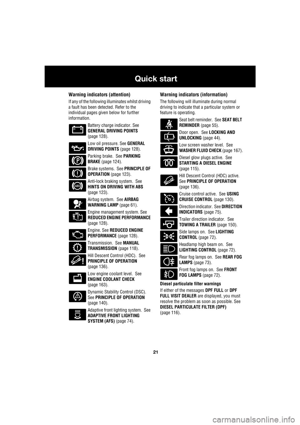
Warning indicators (attention)
If any of the following illuminates whilst driving
a fault has been detected. Refer to the
individual pages give n below for further
information.
Battery charge indicator. See
GENERAL DRIVING POINTS
(page 128).
Low oil pressure. See GENERAL
DRIVING POINTS (page 128).
Parking brake. See PARKING
BRAKE (page 124).
Brake systems. See PRINCIPLE OF
OPERATION (page 123).
Anti-lock braking system. See
HINTS ON DRIVING WITH ABS
(page 123).
Airbag system. See AIRBAG
WARNING LAMP (page 61).
Engine management system. See
REDUCED ENGINE PERFORMANCE
(page 128).
Engine. See REDUCED ENGINE
PERFORMANCE (page 128).
Transmission. See MANUAL
TRANSMISSION (page 118).
Hill Descent Control (HDC). See
PRINCIPLE OF OPERATION
(page 136).
Low engine coolant level. See
ENGINE COOLANT CHECK
(page 163).
Dynamic Stability Control (DSC).
See PRINCIPLE OF OPERATION
(page 140).
Adaptive front lighting system. See
ADAPTIVE FRONT LIGHTING
SYSTEM (AFS) (page 74).
Warning indicators (information)
The following will illuminate during normal
driving to indicate that a particular system or
feature is operating.
Seat belt reminder. See SEAT BELT
REMINDER (page 55).
Door open. See LOCKING AND
UNLOCKING (page 44).
Low screen washer level. See
WASHER FLUID CHECK (page 167).
Diesel glow plugs active. See
STARTING A DIESEL ENGINE
(page 115).
Hill Descent Control (HDC) active.
See PRINCIPLE OF OPERATION
(page 136).
Cruise control active. See USING
CRUISE CONTROL (page 130).
Direction indicator. See DIRECTION
INDICATORS (page 75).
Trailer direction indicator. See
TOWING A TRAILER (page 150).
Side lamps on. See LIGHTING
CONTROL (page 72).
Headlamp high beam on. See
LIGHTING CONTROL (page 72).
Rear fog lamps on. See REAR FOG
LAMPS (page 73).
Front fog lamps on. See FRONT
FOG LAMPS (page 72).
Diesel particulate filter warnings
If either of the messages DPF FULL or DPF
FULL VISIT DEALER are displayed, you must
resolve the problem as soon as possible. See
DIESEL PARTICULATE FILTER (DPF)
(page 116).