2006 LAND ROVER FRELANDER 2 diagram
[x] Cancel search: diagramPage 1122 of 3229
Publi s hed: 11-May-2011
Glow Plug System - Glow Plug System
Des cript ion and Operat ion
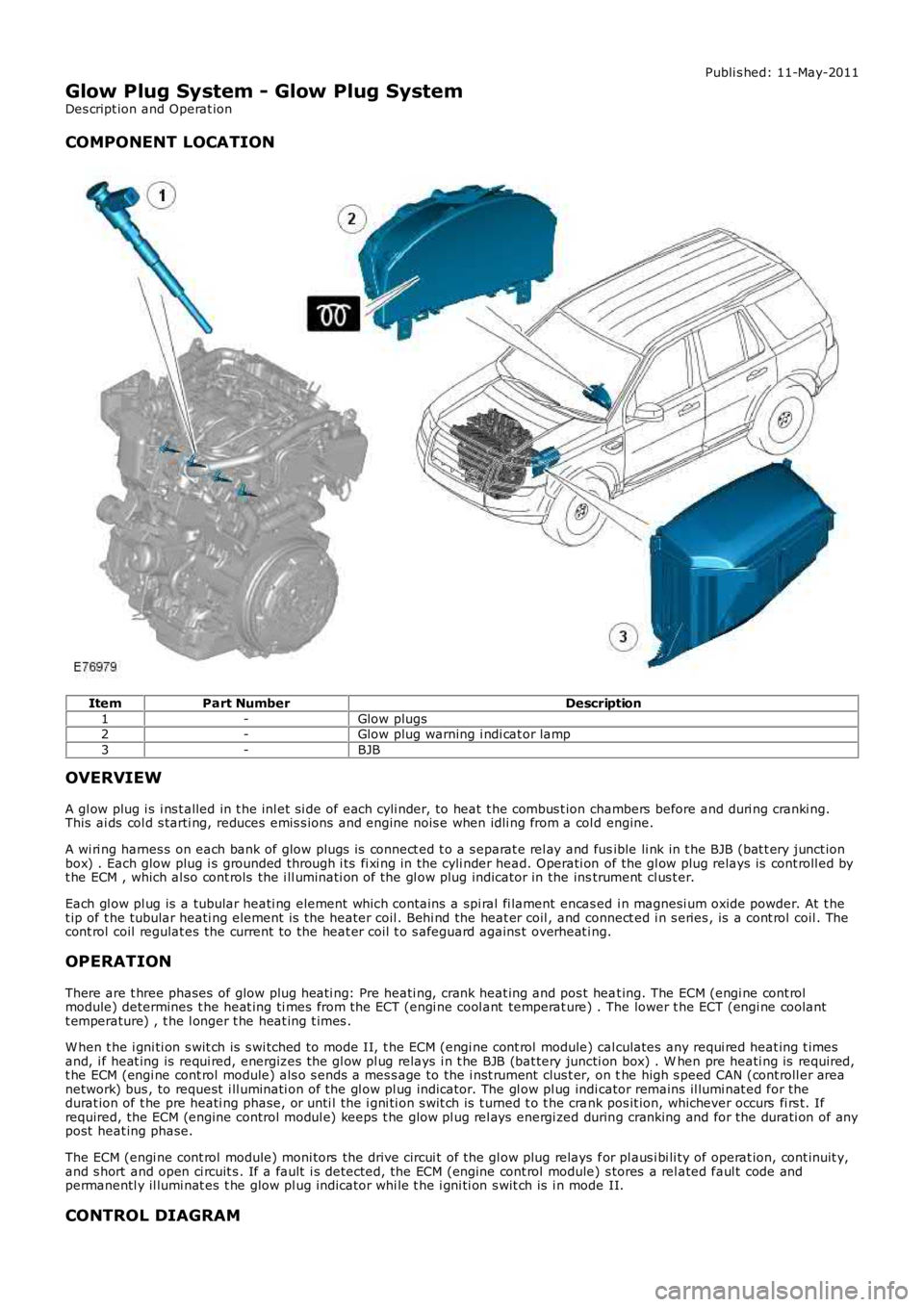
COMPONENT LOCATION
ItemPart NumberDescription
1-Glow plugs2-Glow plug warning i ndi cat or lamp
3-BJB
OVERVIEW
A gl ow plug i s i ns t alled in t he inl et si de of each cyli nder, to heat t he combus t ion chambers before and duri ng cranki ng.This ai ds col d s tarti ng, reduces emis s ions and engine nois e when idli ng from a col d engine.
A wi ri ng harnes s on each bank of glow plugs is connect ed t o a s eparat e rel ay and fusible li nk in t he BJB (bat t ery junct ionbox) . Each glow plug i s grounded through i ts fi xi ng in the cyli nder head. Operati on of the gl ow plug relays is cont roll ed byt he ECM , which al so cont rols the i ll uminati on of the gl ow plug indicator in the instrument cl us t er.
Each gl ow pl ug is a tubular heati ng element which cont ains a spi ral fi lament encas ed i n magnesi um oxide powder. At t het ip of t he tubular heati ng element is the heater coil . Behi nd the heat er coil , and connect ed i n s eries , is a cont rol coil . Thecont rol coil regulat es the current to the heat er coil t o s afeguard agains t overheat ing.
OPERATION
There are t hree phases of glow plug heati ng: Pre heati ng, crank heat ing and pos t heat ing. The ECM (engi ne cont rolmodule) determines t he heat ing ti mes from the ECT (engi ne cool ant temperat ure) . The lower t he ECT (engi ne coolantt emperature) , t he l onger t he heat ing t imes .
W hen t he i gni ti on s wit ch is s wi tched to mode II, t he ECM (engi ne cont rol module) calculates any requi red heat ing t imesand, i f heat ing is requi red, energizes the gl ow pl ug relays i n t he BJB (bat tery juncti on box) . W hen pre heati ng is required,t he ECM (engi ne cont rol module) als o s ends a mes s age to the i nst rument clus t er, on the high s peed CAN (cont roll er areanetwork) bus , to request i ll uminati on of the gl ow pl ug indicator. The gl ow pl ug indicator remains il lumi nat ed for thedurat ion of t he pre heati ng phase, or unti l the i gni ti on s wit ch is t urned t o t he crank pos it ion, whichever occurs fi rs t. Ifrequired, the ECM (engine control modul e) keeps t he glow pl ug rel ays energi zed during cranking and for the durati on of anypost heat ing phase.
The ECM (engi ne cont rol module) moni tors the drive circui t of the gl ow plug relays for pl aus i bi li ty of operat ion, cont inuit y,and s hort and open ci rcuit s . If a fault i s detected, the ECM (engine cont rol module) s tores a rel ated faul t code andpermanentl y il lumi nat es t he glow pl ug indicator whi le t he i gni ti on s wit ch is i n mode II.
CONTROL DIAGRAM
Page 1124 of 3229
Publi s hed: 11-May-2011
Glow Plug System - Glow Plug System
Diagnosi s and Tes ti ng
Principles of Operation
For a detail ed descripti on of the gl ow plug sys tem, refer t o t he rel evant Des cript ion and Operat ion s ecti on in the works hopmanual.REFER to: Gl ow Plug Sys tem (303-07B Glow Pl ug Syst em, Des cript ion and Operat ion).
Inspection and Verification
CAUTION: Di agnos is by s ubs ti tut ion from a donor vehicle is NO T acceptabl e. Subs ti tut ion of cont rol modules doesnot guarant ee confirmat ion of a faul t, and may als o caus e addit ional fault s i n t he vehi cl e being t est ed and/or t he donorvehi cl e.
1. Verify t he cus t omer concern.1.
2. Vis ually ins pect for obvious s igns of damage.2.
Visual InspectionElectrical
Fuse(s )Gl ow plug relayEngine management cont rol rel ayW iri ng harnes sElectrical connect or(s )Gl ow plug(s )Engine control modul e (ECM)
3. If an obvious cause for an obs erved or report ed concern is found, correct t he caus e (if pos s ible) beforeproceeding t o t he next s t ep3.
4. If t he caus e is not vis ually evi dent , verify t he sympt om and refer t o t he Sympt om Chart.4.
DTC Index
• NOTE: If the control modul e or a component i s s us pect and the vehicle remains under manufacturer warrant y, refer t o theW arranty Pol icy and Procedures manual (s ect ion B1.2), or determine i f any pri or approval programme is in operat ion, pri ort o the ins tall ati on of a new module/component.
• NOTE: Generic scan t ool s may not read the codes li st ed, or may read only fi ve digit codes . Mat ch the five di git s from t hes can tool to the firs t fi ve di git s of the seven digi t code l is ted to ident ify t he faul t (t he las t t wo digi ts gi ve addi ti onalinformat ion read by the manufact urer approved diagnos t ic s ys tem).
• NOTE: W hen performing volt age or res is t ance t est s , always use a digi tal mult imeter (DMM) accurat e t o t hree deci malplaces, and wi th an up-t o-date cal ibrat ion cert ificate. W hen tes ti ng res is t ance al ways take t he res is t ance of t he DMMleads i nt o account .
• NOTE: Check and recti fy bas ic faul ts before beginni ng diagnos t ic rout ines i nvol vi ng pinpoint t es t s.
• NOTE: Ins pect connect ors for s igns of water ingres s , and pins for damage and/or corros ion.
• NOTE: If DTCs are recorded and, aft er performi ng the pi npoi nt tes ts , a fault is not present , an int ermi tt ent concern maybe t he caus e. Always check for loose connect ions and corroded terminals .
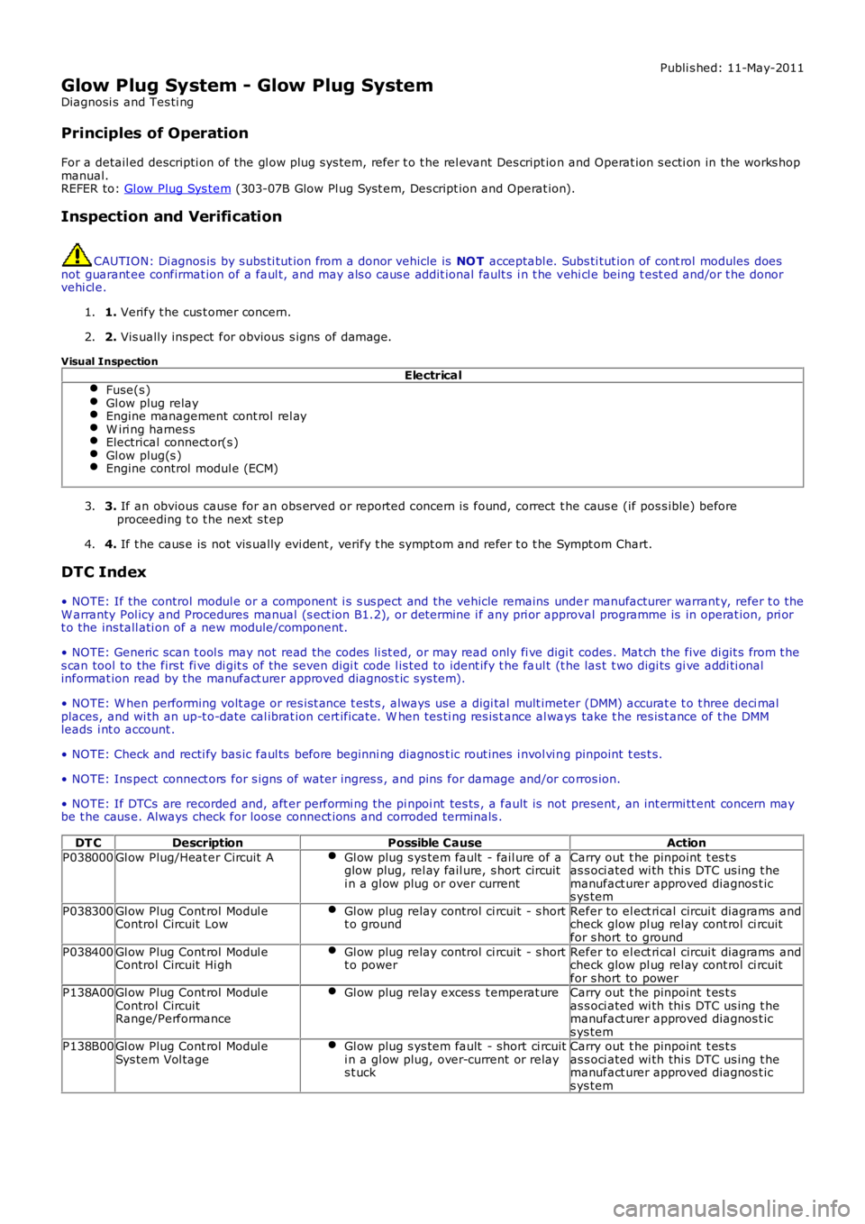
DT CDescriptionPossible CauseAction
P038000Gl ow Plug/Heat er Circuit AGl ow plug s ys tem fault - fail ure of aglow plug, rel ay fail ure, s hort circuiti n a gl ow plug or over current
Carry out t he pinpoint t es t sas s oci ated wi th thi s DTC us ing t hemanufact urer approved diagnos t ics ys tem
P038300Gl ow Plug Cont rol Modul eControl Circuit LowGl ow plug relay control ci rcuit - s hortt o groundRefer to el ect ri cal circui t diagrams andcheck glow pl ug rel ay cont rol ci rcuitfor s hort to ground
P038400Gl ow Plug Cont rol Modul eControl Circuit Hi ghGl ow plug relay control ci rcuit - s hortt o powerRefer to el ect ri cal circui t diagrams andcheck glow pl ug rel ay cont rol ci rcuitfor s hort to powerP138A00Gl ow Plug Cont rol Modul eControl CircuitRange/Performance
Gl ow plug relay exces s t emperat ureCarry out t he pinpoint t es t sas s oci ated wi th thi s DTC us ing t hemanufact urer approved diagnos t ics ys temP138B00Gl ow Plug Cont rol Modul eSys tem Vol tageGl ow plug s ys tem fault - short ci rcuiti n a gl ow plug, over-current or relays t uck
Carry out t he pinpoint t es t sas s oci ated wi th thi s DTC us ing t hemanufact urer approved diagnos t ics ys tem
Page 1137 of 3229
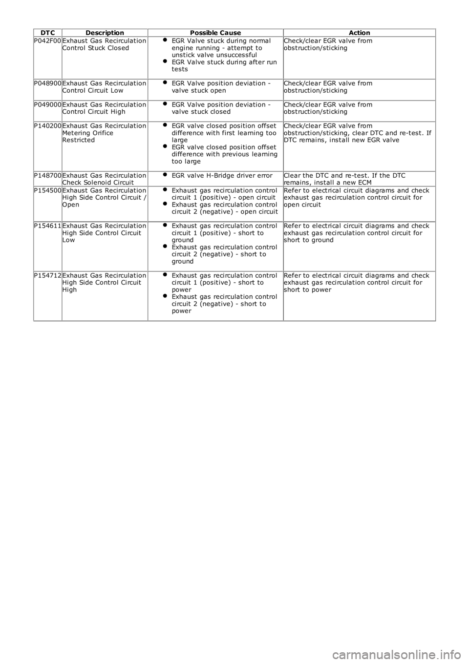
DT CDescriptionPossible CauseAction
P042F00Exhaus t Gas Recirculat ionControl St uck Clos edEGR Valve s tuck duri ng normalengi ne running - at tempt t ouns t ick valve unsucces s fulEGR Valve s tuck duri ng aft er runtes ts
Check/clear EGR valve fromobs t ructi on/s ti cking
P048900Exhaus t Gas Recirculat ionControl Ci rcuit LowEGR Valve pos it ion deviati on -val ve st uck openCheck/clear EGR valve fromobs t ructi on/s ti cking
P049000Exhaus t Gas Recirculat ionControl Ci rcuit Hi ghEGR Valve pos it ion deviati on -val ve st uck cl osedCheck/clear EGR valve fromobs t ructi on/s ti cking
P140200Exhaus t Gas Recirculat ionMet ering Ori ficeRes tricted
EGR val ve clos ed pos i ti on offsetdi fference wit h first learning toolargeEGR val ve clos ed pos i ti on offsetdi fference wit h previ ous learningtoo l arge
Check/clear EGR valve fromobs t ructi on/s ti cking, clear DTC and re-t es t . IfDTC remai ns , i ns t all new EGR valve
P148700Exhaus t Gas Recirculat ionCheck Sol enoi d Circui tEGR val ve H-Bridge driver errorCl ear the DTC and re-t es t. If the DTCremains , ins t al l a new ECM
P154500Exhaus t Gas Recirculat ionHi gh Side Control Ci rcuit /Open
Exhaust gas reci rculat ion controlci rcuit 1 (pos it ive) - open ci rcuitExhaust gas reci rculat ion controlci rcuit 2 (negat ive) - open circui t
Refer to el ect ri cal circui t diagrams and checkexhaust gas reci rculat ion control circui t foropen circui t
P154611Exhaus t Gas Recirculat ionHi gh Side Control Ci rcuitLow
Exhaust gas reci rculat ion controlci rcuit 1 (pos it ive) - short togroundExhaust gas reci rculat ion controlci rcuit 2 (negat ive) - s hort t oground
Refer to el ect ri cal circui t diagrams and checkexhaust gas reci rculat ion control circui t forshort to ground
P154712Exhaus t Gas Recirculat ionHi gh Side Control Ci rcuitHi gh
Exhaust gas reci rculat ion controlci rcuit 1 (pos it ive) - short topowerExhaust gas reci rculat ion controlci rcuit 2 (negat ive) - s hort t opower
Refer to el ect ri cal circui t diagrams and checkexhaust gas reci rculat ion control circui t forshort to power
Page 1198 of 3229
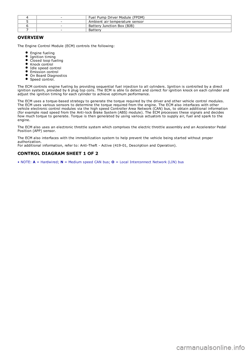
4-Fuel Pump Dri ver Module (FPDM)
5-Ambi ent ai r temperat ure sens or
6-Bat tery Juncti on Box (BJB)7-Bat tery
OVERVIEW
The Engi ne Control Module (ECM) controls t he fol lowing:
Engi ne fuel ingIgni ti on ti mingClos ed loop fuelingKnock controlIdl e s peed cont rolEmis s ion controlOn Board Diagnost icsSpeed cont rol.
The ECM controls engine fuel ing by provi ding s equent ial fuel inject ion t o al l cyli nders . Ignit ion i s cont rol led by a directignit ion sys tem, provi ded by 6 pl ug top coil s . The ECM is abl e t o detect and correct for i gni ti on knock on each cyl inder andadjus t the ignit ion t imi ng for each cyl inder to achieve opt imum performance.
The ECM us es a t orque-bas ed s trategy t o generate the t orque requi red by t he dri ver and ot her vehicle cont rol modules .The ECM us es various s ens ors t o determine t he t orque requi red from the engine. The ECM al so int erfaces wi th ot hervehi cl e elect ronic control modul es vi a t he high s peed Control ler Area Network (CAN) bus , to obt ain addit ional informat ion(for exampl e road speed from the Ant i-lock Brake Sys tem (ABS) module). The ECM proces ses t hese si gnal s and deci deshow much t orque t o generate. Torque i s t hen generat ed by us ing vari ous act uat ors to supply ai r, fuel and s park t o t heengi ne.
The ECM al so us es an el ect ronic throt tl e s yst em which compris es t he electric t hrot tle as sembl y and an Accel erator PedalPosi ti on (APP) s ensor.
The ECM al so interfaces wit h t he immobili zat ion sys tem t o help prevent t he vehi cl e being s t art ed wit hout properauthori zat ion.For addit ional informat ion, refer t o: Anti -Theft - Act ive (419-01, Des cri pt ion and Operati on).
CONTROL DIAGRAM SHEET 1 OF 2
• NOTE: A = Hardwi red; N = Medium s peed CAN bus; O = Local Int erconnect Network (LIN) bus
Page 1200 of 3229
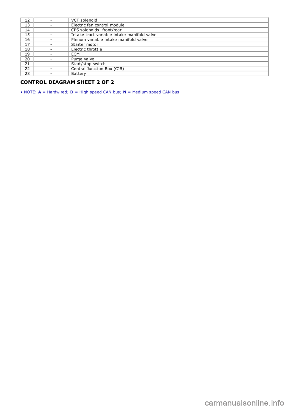
12-VCT s olenoid
13-El ect ri c fan control modul e
14-CPS s olenoids - front/rear15-Intake t ract variable int ake mani fol d valve
16-Pl enum variable int ake mani fol d val ve
17-St art er motor18-El ect ri c throt t le
19-ECM
20-Purge val ve21-St art /s t op swit ch
22-Central Juncti on Box (CJB)
23-Bat tery
CONTROL DIAGRAM SHEET 2 OF 2
• NOTE: A = Hardwi red; D = Hi gh s peed CAN bus ; N = Medi um s peed CAN bus
Page 1241 of 3229
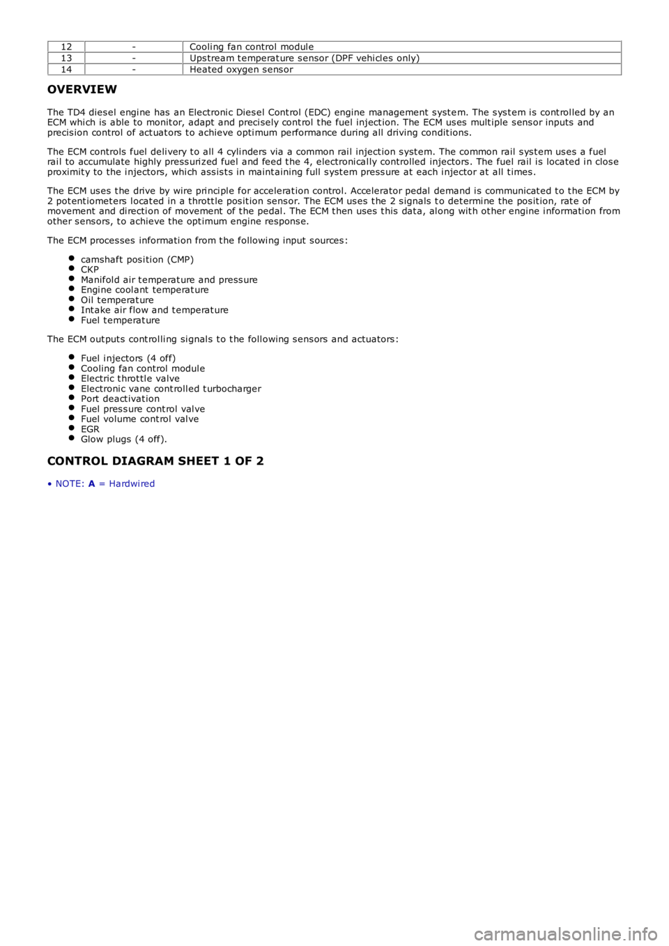
12-Cooli ng fan control modul e
13-Ups tream t emperat ure s ensor (DPF vehi cl es only)
14-Heated oxygen s ens or
OVERVIEW
The TD4 dies el engi ne has an Electroni c Dies el Cont rol (EDC) engine management s yst em. The s ys t em i s cont rol led by anECM whi ch is able to monit or, adapt and preci sel y cont rol t he fuel inject ion. The ECM us es mult iple s ens or inputs andprecis ion control of act uat ors t o achieve opti mum performance during all driving condit ions.
The ECM controls fuel deli very t o all 4 cyli nders via a common rai l inject ion s yst em. The common rail s ys t em us es a fuelrai l to accumulate highly press uri zed fuel and feed t he 4, electroni cal ly controlled injectors . The fuel rail i s located i n clos eproximit y to the i njectors, whi ch ass is t s in maint aining full s yst em press ure at each i njector at all t imes .
The ECM us es t he drive by wire pri nci pl e for accelerat ion control. Accelerator pedal demand i s communicat ed t o t he ECM by2 pot ent iomet ers l ocat ed in a thrott le pos it ion sens or. The ECM us es t he 2 s ignals to det ermi ne the pos it ion, rat e ofmovement and di recti on of movement of t he pedal . The ECM t hen uses t his dat a, al ong wit h ot her engine i nformati on fromother s ens ors, t o achieve the opt imum engine respons e.
The ECM proces ses informati on from t he followi ng input s ources :
camshaft pos i ti on (CMP)CKPManifol d air t emperat ure and press ureEngi ne cool ant temperat ureOil t emperat ureInt ake air flow and t emperat ureFuel t emperat ure
The ECM out put s cont rol li ng si gnal s t o t he foll owing s ens ors and actuators :
Fuel i njectors (4 off)Cooling fan control modul eElectric t hrot tl e valveElectroni c vane cont roll ed t urbochargerPort deact ivat ionFuel pres s ure cont rol val veFuel volume cont rol val veEGRGlow plugs (4 off).
CONTROL DIAGRAM SHEET 1 OF 2
• NOTE: A = Hardwi red
Page 1243 of 3229
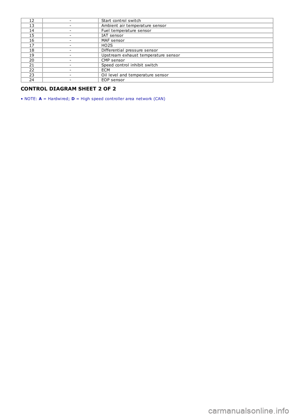
12-Start cont rol s wit ch
13-Ambient air t emperat ure s ensor
14-Fuel t emperature s ensor15-IAT sens or
16-MAF s ensor
17-HO2S18-Different ial pres s ure s ens or
19-Upst ream exhaus t temperature s ens or
20-CMP s ensor21-Speed control inhibit swi tch
22-ECM
23-Oil l evel and t emperature s ens or24-EOP s ensor
CONTROL DIAGRAM SHEET 2 OF 2
• NOTE: A = Hardwi red; D = Hi gh s peed controller area net work (CAN)
Page 1247 of 3229
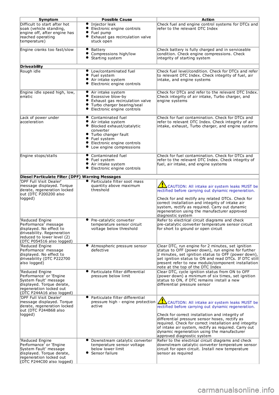
SymptomPossible CauseAction
Di fficul t t o s tart aft er hots oak (vehicle st andi ng,engine off, aft er engi ne hasreached operati ngt emperature)
Injector leakElectronic engine controlsFuel pumpExhaus t gas recircul ati on val ves tuck open
Check fuel and engine control sys tems for DTCs andrefer t o t he rel evant DTC Index
Engine cranks t oo fas t/s lowBatt eryCompres s ions high/lowSt arti ng s yst em
Check batt ery is fully charged and in s ervi ceablecondit ion. Check engine compres s ions . Checkint egrit y of s tart ing sys tem
Driveability
Rough idl eLow/contami nat ed fuelFuel s ys temAir i ntake s yst emElectronic engine controls
Check fuel l evel /condi ti on. Check for DTCs and referto relevant DTC Index. Check i ntegri ty of fuel, airint ake, and engi ne s yst ems
Engine i dl e s peed high, low,errati cAir i ntake s yst emExces s ive blow-byExhaus t gas recircul ati on val veTurbo charger bearing/sealElectronic engine controls
Check for DTCs and refer t o t he rel evant DTC Index.Check i nt egri ty of ai r intake, Turbo charger, andengi ne s ys t ems
Lack of power underaccel erati onContami nat ed fuelAir i ntake s yst emBlocked exhaus t/cat alyt icconverterTurbo changer faul tFuel s ys temElectronic engine controlsLow engine compres s ions
Check for fuel cont aminati on. Check for DTCs andrefer t o relevant DTC Index. Check int egrit y of airint ake, exhaus t, Turbo charger, and engi ne s ys t ems
Engine s t ops /st all sContami nat ed fuelFuel s ys temAir i ntake s yst emElectronic engine controls
Check for fuel cont aminati on. Check for DTCs andrefer t o t he rel evant DTC Index. Check int egrit y offuel, ai r intake, and engi ne s ys t ems
Diesel Particulate Filter (DPF) Warning Messages
'DPF Ful l Vi s it Dealer'mes s age dis played. Torquederat e, regenerati on lockedout (DTC P200200 als ol ogged)
Part iculat e fi lt er soot mas squant it y above maximumt hres hol dCAUTION: All i nt ake air s yst em leaks MUST berecti fi ed before carrying out dynamic regenerat ion.
Check for and recti fy any related DTCs . Check forcorrect ins tal lati on and int egrit y of i nt ake airsys t em, recti fy as requi red. Carry out dynami cregenerati on usi ng t he manufacturer approveddiagnos t ic s yst em
'Reduced Engi nePerformance' mes s agedis played. No effect t odri veabi lit y. Regenerat ionreduced t o lower level (2)(DTC P054516 al so logged)
Pre-cat alyt ic convertert emperature s ens or circui tvolt age bel ow t hres hol d
Refer to elect rical circui t diagrams and checkpre-cat al yti c convert er temperat ure s ens or ci rcuitfor s hort t o ground or open ci rcuit
'Reduced Engi nePerformance' mes s agedis played. No effect t odri veabi lit y (DTC P222700als o l ogged)
At mospheri c pres s ure s ens ordefecti veClear DTC, run engine for 2 mi nut es, s et igni ti onst atus to O FF (power down), run engine for further2 mi nut es , set i gni ti on s tat us to OFF (power down),set i gni ti on s tat us to ON and read DTCs. If DTC s t illpres ent refer t o new module/component ins tal lati onnot e at t he t op of the DTC Index
'Reduced Engi nePerformance' or 'EngineSyst em Fault ' mes sagedis played. Torque derate,regenerat ion l ocked out(DTC P244A16 al so logged)
Part iculat e fi lt er different ialpres s ure bel ow li mitClear DTC, cycle i gni ti on s tat us from ON t o OFF(power down) a mi ni mum of s i x ti mes , set i gni ti onst atus to O N, if DTC remains i ns t all a newdifferent ial pres sure s ens or
'DPF Ful l Vi s it Dealer'mes s age dis played. Torquederat e, regenerati on lockedout (DTC P244B68 als ol ogged)
Part iculat e fi lt er different ialpres s ure hi gh - engi ne prot ect ionacti veCAUTION: All i nt ake air s yst em leaks MUST berecti fi ed before carrying out dynamic regenerat ion.
Check for correct ins tall ati on and int egrit y ofdifferent ial pres sure s ens or hoses , rect ify asrequired. Check for correct i ns t allat ion and i ntegri tyof intake ai r sys tem, rect ify as requi red. Carry outdynami c regenerati on us ing t he manufacturerapproved di agnos ti c s ys t em'Reduced Engi nePerformance' or 'EngineSyst em Fault ' mes sagedis played. Torque derate,regenerat ion l ocked out(DTC P244C00 al so logged)
Downs tream catalyt ic convertert emperature s ens or volt agebelow lower li mitSensor failure
Refer to the el ect ri cal circui t diagrams and checkdowns t ream cat al yti c convert er temperat ure sens orci rcuit for open ci rcuit . Ins tal l new temperat uresens or as required