2006 LAND ROVER FRELANDER 2 diagram
[x] Cancel search: diagramPage 115 of 3229
Publ is hed: 28-Apr-2011
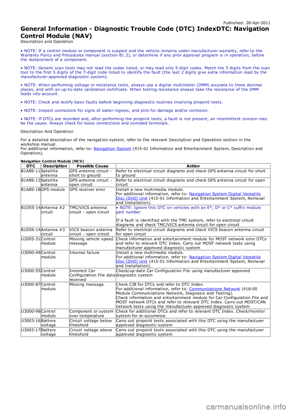
General Information - Diagnostic Trouble Code (DTC) IndexDTC: Navigation
Control Module (NAV)
Des cript ion and Operat ion
• NOTE: If a cont rol module or component i s s uspect and the vehicl e remai ns under manufacturer warrant y, refer t o t heW arranty Pol icy and Procedures manual (s ect ion B1.2), or determine i f any pri or approval program is i n operat ion, beforet he replacement of a component.
• NOTE: Generic scan t ool s may not read the codes li st ed, or may read only 5-digi t codes . Match t he 5 digi ts from t he s cant ool t o t he fi rs t 5 di gi ts of the 7-digit code li s ted t o i dent ify the fault (the last 2 digi ts gi ve ext ra informati on read by themanufacturer-approved di agnos ti c s ys t em).
• NOTE: W hen performing volt age or res is t ance t est s , always use a digi tal mult imeter (DMM) accurat e t o t hree deci malplaces, and wi th an up-t o-date cal ibrat ion cert ificate. W hen tes ti ng res is t ance al ways take t he res is t ance of t he DMMleads i nt o account .
• NOTE: Check and recti fy bas ic faul ts before beginni ng diagnos t ic rout ines i nvol vi ng pinpoint t es t s.
• NOTE: Ins pect connect ors for s igns of water ingres s , and pins for damage and/or corros ion.
• NOTE: If DTCs are recorded and, aft er performi ng the pi npoi nt tes ts , a fault is not present , an int ermi tt ent concern maybe t he caus e. Always check for loose connect ions and corroded terminals .
Des cript ion And Operat ion
For a detail ed descripti on of the navigat ion s yst em, refer to the relevant Des cri ption and Operati on s ect ion i n t heworks hop manual .For addit ional informat ion, refer t o: Navi gati on Sys t em (415-01 Informat ion and Ent ert ainment Sys t em, Descripti on andOperat ion).
Navigation C ontrol Module (NC V)
DT CDescriptionPossible CauseAction
B1A89-11Satell it eantennaGPS antenna circui t -s hort t o groundRefer t o electrical ci rcuit diagrams and check GPS ant enna ci rcuit for s hortt o ground
B1A89-13Satell it eantennaGPS antenna circui t -open ci rcuitRefer t o electrical ci rcuit diagrams and check GPS ant enna ci rcuit for opencircuit
B1A89-1BGPS moduleGPS receiver errorIns t all a new mult imedia modul e.For addit ional informat ion, refer t o: Navi gati on Sys t em Di gi tal Vers at ileDis c (DVD) Unit (415-01 Informat ion and Ent ert ainment Sys t em, Removaland Ins t allat ion).
B1D55-14Antenna #2circuitTMC/VICS antennacircuit - open ci rcuit• NOTE: Ignore t hi s DTC on vehicles wit h an E*, D* or C* s uffix modul epart number
If a fault is i dent ified wi th the TMC sys t em, refer t o elect rical circuitdiagrams and check TMC/VICS antenna circui t for open circuit
B1D56-14Antenna #3circuitVICS beacon antennacircuit - open ci rcuitRefer t o electrical ci rcuit diagrams and check VICS beacon ant enna circui tfor open circui t
U2005-31ControlmoduleMis s ing vehicle s peedmes s ageCheck i nformati on and ent ert ainment module for MOST network error DTCsand refer to relevant DTC Index. Carry out MOST net work tes ts usi ngmanufacturer approved diagnos ti c sys t emU3000-49ControlmoduleInt ernal fai lureIns t all a new mult imedia modul e.For addit ional informat ion, refer t o: Navi gati on Sys t em Di gi tal Vers at ileDis c (DVD) Unit (415-01 Informat ion and Ent ert ainment Sys t em, Removaland Ins t allat ion).
U3000-55ControlmoduleIncorrect CarConfigurat ion Fi le dat areceived
Check/up-dat e Car Confi gurati on File usi ng manufacturer approveddiagnost ic s ys tem
U3000-87ControlmoduleMis s ing mess ageCheck CJB for DTCs and refer t o DTC Index.For addit ional informat ion, refer t o: Communicati ons Net work (418-00Module Communi cat ions Network, Diagnos i s and Tes t ing).Check i nformati on and ent ert ainment module for Car Configurat ion Fil e andMOST net work DTCs and refer to rel evant DTC Index. Carry out MOST/CANnetwork tes t s usi ng t he manufacturer approved diagnost ic sys temU3000-98ControlmoduleComponent or s yst emover t emperat ureCheck for addi ti onal DTCs and refer to relevant DTC Index. Check/moni tors ys t em for re-occurrence
U3003-16Batt eryvolt ageCircui t vol tage belowt hreshol dCarry out pinpoi nt tes t s ass ociated wit h t hi s DTC us ing the manufact urerapproved diagnos t ic s yst em
U3003-17Batt eryvolt ageCircui t vol tage abovet hreshol dCarry out pinpoi nt tes t s ass ociated wit h t hi s DTC us ing the manufact urerapproved diagnos t ic s yst em
Page 116 of 3229
Publ is hed: 21-Oct -2011
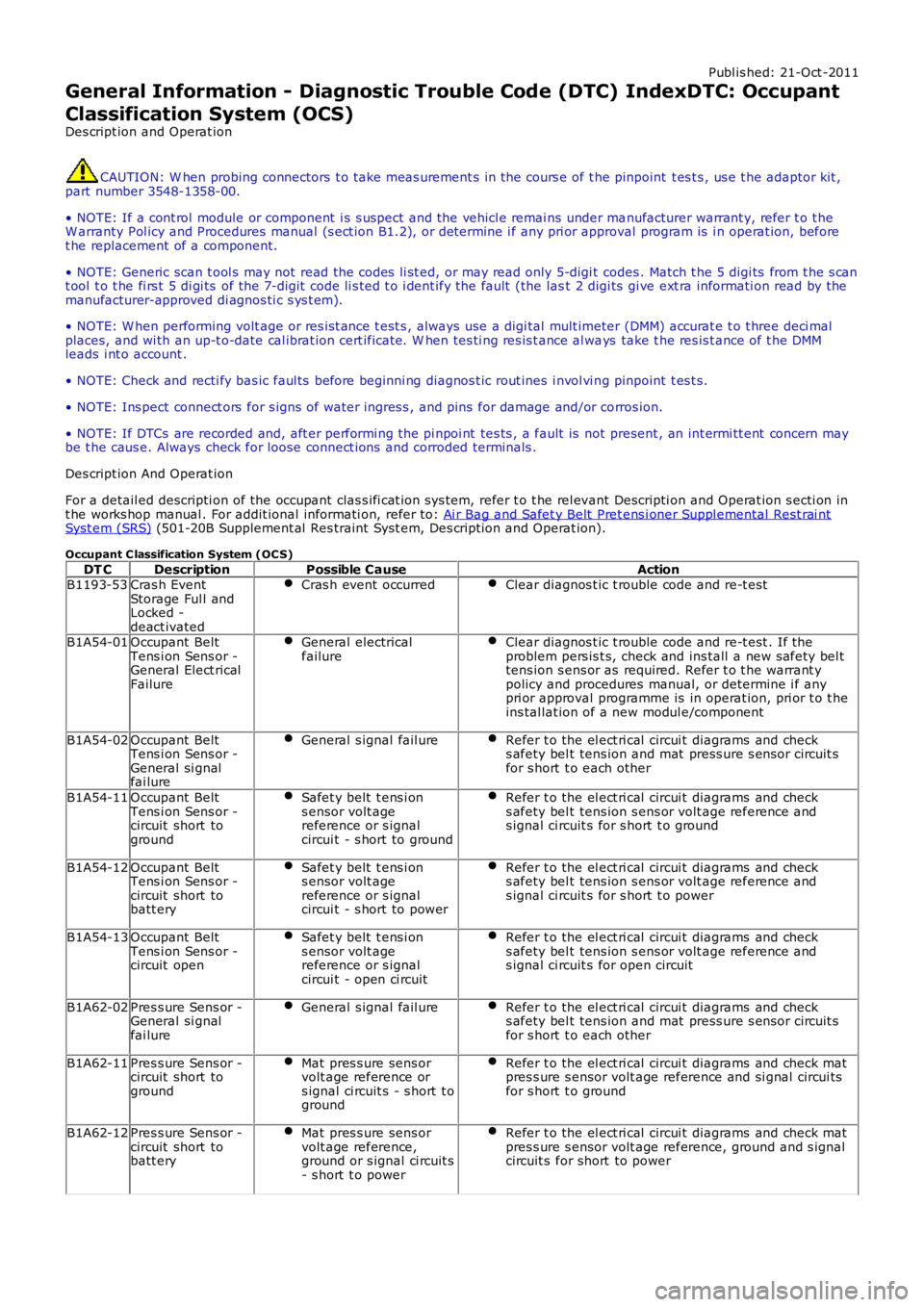
General Information - Diagnostic Trouble Code (DTC) IndexDTC: Occupant
Classification System (OCS)
Des cript ion and Operat ion
CAUTION: W hen probing connectors t o take meas urement s in the cours e of t he pinpoint t es t s , us e t he adaptor kit ,part number 3548-1358-00.
• NOTE: If a cont rol module or component i s s uspect and the vehicl e remai ns under manufacturer warrant y, refer t o t heW arranty Pol icy and Procedures manual (s ect ion B1.2), or determine i f any pri or approval program is i n operat ion, beforet he replacement of a component.
• NOTE: Generic scan t ool s may not read the codes li st ed, or may read only 5-digi t codes . Match t he 5 digi ts from t he s cant ool t o t he fi rs t 5 di gi ts of the 7-digit code li s ted t o i dent ify the fault (the last 2 digi ts gi ve ext ra informati on read by themanufacturer-approved di agnos ti c s ys t em).
• NOTE: W hen performing volt age or res is t ance t est s , always use a digi tal mult imeter (DMM) accurat e t o t hree deci malplaces, and wi th an up-t o-date cal ibrat ion cert ificate. W hen tes ti ng res is t ance al ways take t he res is t ance of t he DMMleads i nt o account .
• NOTE: Check and recti fy bas ic faul ts before beginni ng diagnos t ic rout ines i nvol vi ng pinpoint t es t s.
• NOTE: Ins pect connect ors for s igns of water ingres s , and pins for damage and/or corros ion.
• NOTE: If DTCs are recorded and, aft er performi ng the pi npoi nt tes ts , a fault is not present , an int ermi tt ent concern maybe t he caus e. Always check for loose connect ions and corroded terminals .
Des cript ion And Operat ion
For a detail ed descripti on of the occupant clas s ifi cat ion sys tem, refer t o t he rel evant Descripti on and Operat ion s ecti on int he works hop manual . For addit ional informati on, refer t o: Ai r Bag and Safet y Belt Pret ens i oner Suppl emental Rest rai ntSyst em (SRS) (501-20B Supplement al Res traint Syst em, Des cript ion and Operat ion).
Occupant C lassification System (OC S)
DT CDescriptionPossible CauseActionB1193-53Cras h EventStorage Ful l andLocked -deact ivated
Cras h event occurredClear diagnos t ic t rouble code and re-t est
B1A54-01Occupant BeltTens i on Sens or -General Elect ricalFailure
General electricalfailureClear diagnos t ic t rouble code and re-t est . If theproblem pers is t s, check and ins tall a new s afety bel ttens ion s ens or as required. Refer t o t he warrant ypolicy and procedures manual, or determine i f anypri or approval programme is in operat ion, pri or t o t heins tal lat ion of a new modul e/component
B1A54-02Occupant BeltTens i on Sens or -General si gnalfai lure
General s ignal fail ureRefer t o the el ect ri cal circui t diagrams and checks afety bel t tens ion and mat press ure s ens or circuit sfor s hort t o each other
B1A54-11Occupant BeltTens i on Sens or -circuit short toground
Safet y belt t ens i ons ensor volt agereference or s ignalcircui t - s hort to ground
Refer t o the el ect ri cal circui t diagrams and checks afety bel t tens ion s ens or volt age reference ands ignal ci rcuit s for s hort t o ground
B1A54-12Occupant BeltTens i on Sens or -circuit short tobatt ery
Safet y belt t ens i ons ensor volt agereference or s ignalcircui t - s hort to power
Refer t o the el ect ri cal circui t diagrams and checks afety bel t tens ion s ens or volt age reference ands ignal ci rcuit s for s hort t o power
B1A54-13Occupant BeltTens i on Sens or -circuit open
Safet y belt t ens i ons ensor volt agereference or s ignalcircui t - open ci rcuit
Refer t o the el ect ri cal circui t diagrams and checks afety bel t tens ion s ens or volt age reference ands ignal ci rcuit s for open circuit
B1A62-02Pres s ure Sens or -General si gnalfai lure
General s ignal fail ureRefer t o the el ect ri cal circui t diagrams and checks afety bel t tens ion and mat press ure s ens or circuit sfor s hort t o each other
B1A62-11Pres s ure Sens or -circuit short toground
Mat pres s ure sens orvolt age reference ors ignal ci rcuit s - s hort t oground
Refer t o the el ect ri cal circui t diagrams and check matpres s ure s ensor volt age reference and si gnal circui tsfor s hort t o ground
B1A62-12Pres s ure Sens or -circuit short tobatt ery
Mat pres s ure sens orvolt age reference,ground or s ignal ci rcuit s- s hort t o power
Refer t o the el ect ri cal circui t diagrams and check matpres s ure s ensor volt age reference, ground and s ignalcircuit s for short to power
Page 117 of 3229
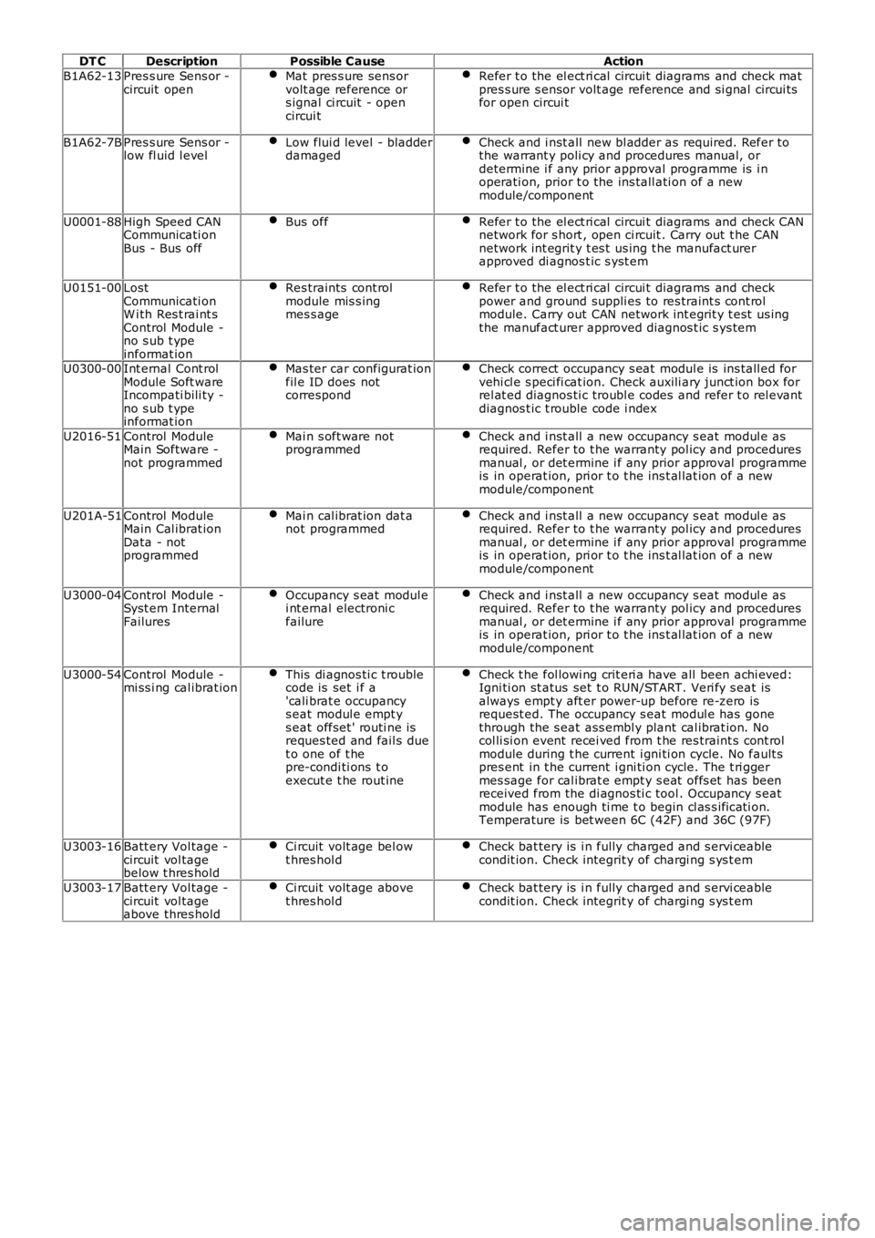
DT CDescriptionPossible CauseAction
B1A62-13Pres s ure Sens or -circuit openMat pres s ure sens orvolt age reference ors ignal ci rcuit - opencircui t
Refer t o the el ect ri cal circui t diagrams and check matpres s ure s ensor volt age reference and si gnal circui tsfor open circui t
B1A62-7BPres s ure Sens or -low fl uid l evelLow flui d level - bladderdamagedCheck and i nst all new bl adder as required. Refer tothe warrant y poli cy and procedures manual, ordetermine i f any prior approval programme is i noperati on, prior t o the ins tall ati on of a newmodule/component
U0001-88High Speed CANCommunicati onBus - Bus off
Bus offRefer t o the el ect ri cal circui t diagrams and check CANnetwork for s hort , open ci rcuit . Carry out t he CANnetwork int egrit y t es t us ing t he manufact urerapproved di agnos t ic s yst em
U0151-00LostCommunicati onW i th Res t rai nt sControl Module -no s ub t ypeinformat ion
Res traints cont rolmodule mis s ingmes s age
Refer t o the el ect ri cal circui t diagrams and checkpower and ground suppli es to res traint s cont rolmodule. Carry out CAN network int egrit y t est us ingthe manufact urer approved diagnos t ic s ys tem
U0300-00Int ernal Cont rolModule Soft wareIncompati bili ty -no s ub t ypeinformat ion
Mas ter car configurat ionfil e ID does notcorrespond
Check correct occupancy s eat modul e is ins tall ed forvehi cl e s peci fi cat ion. Check auxili ary junct ion box forrel at ed diagnos ti c troubl e codes and refer t o rel evantdiagnos t ic t rouble code i ndex
U2016-51Control ModuleMain Software -not programmed
Mai n s oft ware notprogrammedCheck and i nst all a new occupancy s eat modul e asrequired. Refer to t he warranty pol icy and proceduresmanual , or det ermine i f any prior approval programmeis in operat ion, pri or t o t he ins t al lat ion of a newmodule/component
U201A-51Control ModuleMain Cal ibrat ionData - notprogrammed
Mai n cal ibrat ion dat anot programmedCheck and i nst all a new occupancy s eat modul e asrequired. Refer to t he warranty pol icy and proceduresmanual , or det ermine i f any prior approval programmeis in operat ion, pri or t o t he ins t al lat ion of a newmodule/component
U3000-04Control Module -Syst em InternalFailures
Occupancy s eat modul ei nt ernal electroni cfailure
Check and i nst all a new occupancy s eat modul e asrequired. Refer to t he warranty pol icy and proceduresmanual , or det ermine i f any prior approval programmeis in operat ion, pri or t o t he ins t al lat ion of a newmodule/component
U3000-54Control Module -mi ss i ng cal ibrat ionThis di agnos ti c t roublecode is set i f a'cali brat e occupancys eat modul e empt ys eat offset ' routi ne isreques ted and fail s duet o one of t hepre-condi ti ons t oexecut e t he rout ine
Check t he fol lowi ng crit eri a have all been achi eved:Igni ti on st atus set t o RUN/START. Veri fy s eat isalways empt y aft er power-up before re-zero isrequest ed. The occupancy s eat modul e has gonethrough the s eat ass embl y plant cal ibrat ion. Nocol li si on event recei ved from t he res traint s cont rolmodule during t he current i gni ti on cycle. No fault spres ent in t he current i gni ti on cycle. The t ri ggermes sage for cal ibrat e empt y s eat offs et has beenreceived from the di agnos ti c tool . Occupancy s eatmodule has enough ti me t o begin cl as s ificati on.Temperature is bet ween 6C (42F) and 36C (97F)
U3003-16Batt ery Vol tage -circuit vol tagebelow t hres hold
Ci rcuit volt age bel owt hres hol dCheck bat tery is i n fully charged and s ervi ceablecondit ion. Check integrit y of chargi ng s ys t em
U3003-17Batt ery Vol tage -circuit vol tageabove thres hold
Ci rcuit volt age abovet hres hol dCheck bat tery is i n fully charged and s ervi ceablecondit ion. Check integrit y of chargi ng s ys t em
Page 118 of 3229
Publ is hed: 27-Apr-2011
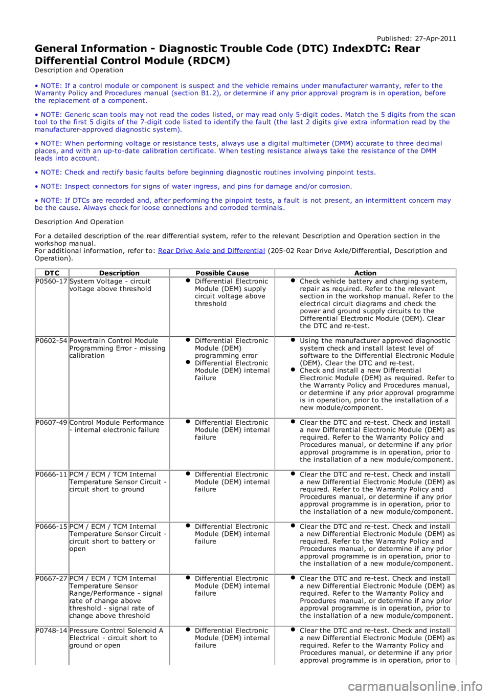
General Information - Diagnostic Trouble Code (DTC) IndexDTC: Rear
Differential Control Module (RDCM)
Des cript ion and Operat ion
• NOTE: If a cont rol module or component i s s uspect and the vehicl e remai ns under manufacturer warrant y, refer t o t heW arranty Pol icy and Procedures manual (s ect ion B1.2), or determine i f any pri or approval program is i n operat ion, beforet he replacement of a component.
• NOTE: Generic scan t ool s may not read the codes li st ed, or may read only 5-digi t codes . Match t he 5 digi ts from t he s cant ool t o t he fi rs t 5 di gi ts of the 7-digit code li s ted t o i dent ify the fault (the last 2 digi ts gi ve ext ra informati on read by themanufacturer-approved di agnos ti c s ys t em).
• NOTE: W hen performing volt age or res is t ance t est s , always use a digi tal mult imeter (DMM) accurat e t o t hree deci malplaces, and wi th an up-t o-date cal ibrat ion cert ificate. W hen tes ti ng res is t ance al ways take t he res is t ance of t he DMMleads i nt o account .
• NOTE: Check and recti fy bas ic faul ts before beginni ng diagnos t ic rout ines i nvol vi ng pinpoint t es t s.
• NOTE: Ins pect connect ors for s igns of water ingres s , and pins for damage and/or corros ion.
• NOTE: If DTCs are recorded and, aft er performi ng the pi npoi nt tes ts , a fault is not present , an int ermi tt ent concern maybe t he caus e. Always check for loose connect ions and corroded terminals .
Des cript ion And Operat ion
For a detail ed descripti on of the rear different ial sys t em, refer t o t he rel evant Des cript ion and Operat ion s ecti on in theworks hop manual .For addit ional informat ion, refer t o: Rear Drive Axl e and Different ial (205-02 Rear Drive Axl e/Different ial , Des cri pti on andOperat ion).
DT CDescriptionPossible CauseActionP0560-17Syst em Vol tage - circui tvolt age above t hres hol dDi fferenti al El ect ronicModule (DEM) s uppl ycircui t vol tage abovet hres hol d
Check vehi cl e batt ery and chargi ng s ys t em,repai r as required. Refer to the relevants ecti on in the workshop manual. Refer t o t heel ect ri cal circui t diagrams and check thepower and ground s uppl y circui ts t o t heDi fferenti al El ect roni c Modul e (DEM). Cleart he DTC and re-t es t.
P0602-54Powert rain Cont rol ModuleProgramming Error - mi s si ngcal ibrat ion
Di fferenti al El ect ronicModule (DEM)programming errorDi fferenti al El ect ronicModule (DEM) i nt ernalfailure
Us i ng the manufact urer approved diagnos t ics ys tem check and i ns t all lat est l evel ofs oftware to the Different ial Elect roni c Modul e(DEM). Cl ear the DTC and re-t es t.Check and ins t al l a new Di fferenti alEl ect ronic Modul e (DEM) as required. Refer t ot he W arrant y Policy and Procedures manual,or det ermi ne if any pri or approval programmei s i n operati on, prior t o the ins tall ati on of anew modul e/component .
P0607-49Control Module Performance- int ernal electroni c fai lureDi fferenti al El ect ronicModule (DEM) i nt ernalfailure
Cl ear t he DTC and re-t es t. Check and ins talla new Different ial Elect ronic Module (DEM) asrequi red. Refer t o t he W arranty Pol icy andProcedures manual, or determine if any pri orapproval programme is in operat ion, pri or t ot he i ns t allat ion of a new module/component .
P0666-11PCM / ECM / TCM InternalTemperature Sensor Ci rcuit -circuit short to ground
Di fferenti al El ect ronicModule (DEM) i nt ernalfailure
Cl ear t he DTC and re-t es t. Check and ins talla new Different ial Elect ronic Module (DEM) asrequi red. Refer t o t he W arranty Pol icy andProcedures manual, or determine if any pri orapproval programme is in operat ion, pri or t ot he i ns t allat ion of a new module/component .
P0666-15PCM / ECM / TCM InternalTemperature Sensor Ci rcuit -circuit short to bat tery oropen
Di fferenti al El ect ronicModule (DEM) i nt ernalfailure
Cl ear t he DTC and re-t es t. Check and ins talla new Different ial Elect ronic Module (DEM) asrequi red. Refer t o t he W arranty Pol icy andProcedures manual, or determine if any pri orapproval programme is in operat ion, pri or t ot he i ns t allat ion of a new module/component .
P0667-27PCM / ECM / TCM InternalTemperature SensorRange/Performance - s ignalrat e of change abovet hreshol d - s ignal rate ofchange above threshold
Di fferenti al El ect ronicModule (DEM) i nt ernalfailure
Cl ear t he DTC and re-t es t. Check and ins talla new Different ial Elect ronic Module (DEM) asrequi red. Refer t o t he W arranty Pol icy andProcedures manual, or determine if any pri orapproval programme is in operat ion, pri or t ot he i ns t allat ion of a new module/component .
P0748-14Pres s ure Control Sol enoi d AElectrical - ci rcuit s hort t oground or open
Di fferenti al El ect ronicModule (DEM) i nt ernalfailure
Cl ear t he DTC and re-t es t. Check and ins talla new Different ial Elect ronic Module (DEM) asrequi red. Refer t o t he W arranty Pol icy andProcedures manual, or determine if any pri orapproval programme is in operat ion, pri or t o
Page 120 of 3229
DT CDescriptionPossible CauseAction
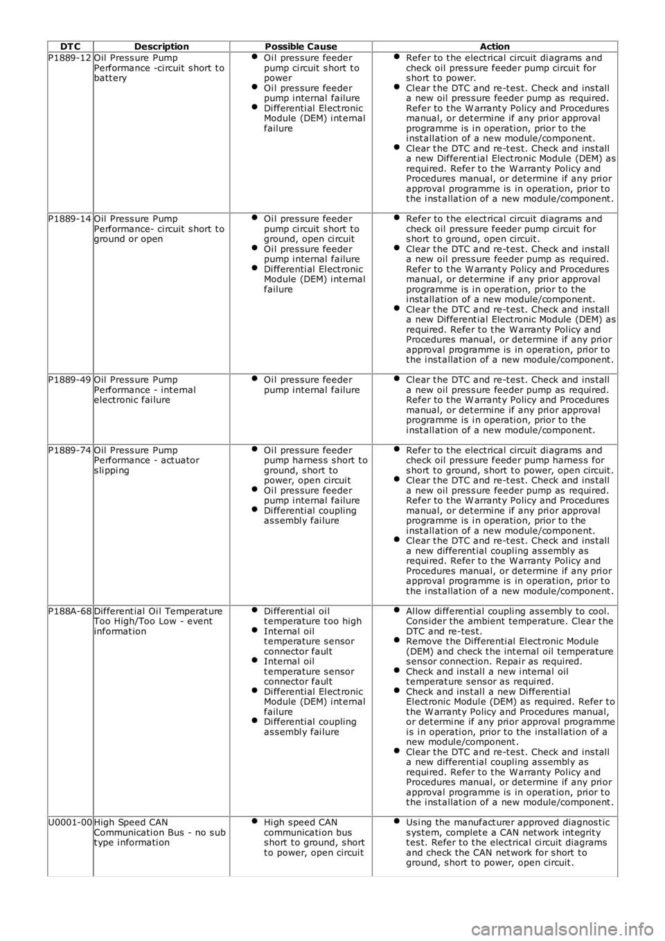
P1889-12Oil Press ure PumpPerformance -ci rcuit s hort t obatt ery
Oi l pres sure feederpump ci rcuit s hort t opowerOi l pres sure feederpump i nternal failureDi fferenti al El ect ronicModule (DEM) i nt ernalfailure
Refer to t he elect rical circuit di agrams andcheck oil pres s ure feeder pump circui t fors hort t o power.Cl ear t he DTC and re-t es t. Check and ins talla new oil pres s ure feeder pump as required.Refer to t he W arrant y Policy and Proceduresmanual, or det ermi ne if any pri or approvalprogramme is i n operati on, prior t o t hei nst all ati on of a new module/component.Cl ear t he DTC and re-t es t. Check and ins talla new Different ial Elect ronic Module (DEM) asrequi red. Refer t o t he W arranty Pol icy andProcedures manual, or determine if any pri orapproval programme is in operat ion, pri or t ot he i ns t allat ion of a new module/component .
P1889-14Oil Press ure PumpPerformance- ci rcuit s hort t oground or open
Oi l pres sure feederpump ci rcuit s hort t oground, open ci rcuitOi l pres sure feederpump i nternal failureDi fferenti al El ect ronicModule (DEM) i nt ernalfailure
Refer to t he elect rical circuit di agrams andcheck oil pres s ure feeder pump circui t fors hort t o ground, open circuit .Cl ear t he DTC and re-t es t. Check and ins talla new oil pres s ure feeder pump as required.Refer to t he W arrant y Policy and Proceduresmanual, or det ermi ne if any pri or approvalprogramme is i n operati on, prior t o t hei nst all ati on of a new module/component.Cl ear t he DTC and re-t es t. Check and ins talla new Different ial Elect ronic Module (DEM) asrequi red. Refer t o t he W arranty Pol icy andProcedures manual, or determine if any pri orapproval programme is in operat ion, pri or t ot he i ns t allat ion of a new module/component .
P1889-49Oil Press ure PumpPerformance - int ernalelectroni c fai lure
Oi l pres sure feederpump i nternal failureCl ear t he DTC and re-t es t. Check and ins talla new oil pres s ure feeder pump as required.Refer to t he W arrant y Policy and Proceduresmanual, or det ermi ne if any pri or approvalprogramme is i n operati on, prior t o t hei nst all ati on of a new module/component.
P1889-74Oil Press ure PumpPerformance - act uators li ppi ng
Oi l pres sure feederpump harnes s s hort t oground, s hort topower, open circui tOi l pres sure feederpump i nternal failureDi fferenti al couplingas s embl y fai lure
Refer to t he elect rical circuit di agrams andcheck oil pres s ure feeder pump harnes s fors hort t o ground, s hort t o power, open circuit .Cl ear t he DTC and re-t es t. Check and ins talla new oil pres s ure feeder pump as required.Refer to t he W arrant y Policy and Proceduresmanual, or det ermi ne if any pri or approvalprogramme is i n operati on, prior t o t hei nst all ati on of a new module/component.Cl ear t he DTC and re-t es t. Check and ins talla new different ial coupl ing as s embl y asrequi red. Refer t o t he W arranty Pol icy andProcedures manual, or determine if any pri orapproval programme is in operat ion, pri or t ot he i ns t allat ion of a new module/component .
P188A-68Different ial Oi l Temperat ureToo High/Too Low - eventinformat ion
Di fferenti al oi lt emperature t oo highInternal oilt emperature s ensorconnector faul tInternal oilt emperature s ensorconnector faul tDi fferenti al El ect ronicModule (DEM) i nt ernalfailureDi fferenti al couplingas s embl y fai lure
Al low di fferenti al coupli ng ass embly to cool.Cons ider the ambient temperat ure. Clear t heDTC and re-tes t.Remove t he Di fferenti al El ect ronic Module(DEM) and check t he int ernal oil t emperatures ens or connect ion. Repai r as required.Check and ins t al l a new i nternal oilt emperat ure s ens or as requi red.Check and ins t al l a new Di fferenti alEl ect ronic Modul e (DEM) as required. Refer t ot he W arrant y Policy and Procedures manual,or det ermi ne if any pri or approval programmei s i n operati on, prior t o the ins tall ati on of anew modul e/component .Cl ear t he DTC and re-t es t. Check and ins talla new different ial coupl ing as s embl y asrequi red. Refer t o t he W arranty Pol icy andProcedures manual, or determine if any pri orapproval programme is in operat ion, pri or t ot he i ns t allat ion of a new module/component .
U0001-00High Speed CANCommunicati on Bus - no s ubt ype i nformati on
Hi gh s peed CANcommunicati on buss hort t o ground, s hortt o power, open circui t
Us i ng the manufact urer approved diagnos t ics ys tem, complet e a CAN net work int egrit yt es t. Refer t o t he electrical ci rcuit diagramsand check the CAN net work for s hort t oground, s hort t o power, open circuit .
Page 121 of 3229
DT CDescriptionPossible CauseAction
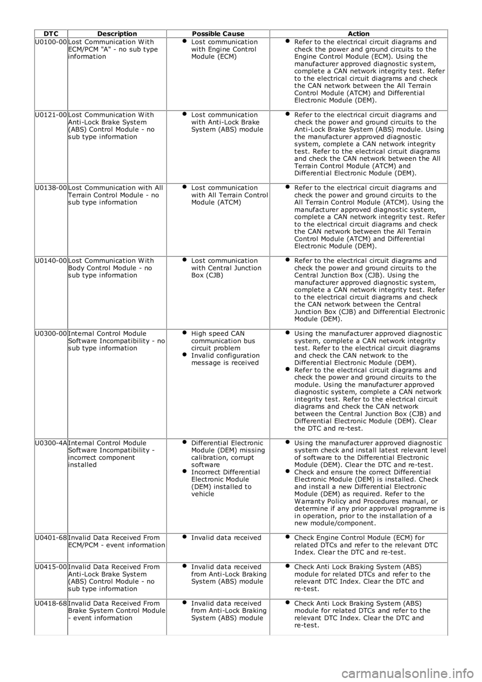
U0100-00Lost Communi cat ion W it hECM/PCM "A" - no sub t ypeinformat ion
Los t communi cat ionwi th Engi ne Cont rolModule (ECM)
Refer to t he elect rical circuit di agrams andcheck the power and ground circui ts to t heEngine Cont rol Module (ECM). Us ing themanufact urer approved diagnos t ic s yst em,complet e a CAN network int egrit y t es t . Refert o t he electrical ci rcuit di agrams and checkt he CAN net work bet ween the Al l Terrai nCont rol Modul e (ATCM) and Different ialEl ect ronic Modul e (DEM).
U0121-00Lost Communi cat ion W it hAnti -Lock Brake Syst em(ABS) Control Modul e - nos ub type i nformati on
Los t communi cat ionwi th Ant i-Lock BrakeSys tem (ABS) module
Refer to t he elect rical circuit di agrams andcheck the power and ground circui ts to t heAnt i-Lock Brake Sys t em (ABS) modul e. Us i ngt he manufact urer approved di agnos ti cs ys tem, complet e a CAN net work int egrit yt es t. Refer t o t he electrical ci rcuit diagramsand check the CAN net work bet ween t he AllTerrain Cont rol Module (ATCM) andDi fferenti al El ect roni c Modul e (DEM).
U0138-00Lost Communi cat ion wi th AllTerrai n Control Modul e - nos ub type i nformati on
Los t communi cat ionwi th All Terrai n ControlModule (ATCM)
Refer to t he elect rical circuit di agrams andcheck the power and ground circui ts to t heAl l Terrai n Control Module (ATCM). Usi ng t hemanufact urer approved diagnos t ic s yst em,complet e a CAN network int egrit y t es t . Refert o t he electrical ci rcuit di agrams and checkt he CAN net work bet ween the Al l Terrai nCont rol Modul e (ATCM) and Different ialEl ect ronic Modul e (DEM).
U0140-00Lost Communi cat ion W it hBody Cont rol Module - nos ub type i nformati on
Los t communi cat ionwi th Cent ral Junct ionBox (CJB)
Refer to t he elect rical circuit di agrams andcheck the power and ground circui ts to t heCent ral Juncti on Box (CJB). Usi ng themanufact urer approved diagnos t ic s yst em,complet e a CAN network int egrit y t es t . Refert o t he electrical ci rcuit di agrams and checkt he CAN net work bet ween the Cent ralJunct ion Box (CJB) and Different ial Electroni cModule (DEM).
U0300-00Int ernal Cont rol ModuleSoft ware Incompat ibi lit y - nos ub type i nformati on
Hi gh s peed CANcommunicati on buscircui t problemInval id confi gurati onmes s age is recei ved
Us i ng the manufact urer approved diagnos t ics ys tem, complet e a CAN net work int egrit yt es t. Refer t o t he electrical ci rcuit diagramsand check the CAN net work to theDi fferenti al El ect roni c Modul e (DEM).Refer to t he elect rical circuit di agrams andcheck the power and ground circui ts to t hemodul e. Us i ng the manufact urer approveddi agnos ti c s ys t em, compl ete a CAN net worki ntegri ty tes t. Refer to t he elect rical circuitdi agrams and check t he CAN net workbet ween the Cent ral Juncti on Box (CJB) andDi fferenti al El ect roni c Modul e (DEM). Cleart he DTC and re-t es t.
U0300-4AInt ernal Cont rol ModuleSoft ware Incompat ibi lit y -incorrect componentins t al led
Di fferenti al El ect ronicModule (DEM) mi s si ngcali brati on, corrupts oft wareIncorrect Different ialElect ronic Module(DEM) ins tal led t ovehicle
Us i ng the manufact urer approved diagnos t ics ys tem check and i ns t all lat est relevant l evelof s oft ware to the Di fferenti al El ect ronicModule (DEM). Clear the DTC and re-tes t .Check and ensure t he correct Different ialEl ect ronic Modul e (DEM) i s i ns t alled. Checkand i nst all a new Different ial Electroni cModule (DEM) as requi red. Refer t o t heW arrant y Poli cy and Procedures manual , ordet ermi ne if any prior approval programme i si n operat ion, prior t o t he ins t al lat ion of anew modul e/component .
U0401-68Invali d Dat a Recei ved FromECM/PCM - event i nformat ionInval id dat a receivedCheck Engi ne Control Module (ECM) forrelat ed DTCs and refer t o t he rel evant DTCIndex. Cl ear t he DTC and re-t est .
U0415-00Invali d Dat a Recei ved FromAnti -Lock Brake Syst em(ABS) Control Modul e - nos ub type i nformati on
Inval id dat a receivedfrom Anti -Lock BrakingSys tem (ABS) module
Check Anti Lock Braking Sys tem (ABS)modul e for related DTCs and refer t o t herelevant DTC Index. Clear the DTC andre-t es t.
U0418-68Invali d Dat a Recei ved FromBrake Sys tem Cont rol Module- event i nformati on
Inval id dat a receivedfrom Anti -Lock BrakingSys tem (ABS) module
Check Anti Lock Braking Sys tem (ABS)modul e for related DTCs and refer t o t herelevant DTC Index. Clear the DTC andre-t es t.
Page 123 of 3229
Publi s hed: 04-May-2011
General Information - Diagnostic Trouble Code (DTC) IndexDTC: Parking
Aid Module (PAM)
Des cript ion and Operat ion
• NOTE: If a cont rol module or component i s s uspect and the vehicl e remai ns under manufacturer warrant y, refer t o t heW arranty Pol icy and Procedures manual (s ect ion B1.2), or determine i f any pri or approval program is i n operat ion, beforet he replacement of a component.
• NOTE: Generic scan t ool s may not read the codes li st ed, or may read only 5-digi t codes . Match t he 5 digi ts from t he s cant ool t o t he fi rs t 5 di gi ts of the 7-digit code li s ted t o i dent ify the fault (the last 2 digi ts gi ve ext ra informati on read by themanufacturer-approved di agnos ti c s ys t em).
• NOTE: W hen performing volt age or res is t ance t est s , always use a digi tal mult imeter (DMM) accurat e t o t hree deci malplaces, and wi th an up-t o-date cal ibrat ion cert ificate. W hen tes ti ng res is t ance al ways take t he res is t ance of t he DMMleads i nt o account .
• NOTE: Check and recti fy bas ic faul ts before beginni ng diagnos t ic rout ines i nvol vi ng pinpoint t es t s.
• NOTE: Ins pect connect ors for s igns of water ingres s , and pins for damage and/or corros ion.
• NOTE: If DTCs are recorded and, aft er performi ng the pi npoi nt tes ts , a fault is not present , an int ermi tt ent concern maybe t he caus e. Always check for loose connect ions and corroded terminals .
Des cript ion And Operat ion
For a detail ed descripti on of the parki ng as si s t cont rol s ys t em, refer t o t he rel evant Des cript ion and Operat ion secti on int he works hop manual .For addit ional informat ion, refer t o: Parking Ai d (413-13 Parking Ai d, Des cri pti on and Operati on).
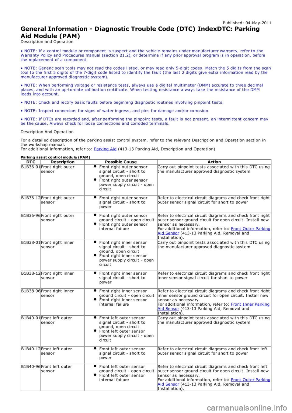
Parking assist control module (PAM)DT CDescriptionPossible CauseAction
B1B36-01Front ri ght out ers ens orFront ri ght out er sens ors ignal circui t - s hort t oground, open circui tFront ri ght out er sens orpower s upply circui t - openci rcuit
Carry out pinpoint t est s as s oci at ed wi th this DTC usi ngt he manufact urer approved di agnos ti c s ys t em
B1B36-12Front ri ght out ers ens orFront ri ght out er sens ors ignal circui t - s hort t opower
Refer to el ect ri cal circui t diagrams and check front rightout er sens or si gnal circui t for s hort t o power
B1B36-96Front ri ght out ers ens orFront ri ght out er sens orground circuit - open ci rcuitFront ri ght out er sens orint ernal fail ure
Refer to el ect ri cal circui t diagrams and check front rightout er sens or ground ci rcuit for open ci rcuit . Ins tal l news ens or as necess ary.For addit ional i nformati on, refer to: Front Out er ParkingAi d Sensor (413-13 Parking Ai d, Removal andIns tall ati on).
B1B38-01Front ri ght inners ens orFront ri ght i nner s ens ors ignal circui t - s hort t oground, open circui tFront ri ght i nner s ens orpower s upply circui t - openci rcuit
Carry out pinpoint t est s as s oci at ed wi th this DTC usi ngt he manufact urer approved di agnos ti c s ys t em
B1B38-12Front ri ght inners ens orFront ri ght i nner s ens ors ignal circui t - s hort t opower
Refer to el ect ri cal circui t diagrams and check front righti nner s ens or s i gnal circuit for s hort to power
B1B38-96Front ri ght inners ens orFront ri ght i nner s ens orground circuit - open ci rcuitFront ri ght i nner s ens orint ernal fail ure
Refer to el ect ri cal circui t diagrams and check front righti nner s ens or ground ci rcuit for open circui t. Ins tall news ens or as necess ary.For addit ional i nformati on, refer to: Front Inner Parki ngAi d Sensor (413-13 Parking Ai d, Removal andIns tall ati on).B1B40-01Front left out ers ens orFront left out er sens ors ignal circui t - s hort t oground, open circui tFront left out er sens orpower s upply circui t - openci rcuit
Carry out pinpoint t est s as s oci at ed wi th this DTC usi ngt he manufact urer approved di agnos ti c s ys t em
B1B40-12Front left out ers ens orFront left out er sens ors ignal circui t - s hort t opower
Refer to el ect ri cal circui t diagrams and check front l eftout er sens or si gnal circui t for s hort t o power
B1B40-96Front left out ers ens orFront left out er sens orground circuit - open ci rcuitFront left out er sens orint ernal fail ure
Refer to el ect ri cal circui t diagrams and check front l eftout er sens or ground ci rcuit for open ci rcuit . Ins tal l news ens or as necess ary.For addit ional i nformati on, refer to: Front Out er ParkingAi d Sensor (413-13 Parking Ai d, Removal andIns tall ati on).
Page 124 of 3229
DT CDescriptionPossible CauseAction
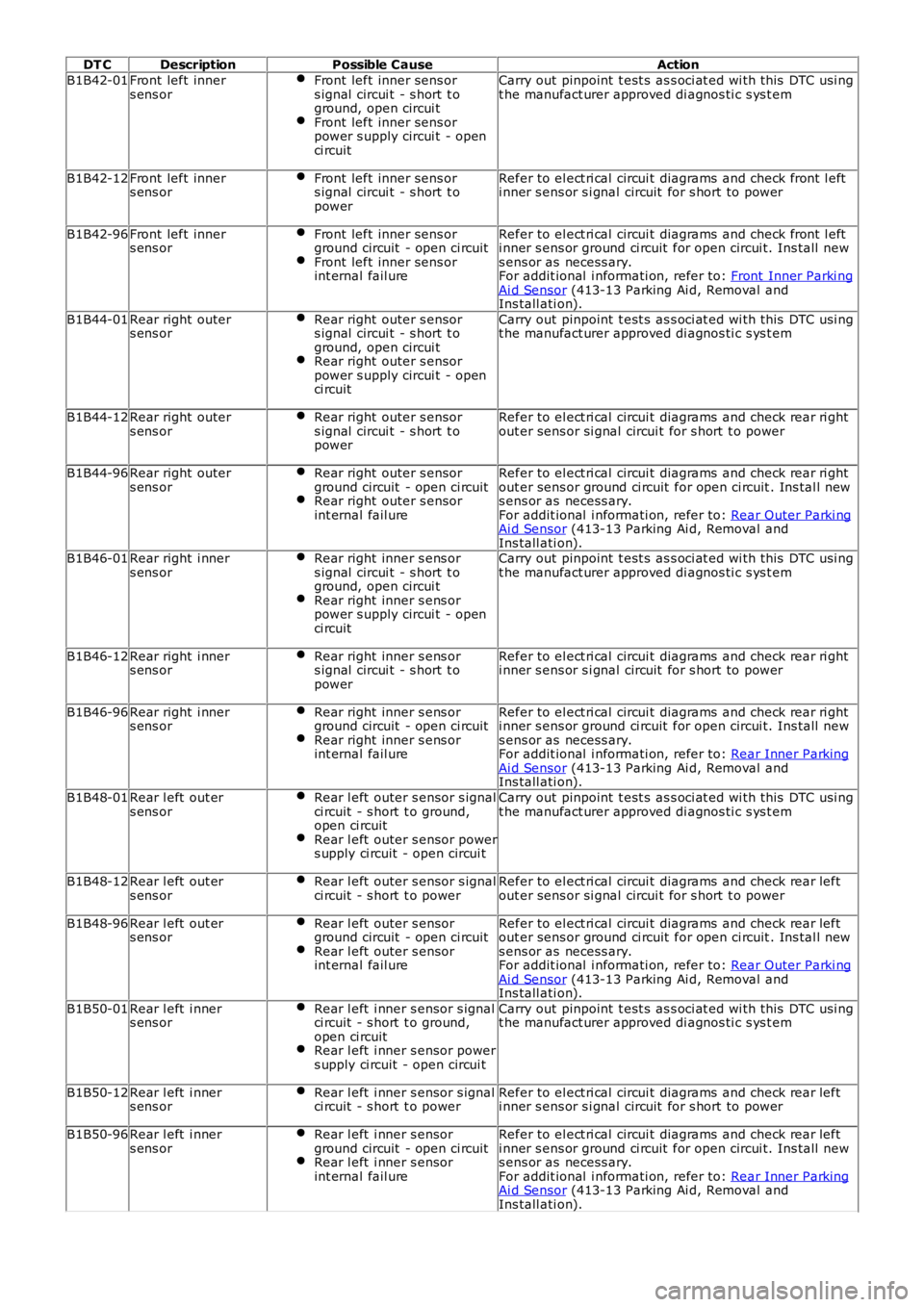
B1B42-01Front left inners ens orFront left inner sens ors ignal circui t - s hort t oground, open circui tFront left inner sens orpower s upply circui t - openci rcuit
Carry out pinpoint t est s as s oci at ed wi th this DTC usi ngt he manufact urer approved di agnos ti c s ys t em
B1B42-12Front left inners ens orFront left inner sens ors ignal circui t - s hort t opower
Refer to el ect ri cal circui t diagrams and check front l efti nner s ens or s i gnal circuit for s hort to power
B1B42-96Front left inners ens orFront left inner sens orground circuit - open ci rcuitFront left inner sens orint ernal fail ure
Refer to el ect ri cal circui t diagrams and check front l efti nner s ens or ground ci rcuit for open circui t. Ins tall news ens or as necess ary.For addit ional i nformati on, refer to: Front Inner Parki ngAi d Sensor (413-13 Parking Ai d, Removal andIns tall ati on).
B1B44-01Rear right outers ens orRear right outer s ensors ignal circui t - s hort t oground, open circui tRear right outer s ensorpower s upply circui t - openci rcuit
Carry out pinpoint t est s as s oci at ed wi th this DTC usi ngt he manufact urer approved di agnos ti c s ys t em
B1B44-12Rear right outers ens orRear right outer s ensors ignal circui t - s hort t opower
Refer to el ect ri cal circui t diagrams and check rear ri ghtout er sens or si gnal circui t for s hort t o power
B1B44-96Rear right outers ens orRear right outer s ensorground circuit - open ci rcuitRear right outer s ensorint ernal fail ure
Refer to el ect ri cal circui t diagrams and check rear ri ghtout er sens or ground ci rcuit for open ci rcuit . Ins tal l news ens or as necess ary.For addit ional i nformati on, refer to: Rear Outer Parki ngAi d Sensor (413-13 Parking Ai d, Removal andIns tall ati on).B1B46-01Rear right i nners ens orRear right inner s ens ors ignal circui t - s hort t oground, open circui tRear right inner s ens orpower s upply circui t - openci rcuit
Carry out pinpoint t est s as s oci at ed wi th this DTC usi ngt he manufact urer approved di agnos ti c s ys t em
B1B46-12Rear right i nners ens orRear right inner s ens ors ignal circui t - s hort t opower
Refer to el ect ri cal circui t diagrams and check rear ri ghti nner s ens or s i gnal circuit for s hort to power
B1B46-96Rear right i nners ens orRear right inner s ens orground circuit - open ci rcuitRear right inner s ens orint ernal fail ure
Refer to el ect ri cal circui t diagrams and check rear ri ghti nner s ens or ground ci rcuit for open circui t. Ins tall news ens or as necess ary.For addit ional i nformati on, refer to: Rear Inner ParkingAi d Sensor (413-13 Parking Ai d, Removal andIns tall ati on).
B1B48-01Rear l eft out ers ens orRear l eft outer s ensor s ignalci rcuit - s hort t o ground,open ci rcuitRear l eft outer s ensor powers upply ci rcuit - open circui t
Carry out pinpoint t est s as s oci at ed wi th this DTC usi ngt he manufact urer approved di agnos ti c s ys t em
B1B48-12Rear l eft out ers ens orRear l eft outer s ensor s ignalci rcuit - s hort t o powerRefer to el ect ri cal circui t diagrams and check rear leftout er sens or si gnal circui t for s hort t o power
B1B48-96Rear l eft out ers ens orRear l eft outer s ensorground circuit - open ci rcuitRear l eft outer s ensorint ernal fail ure
Refer to el ect ri cal circui t diagrams and check rear leftout er sens or ground ci rcuit for open ci rcuit . Ins tal l news ens or as necess ary.For addit ional i nformati on, refer to: Rear Outer Parki ngAi d Sensor (413-13 Parking Ai d, Removal andIns tall ati on).
B1B50-01Rear l eft i nners ens orRear l eft i nner s ensor s ignalci rcuit - s hort t o ground,open ci rcuitRear l eft i nner s ensor powers upply ci rcuit - open circui t
Carry out pinpoint t est s as s oci at ed wi th this DTC usi ngt he manufact urer approved di agnos ti c s ys t em
B1B50-12Rear l eft i nners ens orRear l eft i nner s ensor s ignalci rcuit - s hort t o powerRefer to el ect ri cal circui t diagrams and check rear lefti nner s ens or s i gnal circuit for s hort to power
B1B50-96Rear l eft i nners ens orRear l eft i nner s ensorground circuit - open ci rcuitRear l eft i nner s ensorint ernal fail ure
Refer to el ect ri cal circui t diagrams and check rear lefti nner s ens or ground ci rcuit for open circui t. Ins tall news ens or as necess ary.For addit ional i nformati on, refer to: Rear Inner ParkingAi d Sensor (413-13 Parking Ai d, Removal andIns tall ati on).