Page 3433 of 5267

INSTALLATION
CAUTION: The primary oil filter seal MUST be fully
installed flush against the oil pump body. DO NOT
install the seal onto the filter neck and attempt to
install the filter and seal as an assembly. Damage
to the transmission will result.
1. If necessary, install a new primary oil filter seal in
the oil pump inlet bore. Seat the seal in the bore
with a suitable tool (appropriately sized drift or
socket, the butt end of a hammer, or other suitable
tool).
2. Place replacement filter in position on valve body
and into the oil pump.
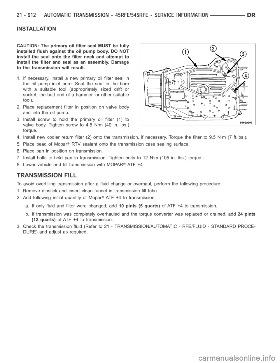
3. Install screw to hold the primary oil filter (1) to
valve body. Tighten screw to 4.5 Nꞏm (40 in. lbs.)
torque.
4. Install new cooler return filter (2) onto the transmission, if necessary. Torque the filter to 9.5 Nꞏm (7 ft.lbs.).
5. Place bead of Mopar
RTV sealant onto the transmission case sealing surface.
6. Place pan in position on transmission.
7. Install bolts to hold pan to transmission. Tighten bolts to 12 Nꞏm (105 in. lbs.) torque.
8. Lower vehicle and fill transmission with MOPAR
AT F + 4 .
TRANSMISSION FILL
To avoid overfilling transmission after a fluid change or overhaul, perform the following procedure:
1. Remove dipstick and insert clean funnel in transmission fill tube.
2. Add following initial quantity of Mopar
ATF+4totransmission:
a. If only fluid and filter were changed, add10 pints (5 quarts)of ATF +4 to transmission.
b. If transmission was completely overhauled and the torque converter wasreplaced or drained, add24 pints
(12 quarts)ofATF+4totransmission.
3. Check the transmission fluid (Refer to 21 - TRANSMISSION/AUTOMATIC - RFE/FLUID - STANDARD PROCE-
DURE) and adjust as required.
Page 3453 of 5267

SENSOR-INPUT SPEED
DESCRIPTION
The Input and Output Speed Sensors are two-wire magnetic pickup devices that generate AC signals as rotation
occurs. They are mounted in the left side of the transmission case and are considered primary inputs to the Trans-
mission Control Module (TCM).
OPERATION
The Input Speed Sensor provides information on how fast the input shaft is rotating. As the teeth of the input clutch
hub pass by the sensor coil, an AC voltage is generated and sent to the TCM. The TCM interprets this information
as input shaft rpm.
The Output Speed Sensor generates an AC signal in a similar fashion, thoughitscoilisexcitedbyrotationofthe
rear planetary carrier lugs. The TCM interprets this information as outputshaftrpm.
The TCM compares the input and output speed signals to determine the following:
Transmission gear ratio
Speed ratio error detection
CVI calculation
The TCM also compares the input speed signal and the engine speed signal to determine the following:
Torque converter clutch slippage
Torque converter element speed ratio
REMOVAL
1. Raise vehicle.
2. Place a suitable fluid catch pan under the transmis-
sion.
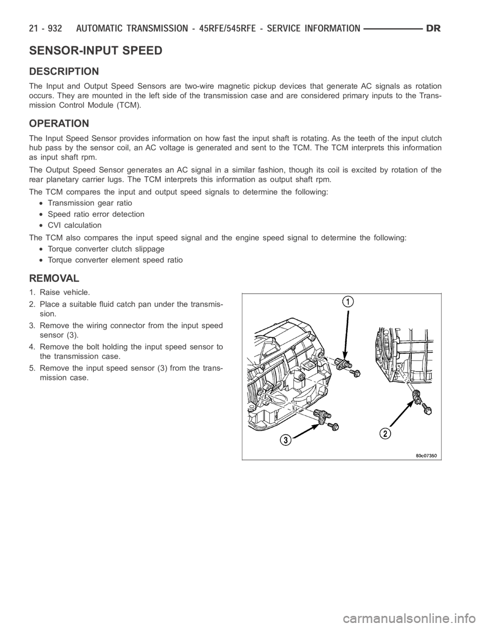
3. Remove the wiring connector from the input speed
sensor (3).
4. Remove the bolt holding the input speed sensor to
the transmission case.
5. Remove the input speed sensor (3) from the trans-
mission case.
Page 3455 of 5267

SENSOR-LINE PRESSURE
DESCRIPTION
The TCM utilizes a closed-loop system to control transmission line pressure. The system contains a variable force
style solenoid, the Pressure Control Solenoid, mounted on the side of the solenoid and pressure switch assembly.
The solenoid is duty cycle controlled by the TCM to vent the unnecessary line pressure supplied by the oil pump
back to the sump. The system also contains a variable pressure style sensor, the Line Pressure Sensor, which is a
direct input to the TCM. The line pressure solenoid monitors the transmission line pressure and completes the feed-
back loop to the TCM. The TCM uses this information to adjust its control of the pressure control solenoid to
achieve the desired line pressure.
OPERATION
The TCM calculates the desired line pressure based upon inputs from the transmission and engine. The TCM cal-
culates the torque input to the transmission and uses that information as the primary input to the calculation. The
line pressure is set to a predetermined value during shifts and when the transmission is in the PARK and NEUTRAL
positions. This is done to ensure consistent shift quality. During all other operation, the actual line pressure is com-
pared to the desired line pressure and adjustments are made to the pressurecontrol solenoid duty cycle.
REMOVAL
1. Raise vehicle.
2. Place a suitable fluid catch pan under the transmis-
sion.
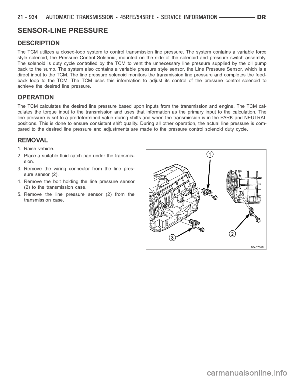
3. Remove the wiring connector from the line pres-
sure sensor (2).
4. Remove the bolt holding the line pressure sensor
(2) to the transmission case.
5. Remove the line pressure sensor (2) from the
transmission case.
Page 3461 of 5267
PUMP-OIL
DESCRIPTION
The oil pump (2) is located at the front of the trans-
mission inside the bell housing and behind the trans-
mission front cover.
The oil pump consists of two independent pumps.
Oil Pump Gears
1-PUMPHOUSING
2-DRIVEGEAR
3 - DRIVEN GEARS
Page 3462 of 5267
The oil pump also contains a number of valves. The
converter clutch switch (3) and control valves (2),
pressure regulator valve (5), and converter pressure
limit valve (6) are all located in the oil pump valve
body.
A front seal (2), and a bolt on reaction shaft (5) complete the oil pump assembly.
Oil Pump Reaction Shaft
1 - PUMP HOUSING 4 - SEAL RING (5)
2 - SEAL 5 - REACTION SHAFT SUPPORT
3 - OIL FILTER SEAL 6 - PUMP VALVE BODY
Page 3463 of 5267

OPERATION
As the torque converter rotates, the converter hub rotates the oil pump drive gear. As the drive gear rotates both
driven gears, a vacuum is created when the gear teeth come out of mesh. This suction draws fluid through the
pump inlet from the oil pan. As the gear teeth come back into mesh, pressurized fluid is forced into the pump outlet
and to the oil pump valves.
At low speeds, both sides of the pump supply fluid to the transmission. As the speed of the torque converter
increases, the flow from both sides increases until the flow from the primary side alone is sufficient to meet system
demands. At this point, the check valve located between the two pumps closes. The secondary side is shut down
and the primary side supplies all the fluid to the transmission.
CONVERTER CLUTCH SWITCH VALVE
The converter clutch switch valve is used to control the hydraulic pressure supplied to the front (OFF) side of the
torque converter clutch.
CONVERTER CLUTCH REGULATOR VALVE
The converter clutch regulator valve is used to control the hydraulic pressure supplied to the back (ON) side of the
torque converter clutch.
TORQUE CONVERTER LIMIT VALVE
The torque converter limit valve serves to limit the available line pressure to the torque converter clutch.
STANDARD PROCEDURE - OIL PUMP VOLUME CHECK
Measuring the oil pump output volume will determine if sufficient oil flowto the transmission oil cooler exists, and
whether or not an internal transmission failure is present.
Verify that the transmission fluid is at the proper level. Refer to the Fluid Level Check procedure in this section. If
necessary, fill the transmission to the proper level with Mopar
ATF +4, Automatic Transmission Fluid.
1. Disconnect theTo coolerline at the cooler inlet and place a collecting container under the disconnected line.
CAUTION: With the fluid set at the proper level, fluid collection should not exceed (1) quart or internal dam-
age to the transmission may occur.
2. Run the engineat 1800 rpm, with the shift selector in neutral. Verify that the transmission fluid temperature is
below 104.5° C (220° F) for this test.
3. If one quart of transmission fluid is collected in the container in 30 seconds or less, oil pump flow volume is
within acceptable limits. If fluid flow is intermittent, or it takes more than 30 seconds to collect one quart of fluid,
refer to the Hydraulic Pressure tests in this section for further diagnosis.
4. Re-connect theTo c o o l e rline to the transmission cooler inlet.
5. Refill the transmission to proper level.
Page 3464 of 5267
DISASSEMBLY
1. Remove the bolts holding the reaction shaft support (5) to the oil pump.
2. Remove the reaction shaft support (5) from the oil pump.
3. Remove all bolts holding the oil pump halves together.
4. Using suitable prying tools, separate the oil pump sections by inserting the tools in the supplied areas and prying
the halves apart.
NOTE: The oil pump halves are aligned to each other through the use of two dowels. Be sure to pry upward
evenly to prevent damage to the oil pump components.
Oil Pump Assembly
1 - PUMP HOUSING 4 - SEAL RING (5)
2 - SEAL 5 - REACTION SHAFT SUPPORT
3 - OIL FILTER SEAL 6 - PUMP VALVE BODY
Page 3465 of 5267
5. Remove the screws (7) holding the separator plate (1) onto the oil pump housing (4).
6. Remove the separator plate (1) from the oil pump housing (4).
7. Mark all gears for location. The gears are select fit and if the oil pump isto be reused, the gears must be
returned to their original locations.
8. Remove the oil pump gears (2, 6) from the oil pump housing (4).