2006 DODGE RAM SRT-10 oil
[x] Cancel search: oilPage 3363 of 5267
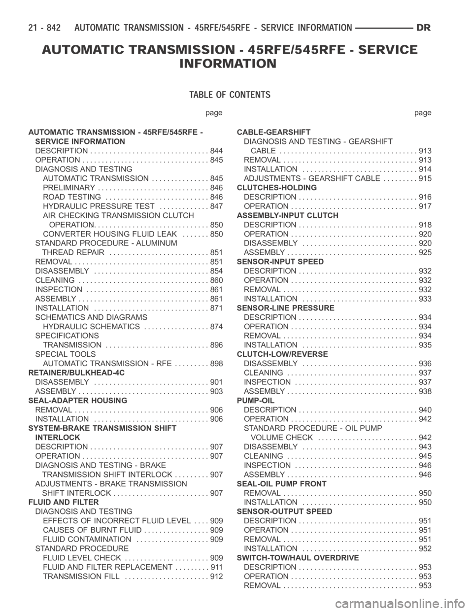
page page
AUTOMATIC TRANSMISSION - 45RFE/545RFE -
SERVICE INFORMATION
DESCRIPTION ............................... 844
OPERATION ................................. 845
DIAGNOSIS AND TESTING
AUTOMATIC TRANSMISSION ............... 845
PRELIMINARY ............................. 846
ROAD TESTING ........................... 846
HYDRAULIC PRESSURE TEST............. 847
AIR CHECKING TRANSMISSION CLUTCH
OPERATION............................... 850
CONVERTER HOUSING FLUID LEAK ....... 850
STANDARD PROCEDURE - ALUMINUM
THREAD REPAIR .......................... 851
REMOVAL ................................... 851
DISASSEMBLY .............................. 854
CLEANING .................................. 860
INSPECTION ................................ 861
ASSEMBLY .................................. 861
INSTALLATION .............................. 871
SCHEMATICS AND DIAGRAMS
HYDRAULIC SCHEMATICS ................. 874
SPECIFICATIONS
TRANSMISSION ........................... 896
SPECIAL TOOLS
AUTOMATIC TRANSMISSION - RFE ......... 898
RETAINER/BULKHEAD-4C
DISASSEMBLY .............................. 901
ASSEMBLY .................................. 903
SEAL-ADAPTER HOUSING
REMOVAL ................................... 906
INSTALLATION .............................. 906
SYSTEM-BRAKE TRANSMISSION SHIFT
INTERLOCK
DESCRIPTION ............................... 907
OPERATION ................................. 907
DIAGNOSIS AND TESTING - BRAKE
TRANSMISSION SHIFT INTERLOCK ......... 907
ADJUSTMENTS - BRAKE TRANSMISSION
SHIFT INTERLOCK ......................... 907
FLUID AND FILTER
DIAGNOSIS AND TESTING
EFFECTS OF INCORRECT FLUID LEVEL.... 909
CAUSES OF BURNT FLUID ................. 909
FLUID CONTAMINATION ................... 909
STANDARD PROCEDURE
FLUID LEVEL CHECK . ..................... 909
FLUID AND FILTER REPLACEMENT ......... 911
TRANSMISSION FILL ...................... 912CABLE-GEARSHIFT
DIAGNOSIS AND TESTING - GEARSHIFT
CABLE .................................... 913
REMOVAL ................................... 913
INSTALLATION .............................. 914
ADJUSTMENTS - GEARSHIFT CABLE ......... 915
CLUTCHES-HOLDING
DESCRIPTION ............................... 916
OPERATION ................................. 917
ASSEMBLY-INPUT CLUTCH
DESCRIPTION ............................... 918
OPERATION ................................. 920
DISASSEMBLY .............................. 920
ASSEMBLY .................................. 925
SENSOR-INPUT SPEED
DESCRIPTION ............................... 932
OPERATION ................................. 932
REMOVAL ................................... 932
INSTALLATION .............................. 933
SENSOR-LINE PRESSURE
DESCRIPTION ............................... 934
OPERATION ................................. 934
REMOVAL ................................... 934
INSTALLATION .............................. 935
CLUTCH-LOW/REVERSE
DISASSEMBLY .............................. 936
CLEANING .................................. 937
INSPECTION . . .............................. 937
ASSEMBLY .................................. 938
PUMP-OIL
DESCRIPTION ............................... 940
OPERATION ................................. 942
STANDARD PROCEDURE - OIL PUMP
VOLUME CHECK .......................... 942
DISASSEMBLY .............................. 943
CLEANING .................................. 945
INSPECTION . . .............................. 946
ASSEMBLY .................................. 946
SEAL-OIL PUMP FRONT
REMOVAL ................................... 950
INSTALLATION .............................. 950
SENSOR-OUTPUT SPEED
DESCRIPTION ............................... 951
OPERATION ................................. 951
REMOVAL ................................... 951
INSTALLATION .............................. 952
SWITCH-TOW/HAUL OVERDRIVE
DESCRIPTION ............................... 953
OPERATION ................................. 953
REMOVAL ................................... 953
Page 3365 of 5267
AUTOMATIC TRANSMISSION - 45RFE/545RFE-SERVICEINFORMATION
DESCRIPTION
The 45RFE/545RFE automatic transmissions is a sophisticated, multi-range, electronically controlled transmission
which combines optimized gear ratios for responsive performance, state of the art efficiency features and low NVH.
Other features include driver adaptive shifting and three planetary gearsets to provide wide ratio capability with
precise ratio steps for optimum driveability. The three planetary gear sets also make available a unique alternate
second gear ratio. The primary 2nd gear ratio fits between 1st and 3rd gearsfor normal through-gear accelerations.
The alternate second gear ratio (2prime) allows smoother 4-2 kickdowns athigh speeds to provide 2nd gear pass-
ing performance over a wider highway cruising range.
The hydraulic portion of the transmission consists of the transmission fluid, fluid passages, hydraulic valves, and
various line pressure control components.
The primary mechanical components of the transmission consist of the following:
Three multiple disc input clutches
Three multiple disc holding clutches
Five hydraulic accumulators
Three planetary gear sets
Dual Stage Hydraulic oil pump
Valve body
Solenoid pack
The Transmission Control Module (TCM) is the “heart” or “brain” of the electronic control system and relies on infor-
mation from various direct and indirect inputs (sensors, switches, etc.)to determine driver demand and vehicle oper-
ating conditions. Depending on the vehicle configuration, the TCM may be astandalone module or it it may be
housed along with the Powertrain Control Module (PCM) in a single module. With this information, the TCM can
calculate and perform timely and quality shifts through various output orcontrol devices (solenoid pack, transmission
control relay, etc.).
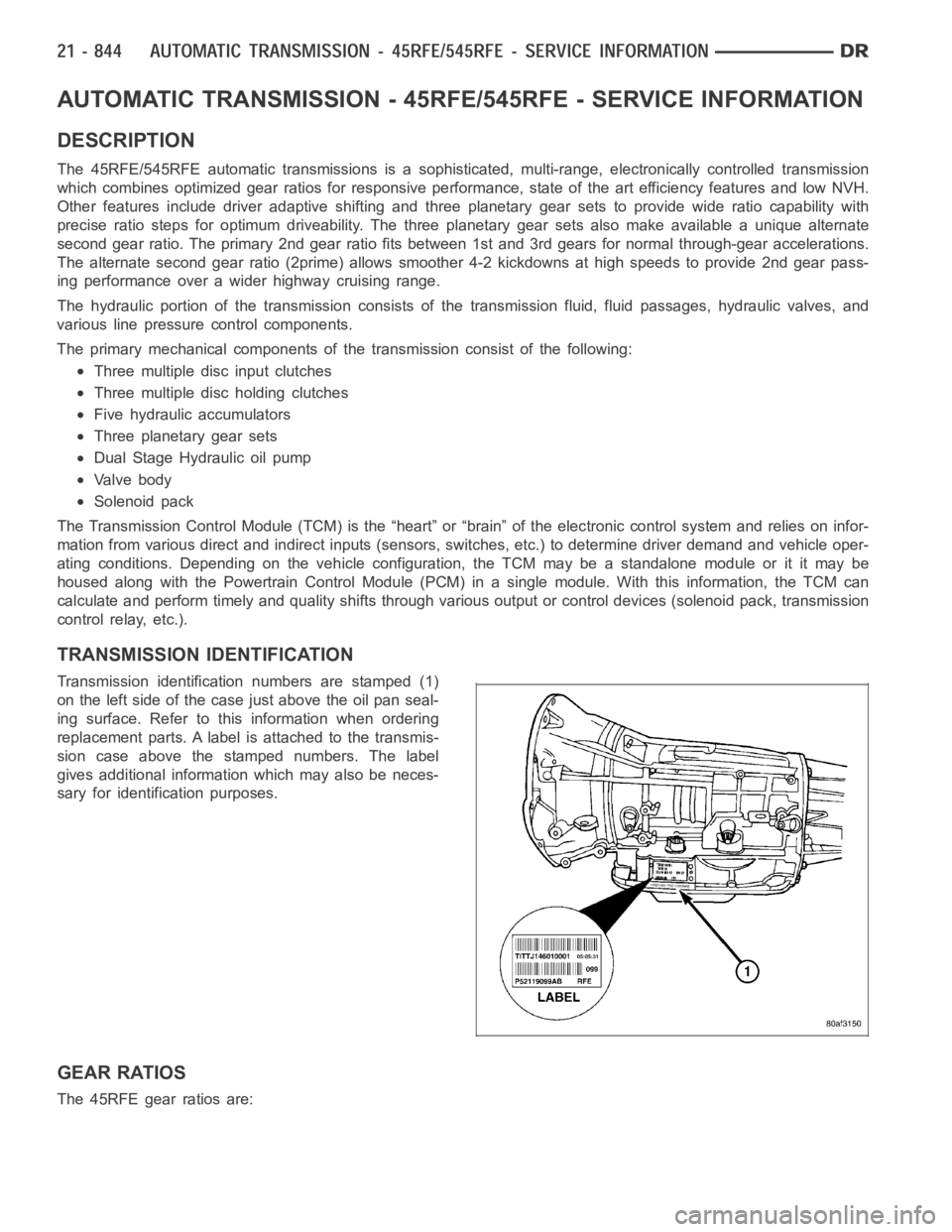
TRANSMISSION IDENTIFICATION
Transmission identification numbers are stamped (1)
on the left side of the case just above the oil pan seal-
ing surface. Refer to this information when ordering
replacement parts. A label is attached to the transmis-
sion case above the stamped numbers. The label
gives additional information which may also be neces-
sary for identification purposes.
GEAR RATIOS
The 45RFE gear ratios are:
Page 3367 of 5267
Improper adjustments
Hydraulic malfunctions
Mechanical malfunctions
Electronic malfunctions
Diagnosis of these problems should always begin by checking the easily accessible variables: fluid level and con-
dition, gearshift cable adjustment. Then perform a road test to determineif the problem has been corrected or if
more diagnosis is necessary. If the problem persists after the preliminary tests and corrections are completed,
hydraulic pressure checks should be performed.
PRELIMINARY
Two basic procedures are required. One procedure for vehicles that are drivable and an alternate procedure for
disabled vehicles (will not back up or move forward).
VEHICLE IS DRIVABLE
1. Check for transmission fault codes using scan tool.
2. Check fluid level and condition.
3. Adjust gearshift cable if complaint was based on delayed, erratic, or harsh shifts.
4. Road test and note how transmission upshifts, downshifts, and engages.
5. Perform hydraulic pressure test if shift problems were noted during roadtest.
6. Perform air-pressure test to check clutch operation.
VEHICLE IS DISABLED
1. Check fluid level and condition.
2. Check for broken or disconnected gearshift cable.
3. Check for cracked, leaking cooler lines, or loose or missing pressure-port plugs.
4. Raise and support vehicle on safety stands, start engine, shift transmission into gear, and note following:
a. If propeller shaft turns but wheels do not, problem is with differentialor axle shafts.
b. If propeller shaft does not turn and transmission is noisy, stop engine.Remove oil pan, and check for debris.
If pan is clear, remove transmission and check for damaged driveplate, converter, oil pump, or input shaft.
c. If propeller shaft does not turn and transmission is not noisy, perform hydraulic-pressure test to determine if
problem is hydraulic or mechanical.
ROAD TESTING
Before road testing, be sure the fluid level and control cable adjustmentshave been checked and adjusted if nec-
essary. Verify that all diagnostic trouble codes have been resolved.
Observe engine performance during the road test. A poorly tuned engine will not allow accurate analysis of trans-
mission operation.
Operate the transmission in all gear ranges. Check for shift variations and engine flare which indicates slippage.
Note if shifts are harsh, spongy, delayed, early, or if part throttle downshifts are sensitive.
Slippage indicated by engine flare, usually means clutch, overrunning clutch, or line pressure problems.
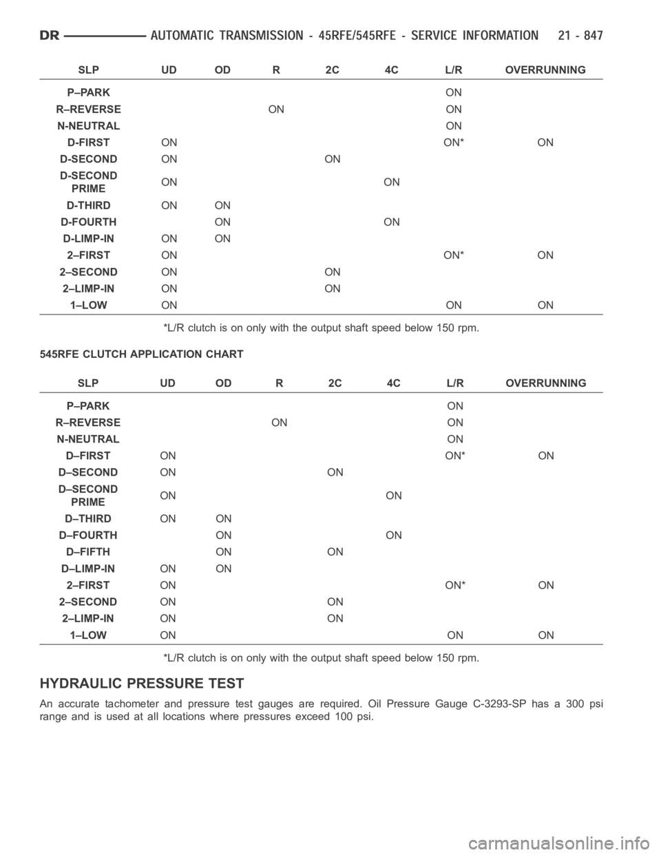
A slipping clutch can often be determined by comparing which internal units are applied in the various gear ranges.
The Clutch Application charts provide a basis for analyzing road test results.
45RFE CLUTCH APPLICATION CHART
Page 3368 of 5267
SLP UD OD R 2C 4C L/R OVERRUNNING
P–PARKON
R–REVERSEON ON
N-NEUTRALON
D-FIRSTON ON* ON
D-SECONDON ON
D-SECOND
PRIMEON ON
D-THIRDON ON
D-FOURTHON ON
D-LIMP-INON ON
2–FIRSTON ON* ON
2–SECONDON ON
2–LIMP-INON ON
1–LOWON ON ON
*L/R clutch is on only with the output shaft speed below 150 rpm.
545RFE CLUTCH APPLICATION CHART
SLP UD OD R 2C 4C L/R OVERRUNNING
P–PARKON
R–REVERSEON ON
N-NEUTRALON
D–FIRSTON ON* ON
D–SECONDON ON
D–SECOND
PRIMEON ON
D–THIRDON ON
D–FOURTHON ON
D–FIFTHON ON
D–LIMP-INON ON
2–FIRSTON ON* ON
2–SECONDON ON
2–LIMP-INON ON
1–LOWON ON ON
*L/R clutch is on only with the output shaft speed below 150 rpm.
HYDRAULIC PRESSURE TEST
An accurate tachometer and pressure test gauges are required. Oil Pressure Gauge C-3293-SP has a 300 psi
range and is used at all locations where pressures exceed 100 psi.
Page 3370 of 5267
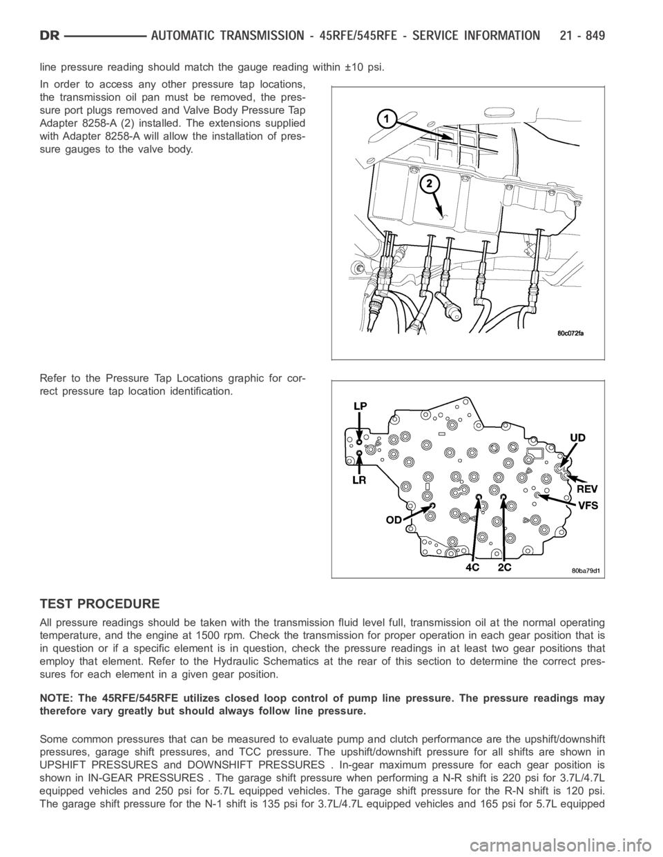
line pressure reading should match the gauge reading within ±10 psi.
In order to access any other pressure tap locations,
the transmission oil pan must be removed, the pres-
sure port plugs removed and Valve Body Pressure Tap
Adapter 8258-A (2) installed. The extensions supplied
with Adapter 8258-A will allow the installation of pres-
sure gauges to the valve body.
Refer to the Pressure Tap Locations graphic for cor-
rect pressure tap location identification.
TEST PROCEDURE
All pressure readings should be taken with the transmission fluid level full, transmission oil at the normal operating
temperature, and the engine at 1500 rpm. Check the transmission for properoperation in each gear position that is
in question or if a specific element is in question, check the pressure readings in at least two gear positions that
employ that element. Refer to the Hydraulic Schematics at the rear of this section to determine the correct pres-
sures for each element in a given gear position.
NOTE: The 45RFE/545RFE utilizes closed loop control of pump line pressure. The pressure readings may
therefore vary greatly but should always follow line pressure.
Some common pressures that can be measured to evaluate pump and clutch performance are the upshift/downshift
pressures, garage shift pressures, and TCC pressure. The upshift/downshift pressure for all shifts are shown in
UPSHIFT PRESSURES and DOWNSHIFT PRESSURES . In-gear maximum pressure foreach gear position is
shown in IN-GEAR PRESSURES . The garageshift pressure when performing a N-R shift is 220 psi for 3.7L/4.7L
equipped vehicles and 250 psi for 5.7L equipped vehicles. The garage shiftpressure for the R-N shift is 120 psi.
The garage shift pressure for the N-1 shift is 135 psi for 3.7L/4.7L equipped vehicles and 165 psi for 5.7L equipped
Page 3371 of 5267
vehicles. Torque converter lock-up pressure is 120 psi for 3.7L/4.7L equipped vehicles and 125 psi for 5.7L
equipped vehicles.
UPSHIFT PRESSURES
ENGINE 1-2 2-3 2prime-3 3-4 2prime-4 2-5 3-5 4-5
5.7L150 125 125 135 135 135 135 135
3.7L/4.7L120 120 120 120 120 120 120 130
DOWNSHIFT PRESSURES
ENGINE 5-4 5-3 5-2 4-3 4-
2prime3-2 3-
2prime2prime-1 2-1 3-1
5.7L135 135 135 135 135 135 135 135 135 135
3.7L/
4.7L120 120 120 120 120 120 120 120 120 120
IN-GEAR PRESSURES
ENGINE122prime345NEUTRALREVERSE
5.7L160 135 135 135 135 135 120 250
3.7L/4.7L135 120 120 120 120 120 120 220
AIR CHECKING TRANSMISSION CLUTCH OPERATION
Air-pressure testing can be used to check transmis-
sion clutch operation. The test can be conducted with
the transmission either in the vehicle or on the work
bench, as a final check.
Air-pressure testing requires that the oil pan and valve
body be removed from the transmission. The clutch
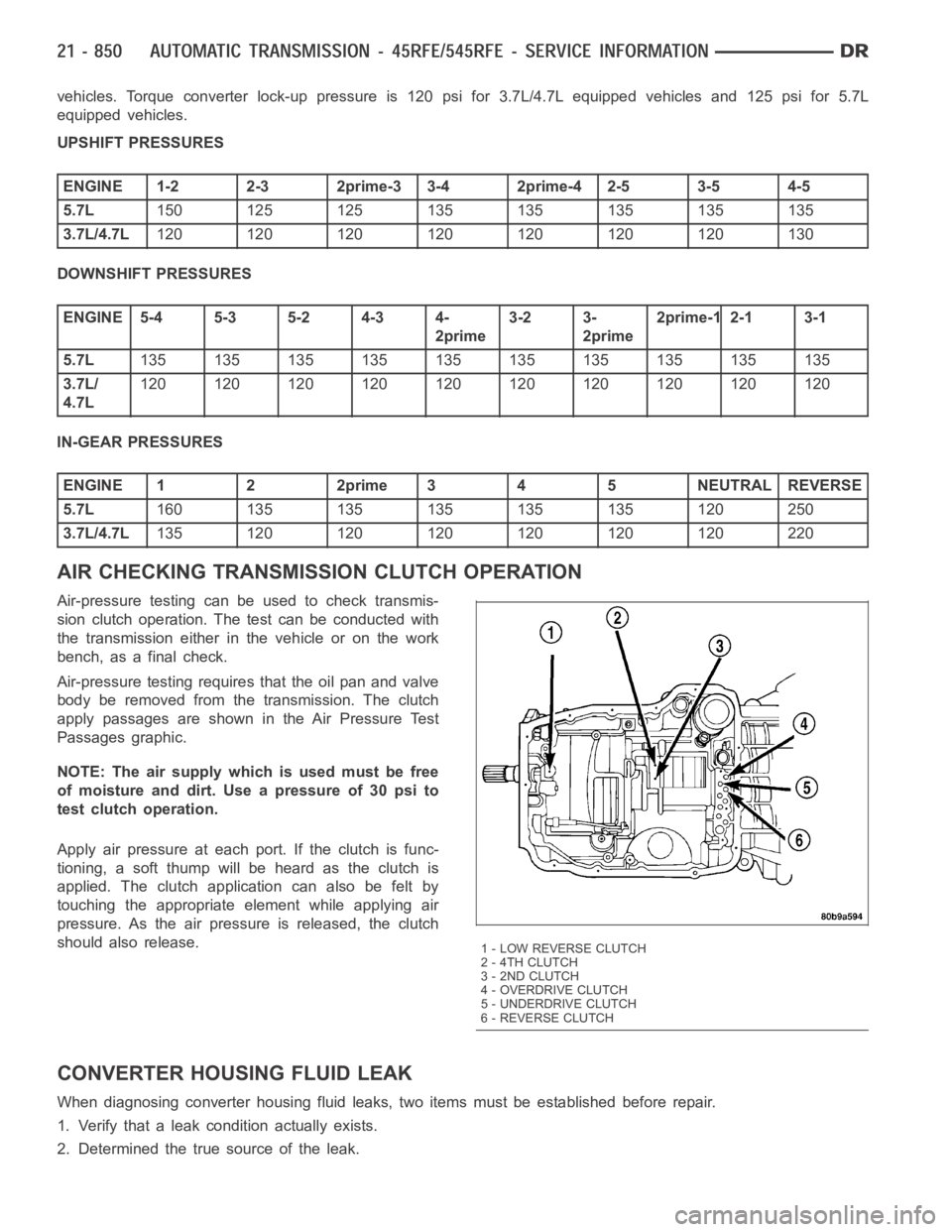
apply passages are shown in the Air Pressure Test
Passages graphic.
NOTE: The air supply which is used must be free
ofmoistureanddirt.Useapressureof30psito
test clutch operation.
Apply air pressure at each port. If the clutch is func-
tioning, a soft thump will be heard as the clutch is
applied. The clutch application can also be felt by
touching the appropriate element while applying air
pressure. As the air pressure is released, the clutch
should also release.
CONVERTER HOUSING FLUID LEAK
When diagnosing converter housing fluid leaks, two items must be established before repair.
1. Verify that a leak condition actually exists.
2. Determined the true source of the leak.
1 - LOW REVERSE CLUTCH
2 - 4TH CLUTCH
3 - 2ND CLUTCH
4-OVERDRIVECLUTCH
5 - UNDERDRIVE CLUTCH
6 - REVERSE CLUTCH
Page 3372 of 5267
Some suspected converter housing fluid leaks may not be leaks at all. They may only be the result of residual fluid
in the converter housing, or excess fluid spilled during factory fill or fill after repair. Converter housing leaks have
several potential sources. Through careful observation, a leak source can be identified before removing the trans-
mission for repair. Torque converter seal leaks tend to move along the drive hub and onto the rear of the converter.
Pump cover seal leaks tend to run down the cover and the inside surface of thebellhousing.
Some leaks, or suspected leaks, may be particularly difficult to locate. If necessary, a Mopar
approved dye should
be used to locate and confirm a leak.
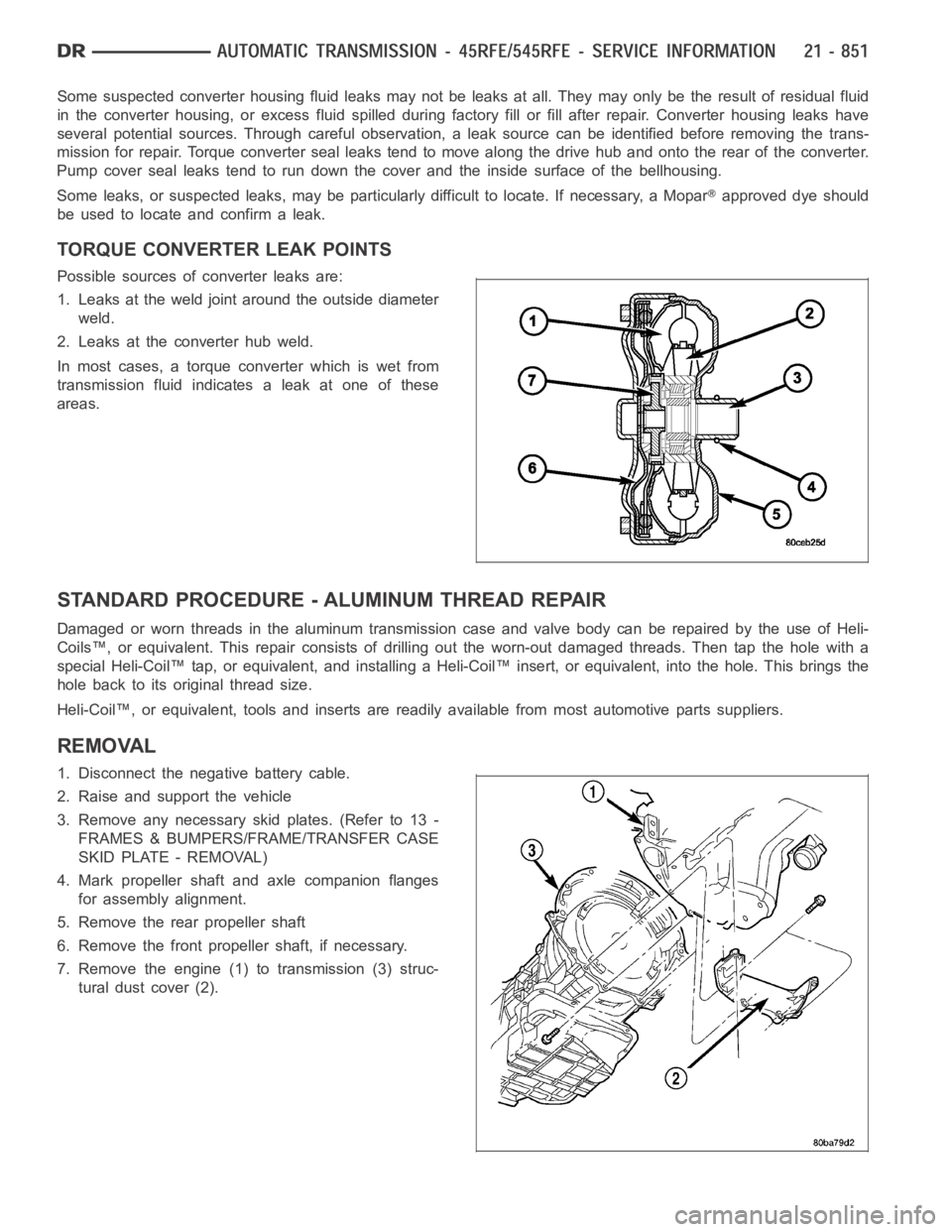
TORQUE CONVERTER LEAK POINTS
Possible sources of converter leaks are:
1. Leaks at the weld joint around the outside diameter
weld.
2. Leaks at the converter hub weld.
In most cases, a torque converter which is wet from
transmission fluid indicates a leak at one of these
areas.
STANDARD PROCEDURE - ALUMINUM THREAD REPAIR
DamagedorwornthreadsinthealuminumtransmissioncaseandvalvebodycanberepairedbytheuseofHeli-
Coils™, or equivalent. This repair consists of drilling out the worn-out damaged threads. Then tap the hole with a
special Heli-Coil™ tap, or equivalent, and installing a Heli-Coil™ insert, or equivalent, into the hole. This brings the
hole back to its original thread size.
Heli-Coil™, or equivalent, tools and inserts are readily available from most automotive parts suppliers.
REMOVAL
1. Disconnect the negative battery cable.
2. Raise and support the vehicle
3. Remove any necessary skid plates. (Refer to 13 -
FRAMES & BUMPERS/FRAME/TRANSFER CASE
SKID PLATE - REMOVAL)
4. Mark propeller shaft and axle companion flanges
for assembly alignment.
5. Remove the rear propeller shaft
6. Remove the front propeller shaft, if necessary.
7. Remove the engine (1) to transmission (3) struc-
tural dust cover (2).
Page 3376 of 5267
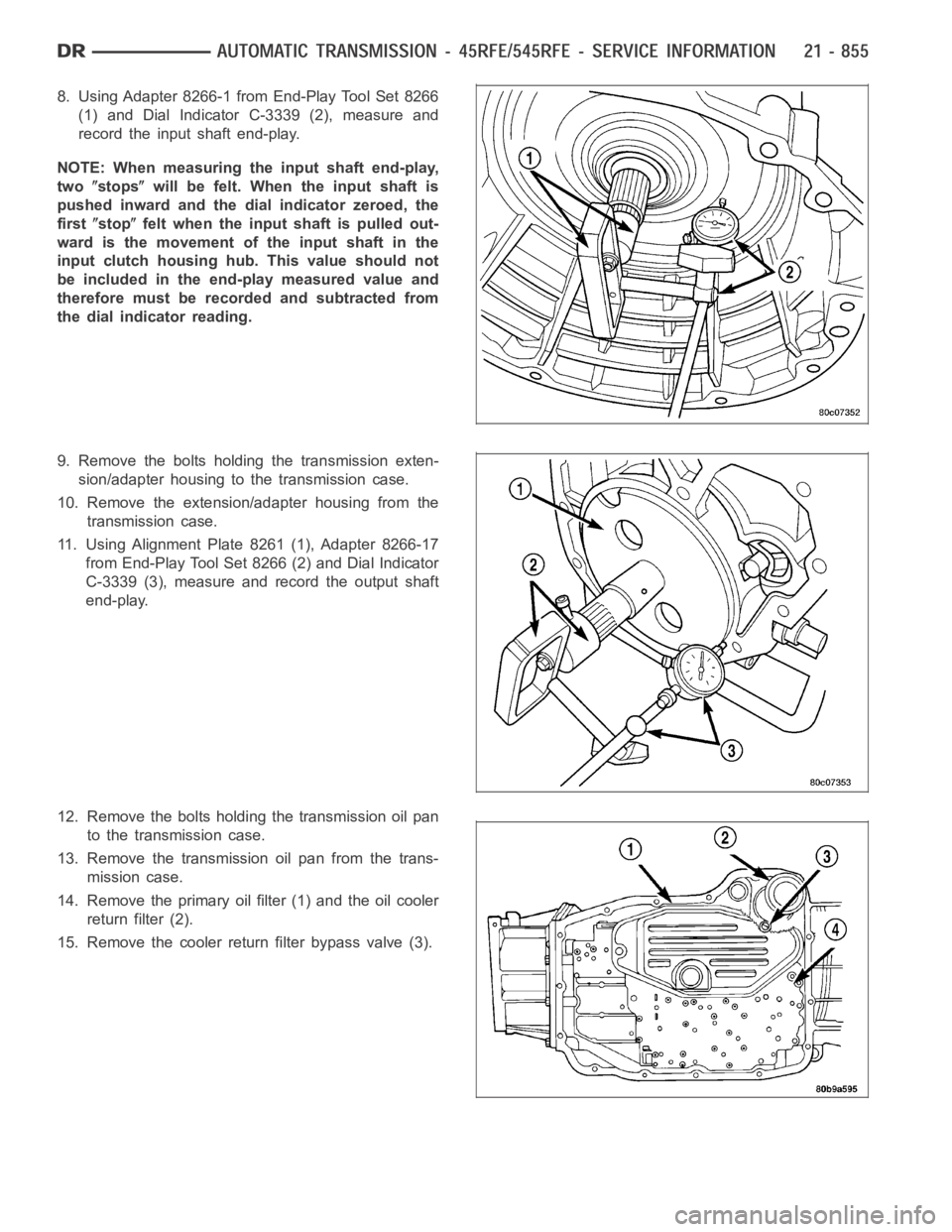
8. Using Adapter 8266-1 from End-Play Tool Set 8266
(1) and Dial Indicator C-3339 (2), measure and
record the input shaft end-play.
NOTE: When measuring the input shaft end-play,
two
stopswill be felt. When the input shaft is
pushed inward and the dial indicator zeroed, the
first
stopfelt when the input shaft is pulled out-
wardisthemovementoftheinputshaftinthe
input clutch housing hub. This value should not
be included in the end-play measured value and
therefore must be recorded and subtracted from
the dial indicator reading.
9. Remove the bolts holding the transmission exten-
sion/adapter housing to the transmission case.
10. Remove the extension/adapter housing from the
transmission case.
11. Using Alignment Plate 8261 (1), Adapter 8266-17
from End-Play Tool Set 8266 (2) and Dial Indicator
C-3339 (3), measure and record the output shaft
end-play.
12. Remove the bolts holding the transmission oil pan
to the transmission case.
13. Remove the transmission oil pan from the trans-
mission case.
14. Remove the primary oil filter (1) and the oil cooler
return filter (2).
15. Remove the cooler return filter bypass valve (3).