2006 DODGE RAM SRT-10 check engine
[x] Cancel search: check enginePage 2828 of 5267
When Monitored:
In any forward gear with engine speed above 1000 RPM, shortly after a shift and every minute thereafter.
Set Condition:
After a shift into a forward gear, with engine speed greater than 1000 RPM, the PCM momentarily turns on
element pressure to the clutch circuits that don’t have pressure to identify the correct pressure switch closes.
If the pressure switch does not close 2 times the DTC sets.
Possible Causes
LOSS OF PRIME P0944 PRESENT
(T16) TRANSMISSION CONTROL OUTPUT CIRCUIT OPEN
(T9) OD PRESSURE SWITCH SENSE CIRCUIT OPEN
(T9) OD PRESSURE SWITCH CIRCUIT SHORT TO GROUND
(T9) OD PRESSURE SWITCH SENSE CIRCUIT SHORT TO VOLTAGE
TRANSMISSION SOLENOID/PRESSURE SWITCH ASSEMBLY
INTERNAL TRANSMISSION
POWERTRAIN CONTROL MODULE
Always perform the 42RLE Pre-Diagnostic Troubleshooting procedure before proceeding. (Refer to 21 -
TRANSMISSION/TRANSAXLE/AUTOMATIC - 42RLE - STANDARD PROCEDURE)
Theory of Operation
Pressure switches are normally off or open (no pressure applied) and read high (+12 volts). When an element is
applied, the corresponding pressure switch closes to ground (0 volts) or turns on. The controller tests the OD and
2/4 pressure switches when they are off (when the corresponding friction element is not applied) by briefly applying
the OD and 2/4 elements which will cause the corresponding pressure switchto close. The test verifies that the
switches are operational and that the switch will close when the corresponding element is applied. If a switch fails
to respond, it is re-tested. The MIL illuminates and the transmission system defaults to Limp-in mode.
Diagnostic Test
1.CHECKING FOR LOSS OF PRIME DTC
With the scan tool, check for other Transmission DTCs.
Is the DTC P0944 present also?
Ye s>>
Refer to the Transmission category and perform the appropriate diagnostic procedure.
No>>
Go To 2
2.CHECK FOR RELATED TRANSMISSION DTCS
With the scan tool, read Transmission DTCs.
Are any of the DTCs P0732, P0734 and/or P0846 present also?
Ye s>>
Replace the Transmission Solenoid/Pressure Switch Assembly per the Service Information.
Perform 42RLE TRANSMISSION VERIFICATION TEST - VER 1. (Refer to 21 - TRANSMISSION/
TRANSAXLE/AUTOMATIC - 42RLE - STANDARD PROCEDURE)
No>>
Go To 3
Page 2829 of 5267
3.CHECK TO SEE IF DTC P0870 IS CURRENT
With the scan tool, view DTCs.
Is the status Active for this DTC or is the STARTS SINCE SET counter 2 or less?
Ye s>>
Go To 4
No>>
Go To 9
4.PCM AND WIRING
Turn the ignition off to the lock position.
Remove the Ignition Switch Feed fuse from the TIPM.
CAUTION: Removal of the Ignition Switch Feed fuse from the TIPM will prevent the vehicle from being
startedingear.
WARNING: The Ignition Switch Feed fuse must be removed from the TIPM. Failure to do so can result in
personal injury or death.
Install the Transmission Simulator,Miller tool #8333 and the ElectronicTransmission Adapter kit.
Ignition on, engine not running.
With the Transmission Simulator, turn the Pressure Switch selector switchtoOD.
With the scan tool, monitor the UD Pressure Switch state while pressing thePressure Switch Test button on the
Transmission Simulator.
Wiggle the wires leading to the PCM while pressing and holding the PressureSwitch Test button.
Did the OD Pressure Switch state change to closed and remain closed while wiggling the wires?
Ye s>>
Disassemble and inspect the Valve Body per the Service Information and repair or replace as neces-
sary. If no problems are found in the Valve Body, replace the Transmission Solenoid/Pressure Switch
Assembly.
Perform 42RLE TRANSMISSION VERIFICATION TEST - VER 1. (Refer to 21 - TRANSMISSION/
TRANSAXLE/AUTOMATIC - 42RLE - STANDARD PROCEDURE)
No>>
Go To 5
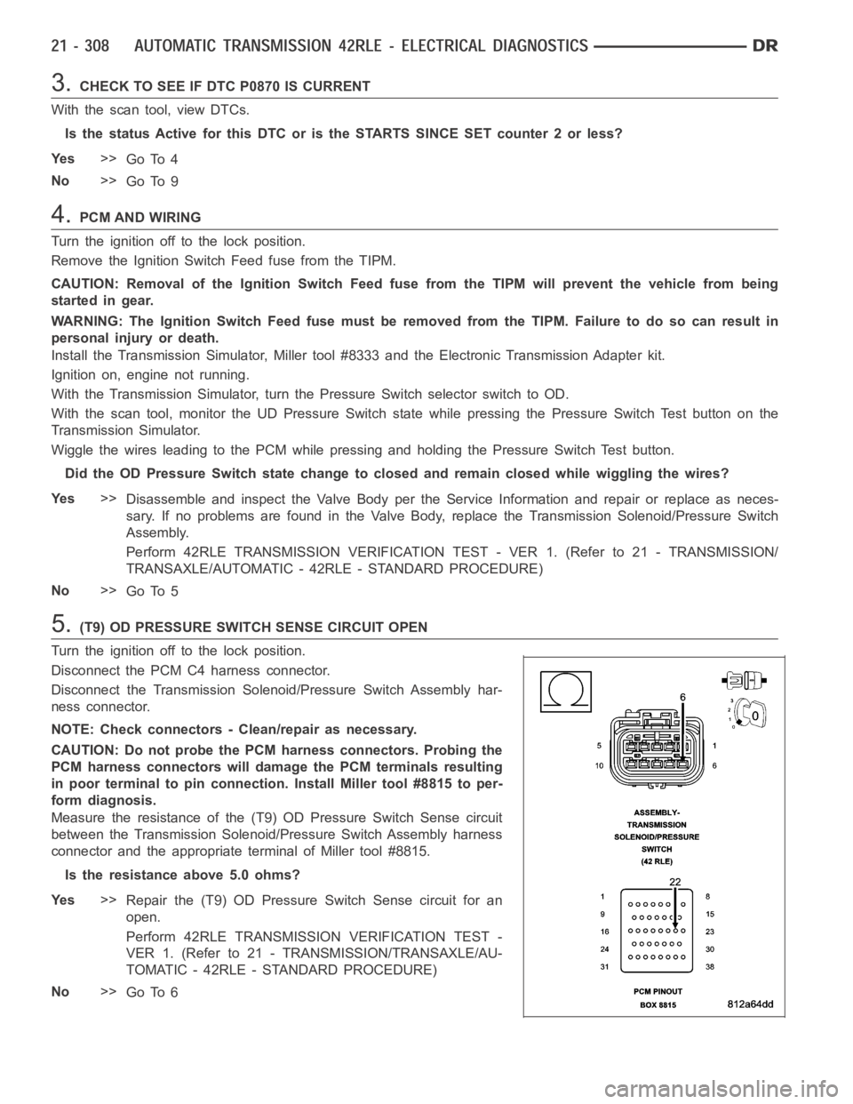
5.(T9) OD PRESSURE SWITCH SENSE CIRCUIT OPEN
Turn the ignition off to the lock position.
Disconnect the PCM C4 harness connector.
Disconnect the Transmission Solenoid/Pressure Switch Assembly har-
ness connector.
NOTE: Check connectors - Clean/repair as necessary.
CAUTION: Do not probe the PCM harness connectors. Probing the
PCM harness connectors will damage the PCM terminals resulting
in poor terminal to pin connection. Install Miller tool #8815 to per-
form diagnosis.
Measure the resistance of the (T9) OD Pressure Switch Sense circuit
between the Transmission Solenoid/Pressure Switch Assembly harness
connector and the appropriate terminal of Miller tool #8815.
Is the resistance above 5.0 ohms?
Ye s>>
Repair the (T9) OD Pressure Switch Sense circuit for an
open.
Perform 42RLE TRANSMISSION VERIFICATION TEST -
VER 1. (Refer to 21 - TRANSMISSION/TRANSAXLE/AU-
TOMATIC - 42RLE - STANDARD PROCEDURE)
No>>
Go To 6
Page 2833 of 5267
When Monitored:
Whenever the engine is running.
Set Condition:
The DTC is set if one of the pressure switches are open or closed at the wrong time in a given gear. If the
problem is identified for 3 successive key starts, the transmission will go into Limp-in mode and the MIL will
turn on after 10 seconds of vehicle operation.
Possible Causes
RELATED TIPM TCM POWER INPUT DTCS PRESENT
LOSS OF PRIME DTC PRESENT
(T9) OD PRESSURE SWITCH SENSE CIRCUIT OPEN
(T9) OD PRESSURE SWITCH SENSE CIRCUIT SHORT TO GROUND
(T9) OD PRESSURE SWITCH SENSE CIRCUIT SHORT TO VOLTAGE
TRANSMISSION SOLENOID/PRESSURE SWITCH ASSEMBLY
POWERTRAIN CONTROL MODULE
Always perform the 42RLE Pre-Diagnostic Troubleshooting procedure before proceeding. (Refer to 21 -
TRANSMISSION/TRANSAXLE/AUTOMATIC - 42RLE - STANDARD PROCEDURE)
Theory of Operation
The Transmission system uses three pressure switches to monitor the fluidpressure in the LR, 2/4, and OD ele-
ments. The pressure switches are continuously monitored for the correct states in each gear. Normal operation will
be experienced if no other codes are present. Transmission Control Systemwill ignore the code. Limp-in condition
will only occur if DTC P0871 is present with a DTC P0706.
PRESSURE SWITCH STATES
GEAR L/R 2/4 OD
ROPOPOP
P/N CL OP OP
1st CL OP OP
2nd OP CL OP
DOPOPCL
OD OP CL CL
OP = OPEN
CL = CLOSED
Diagnostic Test
1.CHECK FOR TIPM TCM POWER INPUT DTCS
With the scan tool under TIPM, check for TCM Power Input DTCs.
Are there any TIPM TCM Power Input DTCs present?
Ye s>>
Refer to the Transmission category and perform the appropriate diagnostic procedure.
No>>
Go To 2
Page 2834 of 5267
2.CHECK FOR LOSS OF PRIME DTC
With the scan tool, check for other Transmission DTCs.
Is the DTC P0944 present also?
Ye s>>
Refer to the Transmission category and perform the appropriate diagnostic procedure.
No>>
Go To 3
3.CHECK TO SEE IF P0841 IS CURRENT
With the scan tool, view DTCs.
Is the status Active for this DTC or is the STARTS SINCE SET counter 2 or less?
Ye s>>
Go To 4
No>>
Go To 8
4.PCM AND WIRING
Turn the ignition off to the lock position.
Remove the Ignition Switch Feed fuse from the TIPM.
CAUTION: Removal of the Ignition Switch Feed fuse from the TIPM will prevent the vehicle from being
startedingear.
WARNING: The Ignition Switch Feed fuse must be removed from the TIPM. Failure to do so can result in
personal injury or death.
Install the Transmission Simulator,Miller tool #8333 and the ElectronicTransmission Adapter kit.
Ignition on, engine not running.
With the Transmission Simulator, turn the Pressure Switch selector to OD.
With the scan tool , monitor the OD Pressure Switch state while pressing thePressure Switch Test button on the
Transmission Simulator.
Did the OD Pressure Switch state change?
Ye s>>
Replace the Transmission Solenoid/Pressure Switch Assembly per the Service Information.
Perform 42RLE TRANSMISSION VERIFICATION TEST - VER 1. (Refer to 21 - TRANSMISSION/
TRANSAXLE/AUTOMATIC - 42RLE - STANDARD PROCEDURE)
No>>
Go To 5
Page 2836 of 5267
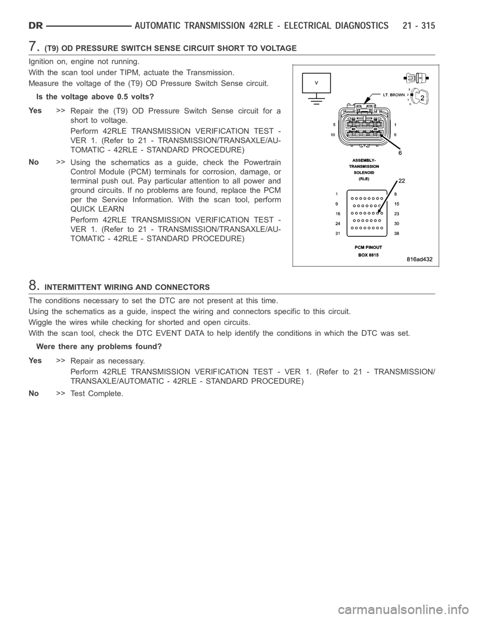
7.(T9) OD PRESSURE SWITCH SENSE CIRCUIT SHORT TO VOLTAGE
Ignition on, engine not running.
With the scan tool under TIPM, actuate the Transmission.
Measure the voltage of the (T9) OD Pressure Switch Sense circuit.
Is the voltage above 0.5 volts?
Ye s>>
Repair the (T9) OD Pressure Switch Sense circuit for a
short to voltage.
Perform 42RLE TRANSMISSION VERIFICATION TEST -
VER 1. (Refer to 21 - TRANSMISSION/TRANSAXLE/AU-
TOMATIC - 42RLE - STANDARD PROCEDURE)
No>>
Using the schematics as a guide, check the Powertrain
Control Module (PCM) terminals for corrosion, damage, or
terminal push out. Pay particular attention to all power and
ground circuits. If no problems are found, replace the PCM
per the Service Information.With the scan tool, perform
QUICK LEARN
Perform 42RLE TRANSMISSION VERIFICATION TEST -
VER 1. (Refer to 21 - TRANSMISSION/TRANSAXLE/AU-
TOMATIC - 42RLE - STANDARD PROCEDURE)
8.INTERMITTENT WIRING AND CONNECTORS
The conditions necessary to set the DTC are not present at this time.
Using the schematics as a guide, inspect the wiring and connectors specifictothiscircuit.
Wiggle the wires while checking for shorted and open circuits.
With the scan tool, check the DTC EVENT DATA to help identify the conditionsin which the DTC was set.
Were there any problems found?
Ye s>>
Repair as necessary.
Perform 42RLE TRANSMISSION VERIFICATION TEST - VER 1. (Refer to 21 - TRANSMISSION/
TRANSAXLE/AUTOMATIC - 42RLE - STANDARD PROCEDURE)
No>>
Te s t C o m p l e t e .
Page 2838 of 5267
When Monitored:
When the ignition is turned from
OFFposition toRUNposition and/or the ignition is turned fromSTART
position toRUNposition.
Set Condition:
This DTC is set when there is less than 3.0 volts present at the transmissioncontrol output circuits located in
the Powertrain Control Module (PCM) when the Transmission Control Systemrequest the power up of those
circuits.Note: Due to the integration of the Transmission Control Module and the Powertrain Control
Module, both systems have their own power and ground circuits..
Possible Causes
RELATED TIPM DTCS
(T515) TRANSMISSION CONTROL CIRCUIT SHORT TO GROUND
(T515) TRANSMISSION CONTROL CIRCUIT OPEN
POWERTRAIN CONTROL MODULE
Always perform the 42RLE Pre-Diagnostic Troubleshooting procedure before proceeding. (Refer to 21 -
TRANSMISSION/TRANSAXLE/AUTOMATIC - 42RLE - STANDARD PROCEDURE)
Theory of Operation
The Transmission Control Output circuit is used to supply power to the Transmission Solenoid/TRS Assembly and to
the PCM when in normal operating mode. The purpose of the Transmission Output circuit is to allow the Transmis-
sion Control System to turn off the power to the Transmission Solenoid/TRSAssembly in event that the transmission
should need to be placed into “limp-in” mode due to a DTC.
After a PCM reset, (ignition switch turned to the run position, or after cranking the engine) the Transmission Control
System verifies that the Transmission Output circuit is open by checking for voltage on the Transmission Output
circuits before the Transmission Control System request for the circuit to be powered up. The request is sent by a
direct circuit control from the PCM tothe TIPM. If the Transmission Control System detects less that 3.0 volts when
the output is commanded on, the DTC will set.Note: Inadequate Transmission Control Output voltage can also
cause DTCs P0846, P0869, or P0871 to set. Repairing the P0882 fault should also eliminate the related
DTCs.
Diagnostic Test
1.CHECK IF THE DTC P0882 IS CURRENT
With the scan tool, Check the STARTS SINCE SET counter for P0882.
NOTE: This counter only applies to the last DTC set.
Is the STARTS SINCE SET counter equal to 0?
Ye s>>
Go To 2
No>>
Go To 5
2.CHECK FOR TIPM RELATED DTCS
With the scan tool, check TIPM DTCs.
Are there any TIPM TCM Power Control circuit DTCs present?
Ye s>>
Refer to the Transmission category and perform the appropriate symptom.
No>>
Go To 3
Page 2842 of 5267
When Monitored:
When the ignition is turned from
OFFposition toRUNposition and/or the ignition is turned fromSTART
position toRUNposition.
Set Condition:
This DTC is set if the Powertrain Control Module senses greater than 3.0 volts on the Transmission Control
Relay Output circuits prior to a request from the PCM to TIPM to energize theTransmission Output circuits.
Possible Causes
TIPM DTCS PRESENT
(T515) TRANSMISSION CONTROL CIRCUIT SHORT TO VOLTAGE
(T16) TRANSMISSION CONTROL OUTPUT CIRCUIT SHORT VOLTAGE
TRANSMISSION SOLENOID/TRS ASSEMBLY
POWERTRAIN CONTROL MODULE
Always perform the 42RLE Pre-Diagnostic Troubleshooting procedure before proceeding. (Refer to 21 -
TRANSMISSION/TRANSAXLE/AUTOMATIC - 42RLE - STANDARD PROCEDURE)
Theory of Operation
The Transmission Control Output circuit is used to supply power to the Transmission Solenoid/TRS Assembly and to
the PCM when in normal operating mode. The purpose of the Transmission Output circuit is to allow the Transmis-
sion Control System to turn off the power to the Transmission Solenoid/TRSAssembly in event that the transmission
should need to be placed into “limp-in” mode due to a DTC.
After a PCM reset, (ignition switch turned to the run position, or after cranking the engine) the Transmission Control
System verifies that the Transmission Output circuit is open by checking for voltage on the Transmission Output
circuits before the Transmission Control System request for the circuit to be powered up. The request is sent by a
direct circuit control from the PCM tothe TIPM. If voltage is detected on the Transmission Output circuits before the
request is sent, the DTC will set.
Diagnostic Test
1.CHECK FOR TCM TIPM DTCS
With the scan tool under TIPM, check for TCM Power Control circuit DTCs.
Are there any TIPM TCM Power Control circuit DTCS present?
Ye s>>
Refer to the Transmission category and perform the appropriate symptom.
No>>
Go To 2
2.CHECK TO SEE IF DTC P0883 IS CURRENT
With the scan tool, check the STARTS SINCE SET counter.
NOTE: This counter only applies to the last DTC set.
Is the STARTS SINCE SET counter set to 0?
Ye s>>
Go To 3
No>>
Go To 6
Page 2843 of 5267
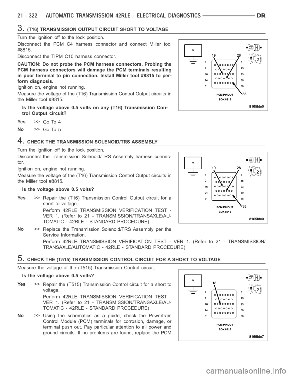
3.(T16) TRANSMISSION OUTPUT CIRCUIT SHORT TO VOLTAGE
Turn the ignition off to the lock position.
Disconnect the PCM C4 harness connector and connect Miller tool
#8815.
Disconnect the TIPM C10 harness connector.
CAUTION: Do not probe the PCM harness connectors. Probing the
PCM harness connectors will damage the PCM terminals resulting
in poor terminal to pin connection. Install Miller tool #8815 to per-
form diagnosis.
Ignition on, engine not running.
Measure the voltage of the (T16) Transmission Control Output circuits in
the Miller tool #8815.
Is the voltage above 0.5 volts on any (T16) Transmission Con-
trol Output circuit?
Ye s>>
Go To 4
No>>
Go To 5
4.CHECK THE TRANSMISSION SOLENOID/TRS ASSEMBLY
Turn the ignition off to the lock position.
Disconnect the Transmission Solenoid/TRS Assembly harness connec-
tor.
Ignition on, engine not running.
Measure the voltage of the (T16) Transmission Control Output circuits in
the Miller tool #8815.
Is the voltage above 0.5 volts?
Ye s>>
Repair the (T16) Transmission Control Output circuit for a
short to voltage.
Perform 42RLE TRANSMISSION VERIFICATION TEST -
VER 1. (Refer to 21 - TRANSMISSION/TRANSAXLE/AU-
TOMATIC - 42RLE - STANDARD PROCEDURE)
No>>
Replace the Transmission Solenoid/TRS Assembly per the
Service Information.
Perform 42RLE TRANSMISSION VERIFICATION TEST - VER 1. (Refer to 21 - TRANSMISSION/
TRANSAXLE/AUTOMATIC - 42RLE - STANDARD PROCEDURE)
5.CHECK THE (T515) TRANSMISSION CONTROL CIRCUIT FOR A SHORT TO VOLTAGE
Measure the voltage of the (T515) Transmission Control circuit.
Is the voltage above 0.5 volts?
Ye s>>
Repair the (T515) Transmission Control circuit for a short to
voltage.
Perform 42RLE TRANSMISSION VERIFICATION TEST -
VER 1. (Refer to 21 - TRANSMISSION/TRANSAXLE/AU-
TOMATIC - 42RLE - STANDARD PROCEDURE)
No>>
Using the schematics as a guide, check the Powertrain
Control Module (PCM) terminals for corrosion, damage, or
terminal push out. Pay particular attention to all power and
ground circuits. If no problems are found, replace the PCM