2006 DODGE RAM SRT-10 check engine
[x] Cancel search: check enginePage 2868 of 5267
When Monitored:
With the ignition on. Battery voltage greater than 10 volts.
Set Condition:
A shorted condition is detected in the Transmission Control Output circuit.
Possible Causes
(T16) TRANSMISSION CONTROL OUTPUT CIRCUIT SHORT TO GROUND
(T16) TRANSMISSION CONTROL OUTPUT CIRCUIT FOR AN OPEN
TOTALLY INTEGRATED POWER MODULE (TIPM)
Diagnostic Test
1.CHECK IF THE DTC IS ACTIVE
Ignition on, engine not running.
With the scan tool, check TIPM DTCs.
Is the status Active for this DTC?
Ye s>>
Go to 2
No>>
Go to 5
2.CHECK THE (T16) TRANSMISSION CONTROL OUTPUT CIRCUIT SHORT TO GROUND
Turn the ignition off
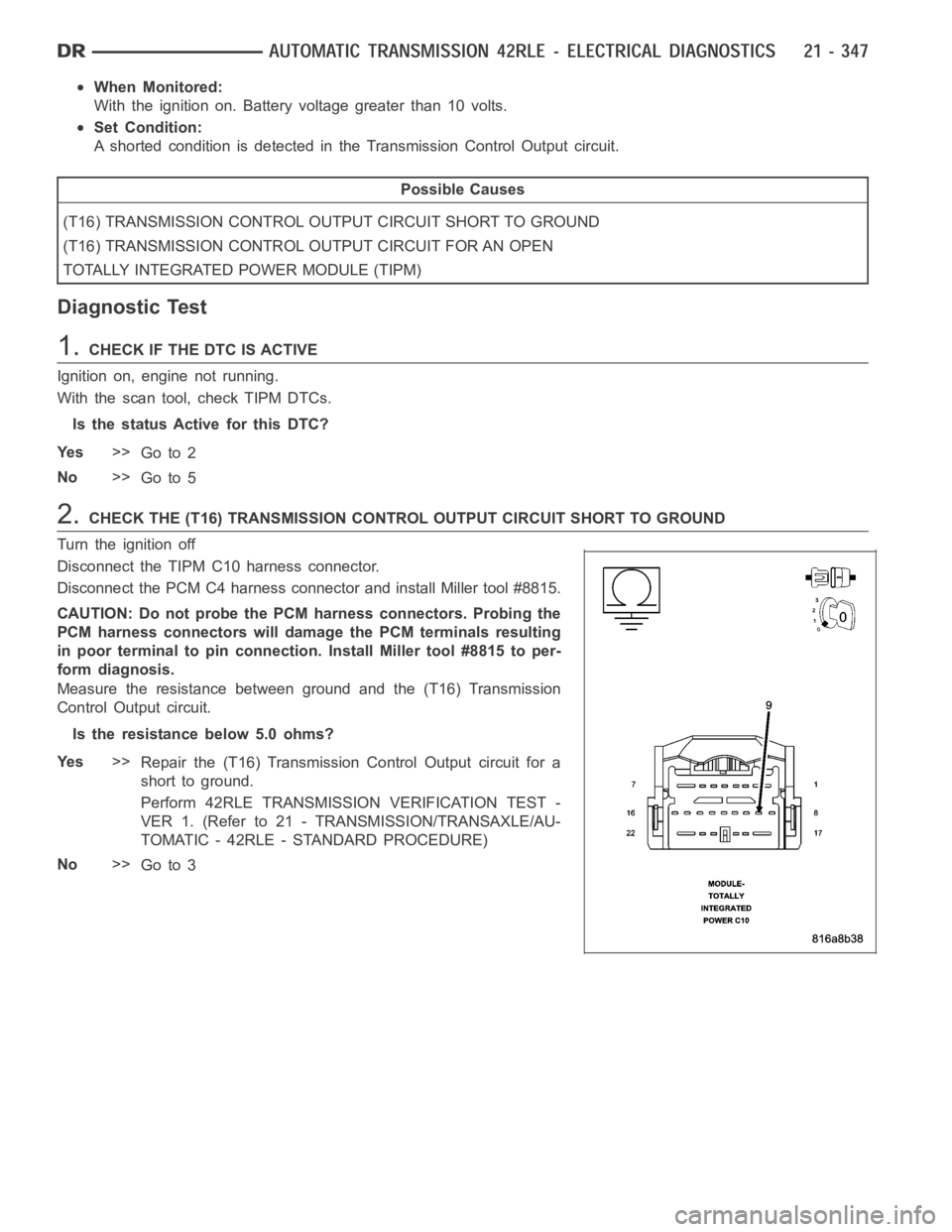
Disconnect the TIPM C10 harness connector.
Disconnect the PCM C4 harness connector and install Miller tool #8815.
CAUTION: Do not probe the PCM harness connectors. Probing the
PCM harness connectors will damage the PCM terminals resulting
in poor terminal to pin connection. Install Miller tool #8815 to per-
form diagnosis.
Measure the resistance between ground and the (T16) Transmission
Control Output circuit.
Is the resistance below 5.0 ohms?
Ye s>>
Repair the (T16) Transmission Control Output circuit for a
short to ground.
Perform 42RLE TRANSMISSION VERIFICATION TEST -
VER 1. (Refer to 21 - TRANSMISSION/TRANSAXLE/AU-
TOMATIC - 42RLE - STANDARD PROCEDURE)
No>>
Go to 3
Page 2869 of 5267
3.CHECK THE (T16) TRANSMISSION CONTROL OUTPUT CIRCUIT FOR AN OPEN
Turn the ignition off to the lock position.
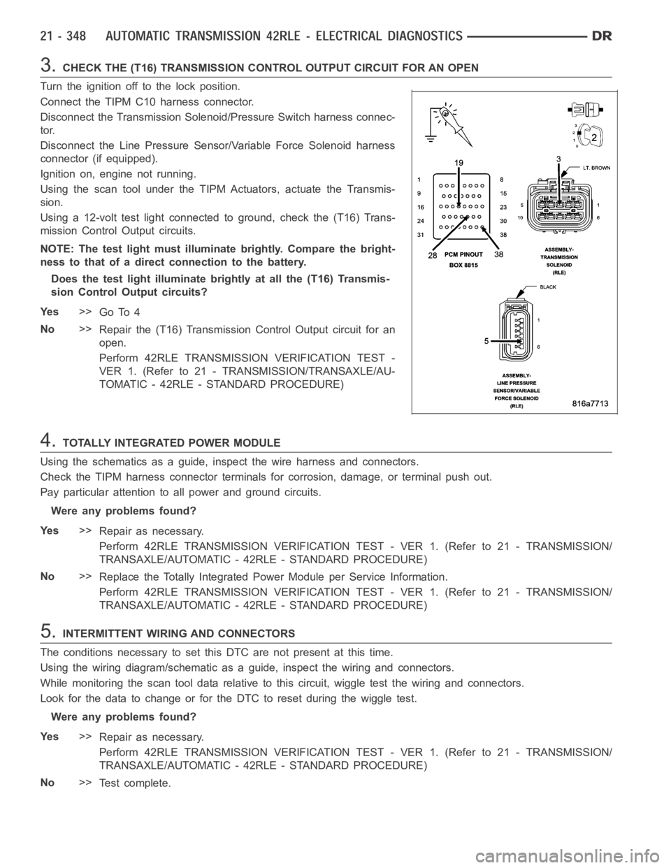
Connect the TIPM C10 harness connector.
Disconnect the Transmission Solenoid/Pressure Switch harness connec-
tor.
Disconnect the Line Pressure Sensor/Variable Force Solenoid harness
connector (if equipped).
Ignition on, engine not running.
Using the scan tool under the TIPM Actuators, actuate the Transmis-
sion.
Using a 12-volt test light connected to ground, check the (T16) Trans-
mission Control Output circuits.
NOTE: The test light must illuminate brightly. Compare the bright-
ness to that of a direct connection to the battery.
Does the test light illuminate brightly at all the (T16) Transmis-
sion Control Output circuits?
Ye s>>
Go To 4
No>>
Repair the (T16) Transmission Control Output circuit for an
open.
Perform 42RLE TRANSMISSION VERIFICATION TEST -
VER 1. (Refer to 21 - TRANSMISSION/TRANSAXLE/AU-
TOMATIC - 42RLE - STANDARD PROCEDURE)
4.TOTALLY INTEGRATED POWER MODULE
Using the schematics as a guide, inspect the wire harness and connectors.
Check the TIPM harness connector terminals for corrosion, damage, or terminal push out.
Pay particular attention to all power and ground circuits.
Were any problems found?
Ye s>>
Repair as necessary.
Perform 42RLE TRANSMISSION VERIFICATION TEST - VER 1. (Refer to 21 - TRANSMISSION/
TRANSAXLE/AUTOMATIC - 42RLE - STANDARD PROCEDURE)
No>>
Replace the Totally Integrated Power Module per Service Information.
Perform 42RLE TRANSMISSION VERIFICATION TEST - VER 1. (Refer to 21 - TRANSMISSION/
TRANSAXLE/AUTOMATIC - 42RLE - STANDARD PROCEDURE)
5.INTERMITTENT WIRING AND CONNECTORS
The conditions necessary to set this DTC are not present at this time.
Using the wiring diagram/schematic as a guide, inspect the wiring and connectors.
While monitoring the scan tool data relative to this circuit, wiggle test the wiring and connectors.
Look for the data to change or for the DTC to reset during the wiggle test.
Were any problems found?
Ye s>>
Repair as necessary.
Perform 42RLE TRANSMISSION VERIFICATION TEST - VER 1. (Refer to 21 - TRANSMISSION/
TRANSAXLE/AUTOMATIC - 42RLE - STANDARD PROCEDURE)
No>>
Te s t c o m p l e t e .
Page 2871 of 5267
When Monitored:
With the ignition on. Battery voltage greater than 10 volts.
Set Condition:
A shorted condition is detected in the TIPM TCM Power control circuit.
Possible Causes
(T16) TRANSMISSION CONTROL OUTPUT CIRCUIT SHORT TO VOLTAGE
TOTALLY INTEGRATED POWER MODULE (TIPM)
Diagnostic Test
1.CHECK IF THE DTC IS ACTIVE
Ignition on, engine not running.
With the scan tool, read TIPM DTCs.
Is the status Active for this DTC?
Ye s>>
Go to 2
No>>
Go to 4
2.(T16) TRANSMISSION CONTROL OUTPUT CIRCUIT SHORT TO VOLTAGE
Turn the ignition off
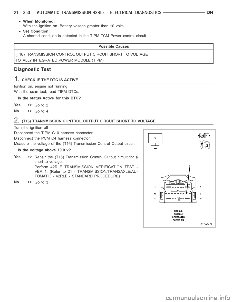
Disconnect the TIPM C10 harness connector.
Disconnect the PCM C4 harness connector.
Measure the voltage of the (T16) Transmission Control Output circuit.
Is the voltage above 10.0 v?
Ye s>>
Repair the (T16) Transmission Control Output circuit for a
short to voltage.
Perform 42RLE TRANSMISSION VERIFICATION TEST -
VER 1. (Refer to 21 - TRANSMISSION/TRANSAXLE/AU-
TOMATIC - 42RLE - STANDARD PROCEDURE)
No>>
Go to 3
Page 2874 of 5267
When Monitored:
With the ignition on. Battery voltage greater than 10 volts.
Set Condition:
An open condition of the Transmission Control Output circuit is detected by the Totally Integrated Power Mod-
ule (TIPM).
Possible Causes
(T16) TRANSMISSION CONTROL OUTPUT CIRCUIT OPEN
TOTALLY INTEGRATED POWER MODULE (TIPM)
Diagnostic Test
1.CHECK IF THE DTC IS ACTIVE
Ignition on, engine not running.
With the scan tool, select View DTCs.
Is the status Active for this DTC?
Ye s>>
Go to 2
No>>
Go to 4
2.CHECK THE (T16) TRANSMISSION CONTROL OUTPUT CIRCUIT FOR AN OPEN
Turn the ignition off to the lock position.
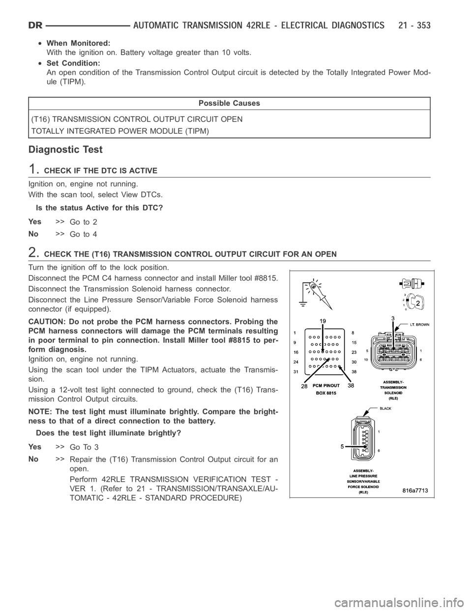
Disconnect the PCM C4 harness connector and install Miller tool #8815.
Disconnect the Transmission Solenoid harness connector.
Disconnect the Line Pressure Sensor/Variable Force Solenoid harness
connector (if equipped).
CAUTION: Do not probe the PCM harness connectors. Probing the
PCM harness connectors will damage the PCM terminals resulting
in poor terminal to pin connection. Install Miller tool #8815 to per-
form diagnosis.
Ignition on, engine not running.
Using the scan tool under the TIPM Actuators, actuate the Transmis-
sion.
Using a 12-volt test light connected to ground, check the (T16) Trans-
mission Control Output circuits.
NOTE: The test light must illuminate brightly. Compare the bright-
ness to that of a direct connection to the battery.
Does the test light illuminate brightly?
Ye s>>
Go To 3
No>>
Repair the (T16) Transmission Control Output circuit for an
open.
Perform 42RLE TRANSMISSION VERIFICATION TEST -
VER 1. (Refer to 21 - TRANSMISSION/TRANSAXLE/AU-
TOMATIC - 42RLE - STANDARD PROCEDURE)
Page 2877 of 5267
When Monitored:
With the ignition on. Battery voltage greater than 10 volts.
Set Condition:
An overcurrent condition is detected in the TCM Power Control circuit. OneTrip Fault. Three good trips to turn
off the MIL.
Possible Causes
LINE PRESSURE SENSOR VARIABLE FORCE SOLENOID
SOLENOID/PRESSURE SWITCH ASSEMBLY
POWERTRAIN CONTROL MODULE (PCM)
TOTALLY INTEGRATED POWER MODULE (TIPM)
Diagnostic Test
1.CHECK IF THE DTC IS ACTIVE
Ignition on, engine not running.
With a scan tool, read TIPM DTCs.
Is the DTC active at this time?
Ye s>>
Go To 2
No>>
Go To 5
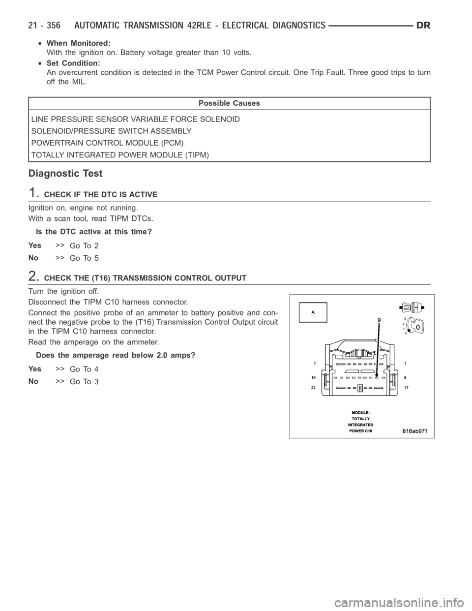
2.CHECK THE (T16) TRANSMISSION CONTROL OUTPUT
Turn the ignition off.
Disconnect the TIPM C10 harness connector.
Connect the positive probe of an ammeter to battery positive and con-
nect the negative probe to the (T16) Transmission Control Output circuit
in the TIPM C10 harness connector.
Read the amperage on the ammeter.
Does the amperage read below 2.0 amps?
Ye s>>
Go To 4
No>>
Go To 3
Page 2883 of 5267
P1713-RESTRICTED MANUAL VALVE IN T2 RANGE
For a complete wiring diagramRefer to Section 8W
When Monitored:
Ignition on, engine running with the gear shift selector in a valid forwardgear.
Set Condition:
This DTC sets whenever Transmission control system detects the manual valve is in the T2 range when it
should be in OD. This is mainly an informational DTC.
Possible Causes
RELATED TRANSMISSION DTC’S PRESENT
CUSTOMER DRIVING HABITS
MIS-ADJUSTED SHIFTER CABLE
Always perform the Pre-Diagnostic Troubleshooting procedure before proceeding. (Refer to 21 - TRANSMIS-
SION/TRANSAXLE/AUTOMATIC - 42RLE - STANDARD PROCEDURE)
Diagnostic Test
1.DETERMINING IF RELATED DTC’S ARE PRESENT
With the scan tool, check for other transmission DTC’s
Are there any speed sensor or gear ratio DTCs present?
Ye s>>
Refer to the Transmission category and perform the appropriate symptom.
No>>
Go To 2
2.CHECK THE GEAR SHIFT CABLE FOR PROPER ADJUSTMENT
Check the Gear shift cable adjustment per the Service Information.
Also check the cable for possible binding or improperly routed.
Is the Gear shift cable properly adjusted and not binding or improperly routed?
Ye s>>
Go To 3
No>>
Adjust the Shifter Assembly per the Service Information.
Perform 42RLE TRANSMISSION VERIFICATION TEST - VER 1. (Refer to 21 - TRANSMISSION/
TRANSAXLE/AUTOMATIC - 42RLE - STANDARD PROCEDURE)
3.CHECK CUSTOMER DRIVING HABIT
This DTC can be set if the customer does not move the shift lever completely into the OD position (in between
gears) causing the manual valve to be in the T2 position.
When this occurs, the feed port to the clutch is restricted, the transmission will declare neutral, and this DTC will
set.
This DTC can also be set by simply bumping the shift lever toward neutral while accelerating.
With the scan tool, check the DTC EVENT DATA to help identify the conditionsin which the DTC was set.
If there are no possible causes remaining, view repair.
Repair
This DTC can be set by the shift lever inthe wrong position or not completelyin the OD position. Make
sure the customer is properly informed.
Perform 42RLE TRANSMISSION VERIFICATION TEST - VER 1. (Refer to 21 - TRANSMISSION/
TRANSAXLE/AUTOMATIC - 42RLE - STANDARD PROCEDURE)
Page 2887 of 5267
3.PCM AND WIRING
Turn the ignition off to the lock position.
Remove the Ignition Switch Feed fuse from the TIPM.
CAUTION: Removal of the Ignition Switch Feed fuse from the TIPM will prevent the vehicle from being
startedingear.
WARNING: The Ignition Switch Feed fuse must be removed from the TIPM. Failure to do so can result in
personal injury or death.
Install the Transmission Simulator,Miller tool #8333 and the ElectronicTransmission Adapter kit.
Ignition on, engine not running.
With the Transmission Simulator, turn the Pressure Switch selector switchtoL/R.
With the scan tool, monitor the L/R Pressure Switch State while pressing the Pressure Switch Test button.
Did the Pressure Switch state change from open to closed when the test button was pressed?
Ye s>>
Repair internal transmission as necessary per the Service Information. Inspect the Solenoid Switch
Valve per the Service Information and repair or replace as necessary. If noproblems are found, replace
the Transmission Solenoid/Pressure Switch Assembly.
Perform 42RLE TRANSMISSION VERIFICATION TEST - VER 1. (Refer to 21 - TRANSMISSION/
TRANSAXLE/AUTOMATIC - 42RLE - STANDARD PROCEDURE)
No>>
Go To 4
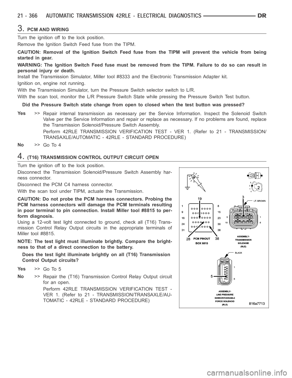
4.(T16) TRANSMISSION CONTROL OUTPUT CIRCUIT OPEN
Turn the ignition off to the lock position.
Disconnect the Transmission Solenoid/Pressure Switch Assembly har-
ness connector.
Disconnect the PCM C4 harness connector.
With the scan tool under TIPM, actuate the Transmission.
CAUTION: Do not probe the PCM harness connectors. Probing the
PCM harness connectors will damage the PCM terminals resulting
in poor terminal to pin connection. Install Miller tool #8815 to per-
form diagnosis.
Using a 12-volt test light connected to ground, check all (T16) Trans-
mission Control Relay Output circuits in the appropriate terminals of
Miller tool #8815.
NOTE: The test light must illuminate brightly. Compare the bright-
ness to that of a direct connection to the battery.
Does the test light illuminate brightly on all (T16) Transmission
Control Output circuits?
Ye s>>
Go To 5
No>>
Repair the (T16) Transmission Control Relay Output circuit
for an open.
Perform 42RLE TRANSMISSION VERIFICATION TEST -
VER 1. (Refer to 21 - TRANSMISSION/TRANSAXLE/AU-
TOMATIC - 42RLE - STANDARD PROCEDURE)
Page 2889 of 5267
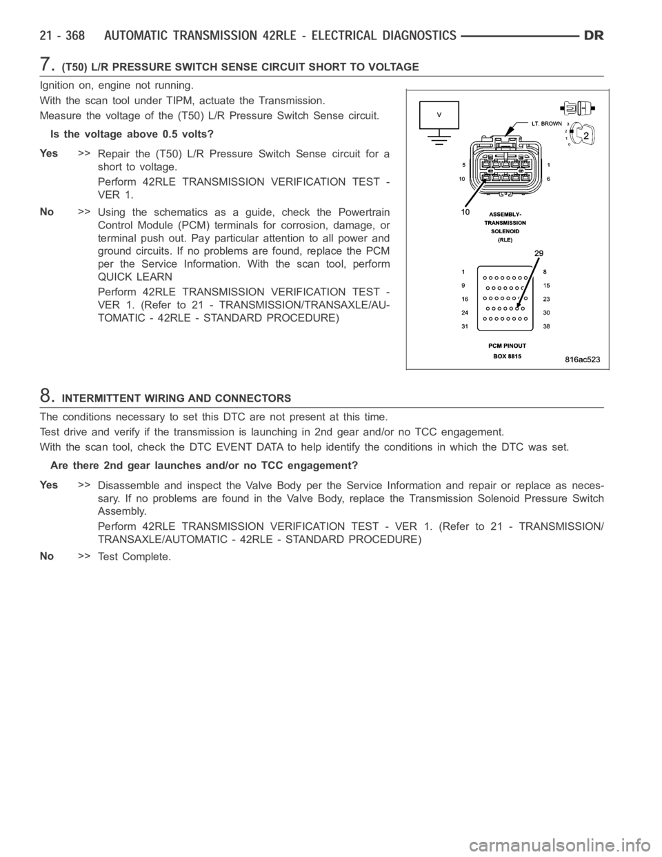
7.(T50) L/R PRESSURE SWITCH SENSE CIRCUIT SHORT TO VOLTAGE
Ignition on, engine not running.
With the scan tool under TIPM, actuate the Transmission.
Measure the voltage of the (T50) L/R Pressure Switch Sense circuit.
Is the voltage above 0.5 volts?
Ye s>>
Repair the (T50) L/R PressureSwitch Sense circuit for a
short to voltage.
Perform 42RLE TRANSMISSION VERIFICATION TEST -
VER 1.
No>>
Using the schematics as a guide, check the Powertrain
Control Module (PCM) terminals for corrosion, damage, or
terminal push out. Pay particular attention to all power and
ground circuits. If no problems are found, replace the PCM
per the Service Information.With the scan tool, perform
QUICK LEARN
Perform 42RLE TRANSMISSION VERIFICATION TEST -
VER 1. (Refer to 21 - TRANSMISSION/TRANSAXLE/AU-
TOMATIC - 42RLE - STANDARD PROCEDURE)
8.INTERMITTENT WIRING AND CONNECTORS
The conditions necessary to set this DTC are not present at this time.
Test drive and verify if the transmission is launching in 2nd gear and/or noTCC engagement.
With the scan tool, check the DTC EVENT DATA to help identify the conditionsin which the DTC was set.
Are there 2nd gear launches and/or no TCC engagement?
Ye s>>
Disassemble and inspect the Valve Body per the Service Information and repair or replace as neces-
sary. If no problems are found in the Valve Body, replace the Transmission Solenoid Pressure Switch
Assembly.
Perform 42RLE TRANSMISSION VERIFICATION TEST - VER 1. (Refer to 21 - TRANSMISSION/
TRANSAXLE/AUTOMATIC - 42RLE - STANDARD PROCEDURE)
No>>
Te s t C o m p l e t e .