2006 DODGE RAM SRT-10 service
[x] Cancel search: servicePage 3704 of 5267
When Monitored:
With the ignition on. Battery voltage greater than 10 volts.
Set Condition:
An open condition is detected in the TIPM on the Transmission Control Output circuit.
Possible Causes
(T16) TRANSMISSION CONTROL OUTPUT CIRCUIT OPEN
TOTALLY INTEGRATED POWER MODULE (TIPM)
Diagnostic Test
1.CHECK IF THE DTC IS ACTIVE
Ignition on, engine not running.
With the scan tool, select View DTCs.
Is the status Active for this DTC?
Ye s>>
Go to 2
No>>
Go to 4
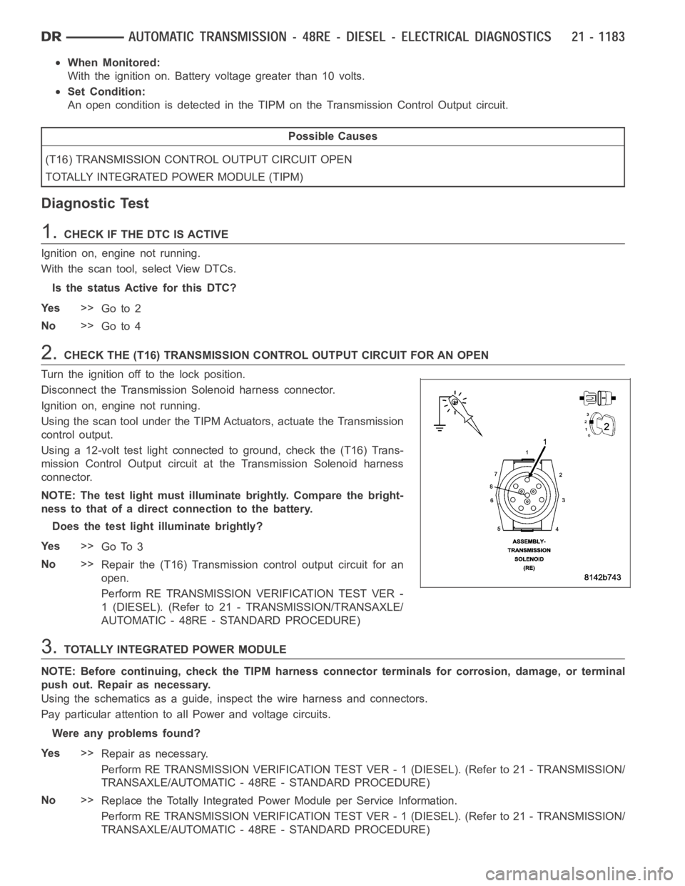
2.CHECK THE (T16) TRANSMISSION CONTROL OUTPUT CIRCUIT FOR AN OPEN
Turn the ignition off to the lock position.
Disconnect the Transmission Solenoid harness connector.
Ignition on, engine not running.
Using the scan tool under the TIPM Actuators, actuate the Transmission
control output.
Using a 12-volt test light connected to ground, check the (T16) Trans-
mission Control Output circuit at the Transmission Solenoid harness
connector.
NOTE: The test light must illuminate brightly. Compare the bright-
ness to that of a direct connection to the battery.
Does the test light illuminate brightly?
Ye s>>
Go To 3
No>>
Repair the (T16) Transmission control output circuit for an
open.
Perform RE TRANSMISSION VERIFICATION TEST VER -
1 (DIESEL). (Refer to 21 - TRANSMISSION/TRANSAXLE/
AUTOMATIC - 48RE - STANDARD PROCEDURE)
3.TOTALLY INTEGRATED POWER MODULE
NOTE: Before continuing, check the TIPM harness connector terminals for corrosion, damage, or terminal
push out. Repair as necessary.
Using the schematics as a guide, inspect the wire harness and connectors.
Pay particular attention to allPower and voltage circuits.
Were any problems found?
Ye s>>
Repair as necessary.
Perform RE TRANSMISSION VERIFICATION TEST VER - 1 (DIESEL). (Refer to 21 - TRANSMISSION/
TRANSAXLE/AUTOMATIC - 48RE - STANDARD PROCEDURE)
No>>
Replace the Totally Integrated Power Module per Service Information.
Perform RE TRANSMISSION VERIFICATION TEST VER - 1 (DIESEL). (Refer to 21 - TRANSMISSION/
TRANSAXLE/AUTOMATIC - 48RE - STANDARD PROCEDURE)
Page 3708 of 5267
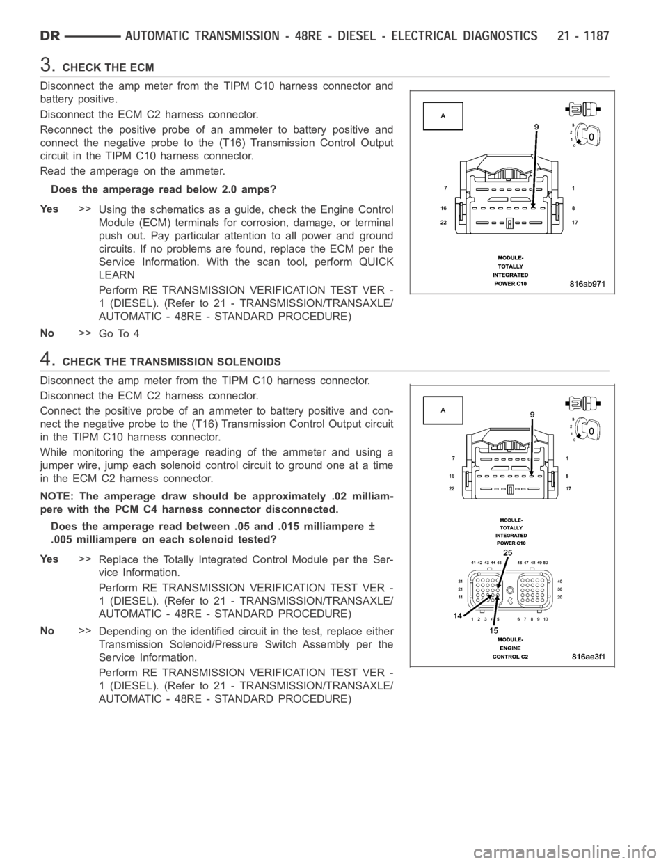
3.CHECK THE ECM
Disconnect the amp meter from the TIPM C10 harness connector and
battery positive.
Disconnect the ECM C2 harness connector.
Reconnect the positive probe of an ammeter to battery positive and
connect the negative probe to the (T16) Transmission Control Output
circuit in the TIPM C10 harness connector.
Read the amperage on the ammeter.
Does the amperage read below 2.0 amps?
Ye s>>
Using the schematics as a guide, check the Engine Control
Module (ECM) terminals for corrosion, damage, or terminal
push out. Pay particular attention to all power and ground
circuits. If no problems are found, replace the ECM per the
Service Information. With the scan tool, perform QUICK
LEARN
Perform RE TRANSMISSION VERIFICATION TEST VER -
1 (DIESEL). (Refer to 21 - TRANSMISSION/TRANSAXLE/
AUTOMATIC - 48RE - STANDARD PROCEDURE)
No>>
Go To 4
4.CHECK THE TRANSMISSION SOLENOIDS
Disconnect the amp meter from theTIPM C10 harness connector.
Disconnect the ECM C2 harness connector.
Connect the positive probe of an ammeter to battery positive and con-
nect the negative probe to the (T16) Transmission Control Output circuit
in the TIPM C10 harness connector.
While monitoring the amperage reading of the ammeter and using a
jumper wire, jump each solenoid control circuit to ground one at a time
in the ECM C2 harness connector.
NOTE: The amperage draw should be approximately .02 milliam-
pere with the PCM C4 harness connector disconnected.
Does the amperage read between .05 and .015 milliampere ±
.005 milliampere on each solenoid tested?
Ye s>>
Replace the Totally Integrated Control Module per the Ser-
vice Information.
Perform RE TRANSMISSION VERIFICATION TEST VER -
1 (DIESEL). (Refer to 21 - TRANSMISSION/TRANSAXLE/
AUTOMATIC - 48RE - STANDARD PROCEDURE)
No>>
Depending on the identified circuit in the test, replace either
Transmission Solenoid/Pressure Switch Assembly per the
Service Information.
Perform RE TRANSMISSION VERIFICATION TEST VER -
1 (DIESEL). (Refer to 21 - TRANSMISSION/TRANSAXLE/
AUTOMATIC - 48RE - STANDARD PROCEDURE)
Page 3712 of 5267
7.GOVERNOR PRESSURE SYSTEM TEST
Turn the ignition off to the lock position.
Connect a 0 to 2068 Kpa or 0 to 300 psi pressure gauge to the Overdrive Clutch Test Port.
Connect a 0 to 2068 Kpa or 0 to 300 psi pressure gauge to the Governor Test Port.
Start the engine.
NOTE: Allow the transmission temperature to rise to normal operating temperature.
While observing both pressure gauges, select 4th Gear from Gov and 3-4 System Test.
NOTE: The Governor pressure should rise to above 137.8 Kpa or 20 psi, shortly after the OD pressure
should rise above 275.7 Kpa or 40 psi.
Did the pressures act as described?
Ye s>>
Go To 8
No>>
Go To 9
8.CHECK IF THE OIL PAN CONTAINS EXCESSIVE DEBRIS
Remove the transmission oil pan per the Service information.
Is the transmission fluid burnt or does the transmission oil pan contain excessive debris?
Ye s>>
Repair internal transmission as necessary. (Refer to 21 - TRANSMISSION/TRANSAXLE/AUTOMATIC -
48RE - REMOVAL)
Perform RE TRANSMISSION VERIFICATION TEST VER - 1 (DIESEL). (Refer to 8 - ELECTRICAL/
ELECTRONIC CONTROL MODULES/TRANSMISSION CONTROL MODULE - DIAGNOSIS ANDTEST-
ING)
No>>
Go To 10
9.CHECK THE 3-4 SHIFT SOLENOID
Turn the ignition off to the lock position.
Replace the 3-4 Solenoid per the Service information. (Refer to 21 - TRANSMISSION/TRANSAXLE/AUTOMATIC -
4 8 R E / VA LV E B O D Y - R E M O VA L )
Connect a 0 to 2068 Kpa or 0 to 300 psi pressure gauge to the Overdrive Clutch Test Port.
Connect a 0 to 2068 Kpa or 0 to 300 psi pressure gauge to the Governor Test Port.
Start the engine.
NOTE: Allow the transmission temperature to rise to normal operating temperature.
While observing both pressure gauges, select 4th gear from the Governor 3-4 shift valve system test.
NOTE: The Governor pressure should rise above 137.8 Kpa or 20 psi, shortly after the OD pressure should
riseabove275.7Kpaor40psi.
Did the pressures act as described?
Ye s>>
Te s t C o m p l e t e .
No>>
Overhaul the transmission per the Service information. Carefully inspect the seals and clutches related
to the OD Clutch. (Refer to 21 - TRANSMISSION/TRANSAXLE/AUTOMATIC - 48RE -REMOVAL)
Perform RE TRANSMISSION VERIFICATION TEST VER - 1 (DIESEL). (Refer to 21 - TRANSMISSION/
TRANSAXLE/AUTOMATIC - 48RE - STANDARD PROCEDURE)
Page 3713 of 5267
10.TORQUE CONVERTER CLUTCH
Turn the ignition on.
With the scan tool, perform the Torque Converter Clutch test.
Did the engine stall?
Ye s>>
Go To 11
No>>
Go To 13
11 .GOVERNOR 3-4 SHIFT VALVE
Start the engine.
Perform the Governor and 3-4 Shift Valve System Test, select 4th gear.
Did the engine stall?
Ye s>>
Go To 12
No>>
Go To 13
12.TCC SOLENOID
Replace the TCC Solenoid. (Refer to 21 - TRANSMISSION/TRANSAXLE/AUTOMATIC - 48RE/VALVE BODY -
REMOVAL)
With the scan tool, perform the Governor and 3-4 Solenoid test, select 4th gear.
Did the engine stall?
Ye s>>
Repair internal transmission as necessary. Check for blocked passages. (Refer to 21 - TRANSMIS-
SION/TRANSAXLE/AUTOMATIC - 48RE - REMOVAL)
Perform RE TRANSMISSION VERIFICATION TEST VER - 1 (DIESEL). (Refer to 21 - TRANSMISSION/
TRANSAXLE/AUTOMATIC - 48RE - STANDARD PROCEDURE)
No>>
Te s t C o m p l e t e .
Perform RE TRANSMISSION VERIFICATION TEST VER - 1 (DIESEL). (Refer to 21 - TRANSMISSION/
TRANSAXLE/AUTOMATIC - 48RE - STANDARD PROCEDURE)
13.SHAFT OR SEAL DAMAGE
Remove the Transmission Oil Pump per the Service information. (Refer to 21- TRANSMISSION/TRANSAXLE/AU-
TOMATIC - 48RE/OIL PUMP - DISASSEMBLY)
Inspect the Reaction shaft, Input Shaft and Input seal.
Are any of the parts damaged or worn?
Ye s>>
Repair as necessary, also replace the Torque Converter.
Perform RE TRANSMISSION VERIFICATION TEST VER - 1 (DIESEL). (Refer to 21 - TRANSMISSION/
TRANSAXLE/AUTOMATIC - 48RE - STANDARD PROCEDURE)
No>>
Replace the Torque Converter. NOTE: Inspect the Reaction Shaft, Input Shaft and Input Seal. Replace
as necessary if any of the parts are damaged or worn.
Perform RE TRANSMISSION VERIFICATION TEST VER - 1 (DIESEL). (Refer to 21 - TRANSMISSION/
TRANSAXLE/AUTOMATIC - 48RE - STANDARD PROCEDURE)
Page 3714 of 5267
14.INTERMITTENT WIRING & CONNECTORS
The conditions necessary to set this DTC are not present at this time.
Use the Freeze Frame Data to help duplicate the conditions in which the DTC originally set. Pay particular attention
to the DTC set conditions, such as, VSS, MAP, ECT, and Load
Using the schematics as a guide, visually inspect the related wiring harness. Look for any chafed, pierced, pinched,
or partially broken wires.
Visually inspect the related wiring harness connectors. Look for broken,bent, pushed out, or corroded terminals.
Wiggle the wiring and connectors while checking for any possible open or shorted circuits.
Check for any Service Information Tune-ups or Technical Service Bulletins that may apply.
Were there any problems found?
Ye s>>
Repair as necessary.
Perform RE TRANSMISSION VERIFICATION TEST VER - 1 (DIESEL). (Refer to 21 - TRANSMISSION/
TRANSAXLE/AUTOMATIC - 48RE - STANDARD PROCEDURE)
No>>
Te s t C o m p l e t e .
Page 3716 of 5267
Theory of Operation
The transmission throttle valve cable has been replace by the transmission throttle valve actuator (TTVA). The TTVA
consists of an electric DC motor, two potentiometers, and a gear drive system. The TTVA is mechanically connected
to the transmission throttle valve in the valve body by the “D” shaped opening in the bottom of the TTVA shaft.
The Transmission Throttle Valve Actuator (TTVA) does not require any mechanical adjustments. All changes in throt-
tle valve position are controlled by the Engine Control Module (ECM).
The TTVA does require an initialization period after the actuator has beenremoved or replaced. After the actuator
has been removed or replaced, move the ignition to the ON position for thirty (30) seconds. This will allow the ECM
sufficient time to perform the internal calibration procedures to learn the TTVA’s current “zero” position.
When Monitored:
Continuously with the ignition on.
Set Condition:
When the Engine Control Module (ECM) detects the monitored Transmission Throttle Valve Position Sensor
voltage drops below a predetermined value.
Possible Causes
(K312) TTVA POSITION SENSOR SIGNAL CIRCUIT OPEN
(K312) TTVA POSITION SENSOR SIGNAL CIRCUIT SHORT TO GROUND
(K312) TTVA POSITION SENSOR SIGNAL CIRCUIT SHORT TO ANOTHER CIRCUIT
(F856) 5 VOLT SUPPLY CIRCUIT OPEN
(F856) 5 VOLT SUPPLY CIRCUIT SHORT TO GROUND
(F856) 5 VOLT SUPPLY CIRCUIT SHORT TO ANOTHER CIRCUIT
TRANSMISSION THROTTLE VALVE ACTUATOR
ENGINE CONTROL MODULE
Always perform the Pre-Diagnostic Troubleshooting procedure before proceeding. (Refer to 21 - TRANSMIS-
SION/TRANSAXLE/AUTOMATIC - 48RE - STANDARD PROCEDURE)
Diagnostic Test
1.CHECK THE TTVA
Ignition on, engine not running.
With the scan tool, record and erase Engine DTCs.
Turn the ignition off to the lock position.
Disconnect the TTVA harness connector.
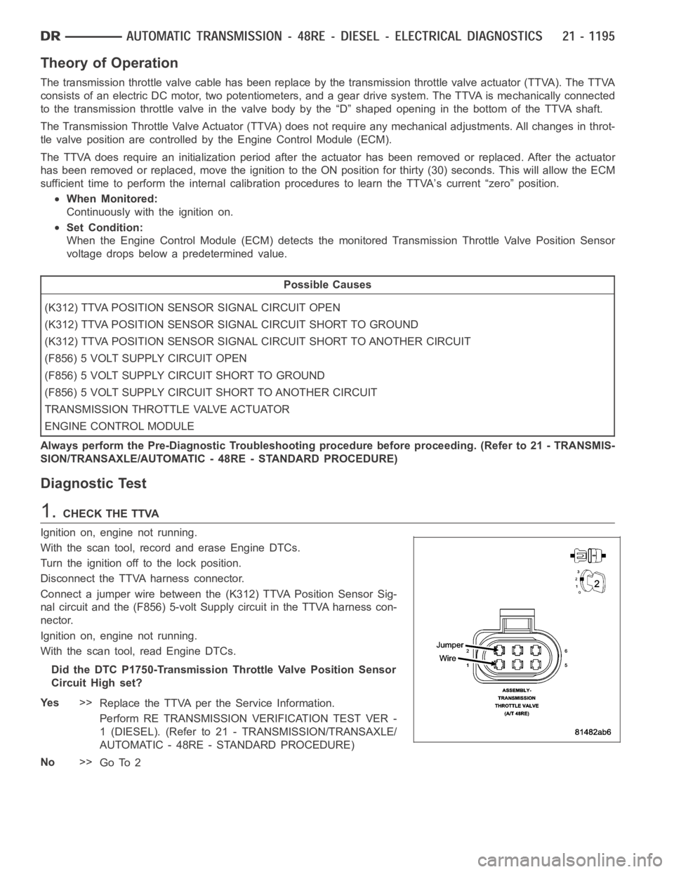
Connect a jumper wire between the (K312) TTVA Position Sensor Sig-
nal circuit and the (F856) 5-volt Supply circuit in the TTVA harness con-
nector.
Ignition on, engine not running.
With the scan tool, read Engine DTCs.
Did the DTC P1750-Transmission Throttle Valve Position Sensor
Circuit High set?
Ye s>>
Replace the TTVA per the Service Information.
Perform RE TRANSMISSION VERIFICATION TEST VER -
1 (DIESEL). (Refer to 21 - TRANSMISSION/TRANSAXLE/
AUTOMATIC - 48RE - STANDARD PROCEDURE)
No>>
Go To 2
Page 3720 of 5267
8.CHECK THE TTVA
Ignition on, engine not running.
With the scan tool, record and erase Engine DTCs.
Turn the ignition off to the lock position.
Disconnect the TTVA harness connector.
NOTE: Check connectors - Clean/repair as necessary.
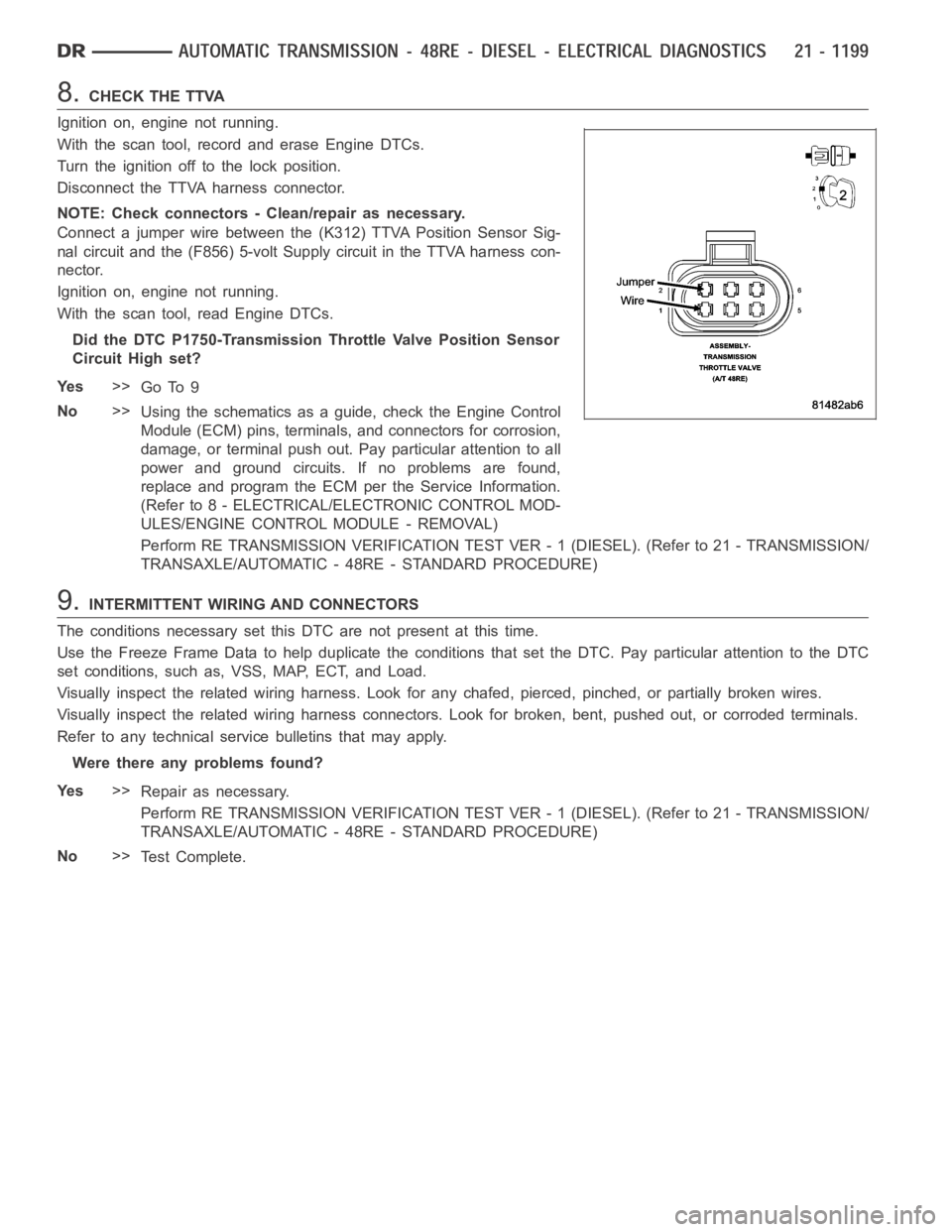
Connect a jumper wire between the (K312) TTVA Position Sensor Sig-
nal circuit and the (F856) 5-volt Supply circuit in the TTVA harness con-
nector.
Ignition on, engine not running.
With the scan tool, read Engine DTCs.
Did the DTC P1750-Transmission Throttle Valve Position Sensor
Circuit High set?
Ye s>>
Go To 9
No>>
Using the schematics as a guide, check the Engine Control
Module (ECM) pins, terminals, and connectors for corrosion,
damage, or terminal push out. Pay particular attention to all
power and ground circuits. If no problems are found,
replace and program the ECM per the Service Information.
(Refer to 8 - ELECTRICAL/ELECTRONIC CONTROL MOD-
ULES/ENGINE CONTROL MODULE - REMOVAL)
Perform RE TRANSMISSION VERIFICATION TEST VER - 1 (DIESEL). (Refer to 21 - TRANSMISSION/
TRANSAXLE/AUTOMATIC - 48RE - STANDARD PROCEDURE)
9.INTERMITTENT WIRING AND CONNECTORS
The conditions necessary set this DTC are not present at this time.
Use the Freeze Frame Data to help duplicate the conditions that set the DTC.Pay particular attention to the DTC
set conditions, such as, VSS, MAP, ECT, and Load.
Visually inspect the related wiring harness. Look for any chafed, pierced, pinched, or partially broken wires.
Visually inspect the related wiring harness connectors. Look for broken,bent, pushed out, or corroded terminals.
Refer to any technical service bulletins that may apply.
Were there any problems found?
Ye s>>
Repair as necessary.
Perform RE TRANSMISSION VERIFICATION TEST VER - 1 (DIESEL). (Refer to 21 - TRANSMISSION/
TRANSAXLE/AUTOMATIC - 48RE - STANDARD PROCEDURE)
No>>
Te s t C o m p l e t e .
Page 3723 of 5267
3.CHECK THE (K900) SENSOR GROUND CIRCUIT FOR AN OPEN
Ignition on, engine not running.
With the scan tool, record and erase Engine DTCs.
Turn the ignition off to the lock position.
Disconnect the TTVA harness connector.
NOTE: Check connectors - Clean/repair as necessary.
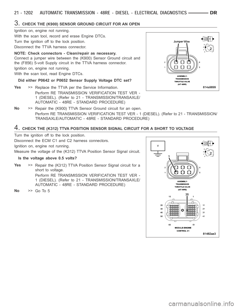
Connect a jumper wire between the (K900) Sensor Ground circuit and
the (F856) 5-volt Supply circuit in the TTVA harness connector.
Ignition on, engine not running.
With the scan tool, read Engine DTCs.
Did either P0642 or P0652 Sensor Supply Voltage DTC set?
Ye s>>
Replace the TTVA per the Service Information.
Perform RE TRANSMISSION VERIFICATION TEST VER -
1 (DIESEL). (Refer to 21 - TRANSMISSION/TRANSAXLE/
AUTOMATIC - 48RE - STANDARD PROCEDURE)
No>>
Repair the (K900) TTVA Sensor Ground circuit for an open.
Perform RE TRANSMISSION VERIFICATION TEST VER - 1 (DIESEL). (Refer to 21 - TRANSMISSION/
TRANSAXLE/AUTOMATIC - 48RE - STANDARD PROCEDURE)
4.CHECK THE (K312) TTVA POSITION SENSOR SIGNAL CIRCUIT FOR A SHORT TO VOLTAGE
Turn the ignition off to the lock position.
Disconnect the ECM C1 and C2 harness connectors.
Ignition on, engine not running.
Measure the voltage of the (K312) TTVA Position Sensor Signal circuit.
Is the voltage above 0.5 volts?
Ye s>>
Repair the (K312) TTVA Position Sensor Signal circuit for a
short to voltage.
Perform RE TRANSMISSION VERIFICATION TEST VER -
1 (DIESEL). (Refer to 21 - TRANSMISSION/TRANSAXLE/
AUTOMATIC - 48RE - STANDARD PROCEDURE)
No>>
Go To 5