Page 2383 of 5267
REMOVAL
1. Raise and support vehicle
2. Disconnect electrical connector (4) at CKP sensor.
3. Remove 1 sensor mounting bolt (3).
4. Remove CKP sensor.
INSTALLATION
1. Position and install CKP sensor (5) to engine.
2. Install 1 sensor mounting bolt and tighten to 9 Nꞏm
(80 in. lbs.) torque.
3. Install electrical connector (4) to CKP sensor.
Page 2392 of 5267

FUEL INJECTOR RAIL
DESCRIPTION
The fuel injector rail is bolted to the top of the intake manifold.
OPERATION
The fuel rail is used as a distribution device to supply high-pressure fuelto the high-pressure fuel lines.
REMOVAL
CAUTION: Cleanliness cannot be overemphasized when handling or replacingdieselfuelsystemcompo-
nents. This especially includes the fuel injectors, high-pressure fuel lines and fuel injection pump. Very tight
tolerances are used with these parts. Dirt contamination could cause rapid part wear and possible plugging
of fuel injector nozzle tip holes. This in turn could lead to possible engine misfire. Always wash/clean any
fuel system component thoroughly before disassembly and then air dry. Capor cover any open part after
disassembly. Before assembly, examine each part for dirt, grease or othercontaminants and clean if nec-
essary. When installing new parts, lubricate them with clean engine oil orclean diesel fuel only.
1. Disconnect both negative battery cables at both
batteries. Isolate ends of both cables.
2. Disconnect electrical connector at fuel pressure
sensor.
3. Remove banjo bolt at fuel limiting valve.
4. Disconnect necessary wiring harness retention
clips from intake manifold.
5. Lift 2 rubber covers to gain access to positive (+),
intake heater cable nuts. Remove 2 nuts and
remove 2 cables from studs.
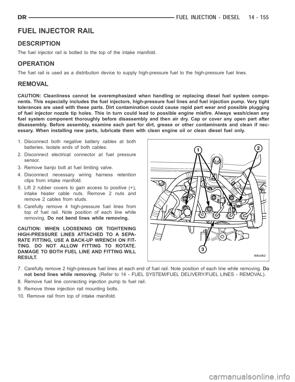
6. Carefully remove 4 high-pressure fuel lines from
top of fuel rail. Note position of each line while
removing.Do not bend lines while removing.
CAUTION: WHEN LOOSENING OR TIGHTENING
HIGH-PRESSURE LINES ATTACHED TO A SEPA-
RATE FITTING, USE A BACK-UP WRENCH ON FIT-
TING. DO NOT ALLOW FITTING TO ROTATE.
DAMAGE TO BOTH FUEL LINE AND FITTING WILL
RESULT.
7. Carefully remove 2 high-pressure fuel lines at each end of fuel rail. Note position of each line while removing.Do
not bend lines while removing.(Refer to 14 - FUEL SYSTEM/FUEL DELIVERY/FUEL LINES - REMOVAL).
8. Remove fuel line connectinginjection pump to fuel rail.
9. Remove three injection rail mounting bolts.
10. Remove rail from top of intake manifold.
Page 2394 of 5267
SENSOR-TEMPERATURE/PRESSURE-INTAKE
DESCRIPTION
The combination, dual function Inlet Air Temperature/
Pressure Sensor (4) is located on the air cleaner (fil-
ter) cover.
OPERATION
The Inlet Air Temperature/Pressure Sensor is a combination dual-function sensor. The sensor element extends into
the intake air stream at the top of the air filter housing. Ambient air temperature as well as barometric pressure is
monitored by this sensor. The Engine Control Module (ECM) monitors signals from this sensor.
REMOVAL
The Inlet Air Temperature/Pressure Sensor is located
on the air cleaner cover.
Page 2395 of 5267
1. Disconnect electrical connector at sensor.
2. Remove two Torx-type mounting screws (3).
3. Remove sensor from air cleaner cover.
4. Check condition of sensor O-ring (2).
Page 2396 of 5267
INSTALLATION
1. Check condition of sensor O-ring.
2. Position sensor into top of air cleaner cover with a
slight twisting action.
3. Install 2 mounting screws (3).
4. Install electrical connector (2).
Page 2402 of 5267
SENSOR-TEMPERATURE/PRESSURE-MAP
DESCRIPTION
The combination, dual function Intake Manifold Air
Temperature Sensor/MAP Sensor (2) is installed into
the top of the intake manifold.
OPERATION
The combination, dual function Intake Manifold Air Temperature Sensor/MAP Sensor is installed into the top of the
intake manifold with the sensor element extending into the air stream.
The IAT portion of the sensor provides an input voltage to the Engine Control Module (ECM) indicating intake man-
ifold air temperature. The MAP portion of the sensor provides an input voltage to the ECM indicating turbocharger
boost pressure.
REMOVAL
The combination, dual function Intake Manifold Air
Temperature Sensor/MAP (IAT/MAP) sensor is
installed (2) into the top of the intake manifold.
1. Clean area around sensor.
2. Disconnect electrical connector (3) from IAT/MAP
sensor.
3. Remove two T-15 Torx headed screws (4).
4. Remove sensor from intake manifold.
Page 2403 of 5267
5. Check condition of sensor O-ring (2).
INSTALLATION
1. Check condition of sensor o-ring.
2. Lubricate sensor o-ring and sensor hole in intake
manifold cover with clean engine oil.
3. Clean sensor mounting area at intake manifold (1).
4. Position sensor (2) into intake manifold.
5. Install and tighten 2 sensor mounting screws to 1
Nꞏm (9 in. lbs.) torque.
6. Connect electrical connector to sensor.
Page 2404 of 5267
SENSOR-MAP
DESCRIPTION
A combination, dual function Intake Manifold Air Temperature Sensor/MAPSensor is used. Refer to Intake Air Tem-
perature Sensor/MAP Sensor for information.