Page 2371 of 5267

MODULE - FUEL TANK
DESCRIPTION
.
The fuel tank module is installed in the top of the fuel tank. The fuel tank module contains the following compo-
nents:
An electric fuel transfer (lift) pump
Fuel reservoir
A separate in-tank fuel filter
Fuel gauge sending unit (fuel level sensor)
Fuel supply line connection
A special lockring to retain module to fuel tank
Fuel return line connection
OPERATION
Refer to Fuel Gauge Sending Unit.
REMOVAL
1. Drain and remove fuel tank (Refer to 14 - FUEL
SYSTEM/FUEL DELIVERY/FUEL TANK -
REMOVAL).
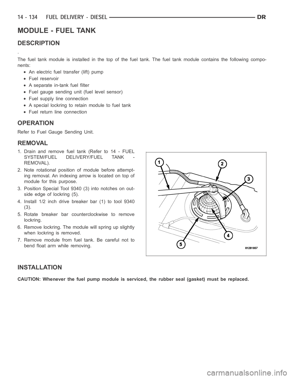
2. Note rotational position of module before attempt-
ing removal. An indexing arrow is located on top of
module for this purpose.
3. Position Special Tool 9340 (3) into notches on out-
side edge of lockring (5).
4. Install 1/2 inch drive breaker bar (1) to tool 9340
(3).
5. Rotate breaker bar counterclockwise to remove
lockring.
6. Remove lockring. The module will spring up slightly
when lockring is removed.
7. Remove module from fuel tank. Be careful not to
bend float arm while removing.
INSTALLATION
CAUTION: Whenever the fuel pump module is serviced, the rubber seal (gasket) must be replaced.
Page 2375 of 5267
SENSOR-WATER IN FUEL
DESCRIPTION
The Water-In-Fuel (WIF) sensor (5) is located on the
side of the fuel filter/water separator canister.
OPERATION
The sensor sends an input to the Engine Control Module (ECM) when it senses water in the fuel filter/water sep-
arator. As the water level in the filter/separator increases, the resistance across the WIF sensor decreases. This
decreaseinresistanceissentasasignaltotheECMandcomparedtoahighwater standard value. Once the value
reaches 30 to 40 kilohms, the ECM will activate the water-in-fuel warning lamp through CCD bus circuits. This all
takes place when the ignition key is initially put in the ON position. The ECM continues to monitor the input while
the engine is running.
REMOVAL
The Water-In-Fuel (WIF) sensor is located at the side of fuel filter/waterseparator canister. (Refer to 14 - FUEL
SYSTEM/FUEL DELIVERY/FUEL TANK MODULE - INSTALLATION).
Page 2377 of 5267

page page
SENSOR-ACCELERATOR PEDAL POSITION
DESCRIPTION ............................... 141
OPERATION ................................. 141
REMOVAL ................................... 141
INSTALLATION .............................. 142
SENSOR-CAMSHAFT POSITION
DESCRIPTION ............................... 143
OPERATION ................................. 143
REMOVAL ................................... 143
INSTALLATION .............................. 144
SENSOR-CRANKSHAFT POSITION
DESCRIPTION ............................... 145
OPERATION ................................. 145
REMOVAL ................................... 146
INSTALLATION .............................. 146
ACTUATOR - FUEL CONTROL
DESCRIPTION ............................... 147
OPERATION ................................. 147
REMOVAL ................................... 147
INSTALLATION .............................. 147
INJECTOR - FUEL
DESCRIPTION ............................... 148
OPERATION ................................. 149
REMOVAL ................................... 149
INSTALLATION .............................. 153
FUEL INJECTOR RAIL
DESCRIPTION ............................... 155
OPERATION ................................. 155REMOVAL ................................... 155
INSTALLATION .............................. 156
SENSOR-TEMPERATURE/PRESSURE-INTAKE
DESCRIPTION ............................... 157
OPERATION ................................. 157
REMOVAL ................................... 157
INSTALLATION .............................. 159
HEATER - INTAKE AIR
DESCRIPTION ............................... 160
OPERATION ................................. 160
REMOVAL ................................... 160
INSTALLATION .............................. 162
RELAY - INTAKE AIR HEATER
DESCRIPTION ............................... 163
OPERATION ................................. 163
REMOVAL ................................... 163
INSTALLATION .............................. 164
SENSOR-TEMPERATURE/PRESSURE-MAP
DESCRIPTION ............................... 165
OPERATION ................................. 165
REMOVAL ................................... 165
INSTALLATION .............................. 166
SENSOR-MAP
DESCRIPTION ............................... 167
SWITCH - PTO
DESCRIPTION ............................... 168
OPERATION ................................. 168
Page 2378 of 5267
SENSOR-ACCELERATOR PEDAL POSITION
DESCRIPTION
The Accelerator Pedal Position Sensor (APPS) (1) is
located inside the vehicle.It is attached to the accel-
erator pedal assembly (3).
OPERATION
The Accelerator Pedal Position Sensor (APPS) provides the Engine ControlModule (ECM) with two DC voltage
signals which change as the position of the accelerator pedal changes. Oneof the DC voltage signals will be half
the voltage of the other signal.
REMOVAL
CAUTION: Do not attempt to separate or remove the Accelerator Pedal Position Sensor (APPS) from the
accelerator pedal assembly. The APPS is replaced as an assembly along withthe pedal. If sensor is
removed from pedal, its electronic calibration may be destroyed.
1. Disconnect 6–way electrical connector at top of
APPS (2).
2. Remove APPS lower mounting bolt (4) and two
mounting nuts.
3. Remove pedal and APPS assembly from vehicle.
Page 2379 of 5267
INSTALLATION
CAUTION: Do not attempt to separate or remove the Accelerator Pedal Position Sensor (APPS) from the
accelerator pedal assembly. The APPS is replaced as an assembly along withthe pedal. If sensor is
removed from pedal, its electronic calibration may be destroyed.
1. Position pedal and APPS assembly to its mounting
bracket.
2. Connect 6–way electrical connector to top of APPS
(2).
3. Install APPS lower mounting bolt (4) and two
mounting nuts.
4. If necessary, use a Scan Tool to erase any Diag-
nostic Trouble Codes (DTC’s).
Page 2380 of 5267

SENSOR-CAMSHAFT POSITION
DESCRIPTION
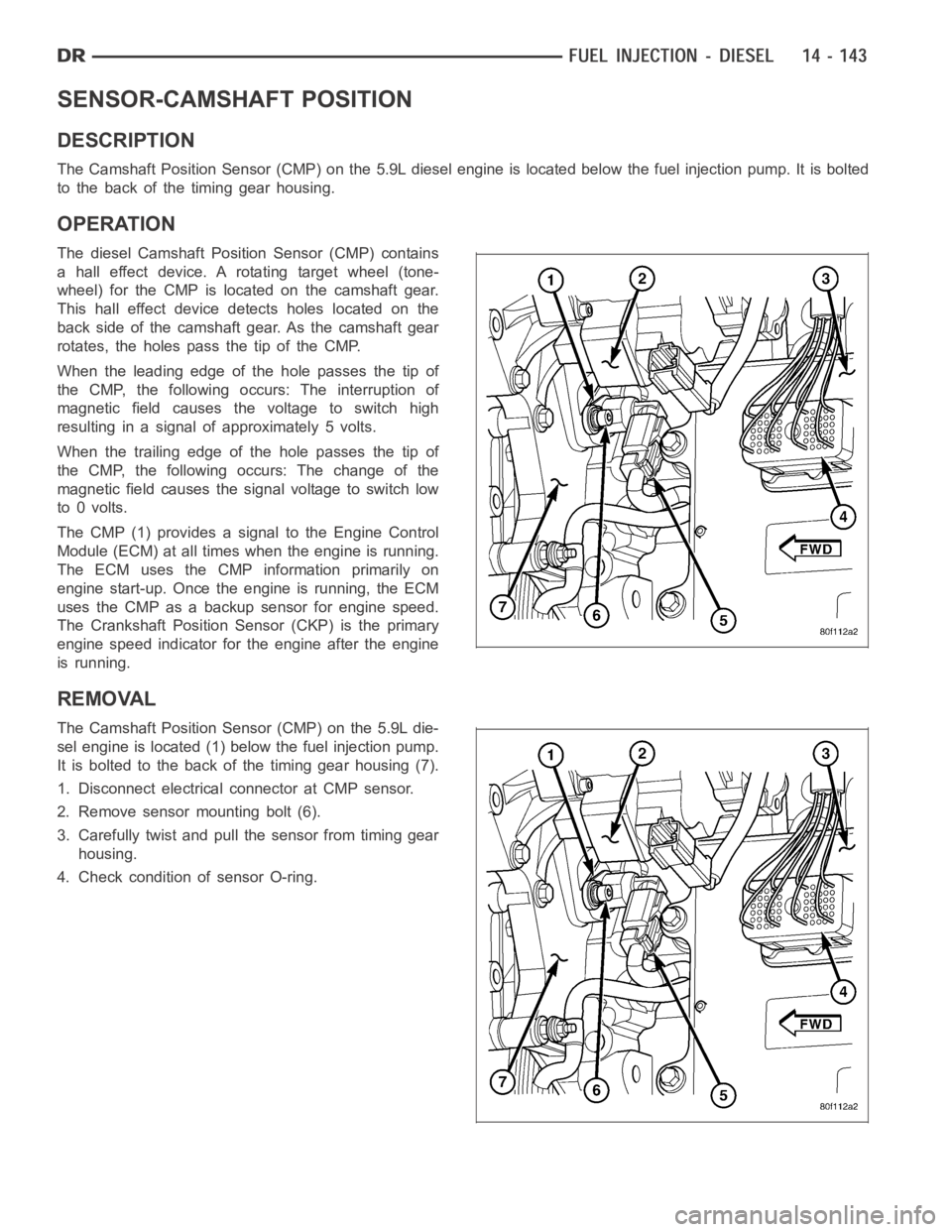
The Camshaft Position Sensor (CMP) on the 5.9L diesel engine is located below the fuel injection pump. It is bolted
to the back of the timing gear housing.
OPERATION
The diesel Camshaft Position Sensor (CMP) contains
a hall effect device. A rotating target wheel (tone-
wheel) for the CMP is located on the camshaft gear.
This hall effect device detects holes located on the
back side of the camshaft gear. As the camshaft gear
rotates, the holes pass the tip of the CMP.
When the leading edge of the hole passes the tip of
the CMP, the following occurs: The interruption of
magnetic field causes the voltage to switch high
resulting in a signal of approximately 5 volts.
When the trailing edge of the hole passes the tip of
the CMP, the following occurs: The change of the
magnetic field causes the signal voltage to switch low
to 0 volts.
The CMP (1) provides a signal to the Engine Control
Module (ECM) at all times when the engine is running.
TheECMusestheCMPinformationprimarilyon
engine start-up. Once the engine is running, the ECM
uses the CMP as a backup sensor for engine speed.
The Crankshaft Position Sensor (CKP) is the primary
engine speed indicator for the engine after the engine
is running.
REMOVAL
The Camshaft Position Sensor (CMP) on the 5.9L die-
sel engine is located (1) below the fuel injection pump.
It is bolted to the back of the timing gear housing (7).
1. Disconnect electrical connector at CMP sensor.
2. Remove sensor mounting bolt (6).
3. Carefully twist and pull the sensor from timing gear
housing.
4. Check condition of sensor O-ring.
Page 2381 of 5267
INSTALLATION
1. Clean out machined hole in back of timing gear
housing.
2. Apply a small amount of engine oil to sensor O-ring
and sensor hole.
3. Install sensor into timing gear housing with a slight
rocking action. Do not twist sensor into position as
damagetoO-ringmayresult.
CAUTION: Before tightening sensor mounting bolt,
be sure sensor is completely flush to back of tim-
ing gear housing (cover). Remove (cover) if sensor
is not flush, damage to sensor mounting tang may
result.
4. Install mounting bolt and tighten. Torque to 9 Nꞏm
(80 in. lbs.).
5. Connect electrical connector (5) to sensor.
Page 2382 of 5267

SENSOR-CRANKSHAFT POSITION
DESCRIPTION
The Crankshaft Position Sensor (CKP) on the diesel engine is attached at thefront/leftsideoftheenginenextto
the engine harmonic balancer (crankshaft damper).
OPERATION
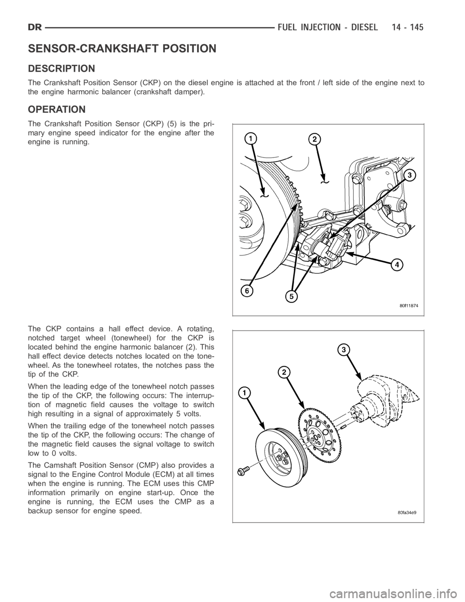
The Crankshaft Position Sensor (CKP) (5) is the pri-
mary engine speed indicator for the engine after the
engine is running.
The CKP contains a hall effect device. A rotating,
notched target wheel (tonewheel) for the CKP is
located behind the engine harmonic balancer (2). This
hall effect device detects notches located on the tone-
wheel. As the tonewheel rotates, the notches pass the
tip of the CKP.
When the leading edge of the tonewheel notch passes
the tip of the CKP, the following occurs: The interrup-
tion of magnetic field causes the voltage to switch
high resulting in a signal of approximately 5 volts.
When the trailing edge of the tonewheel notch passes
the tip of the CKP, the following occurs: The change of
the magnetic field causes the signal voltage to switch
lowto0volts.
The Camshaft Position Sensor (CMP) also provides a
signal to the Engine Control Module (ECM) at all times
when the engine is running. The ECM uses this CMP
information primarily on engine start-up. Once the
engine is running, the ECM uses the CMP as a
backup sensor for engine speed.