Page 4077 of 5267

6.FRONT AXLE DISCONNECT (FAD) MODULE
Using the wiring diagram/schematic as a guide, inspect all wiring and connectors that pertain to this circuit.
Were any problems found?
Ye s>>
Repair as necessary.
Perform the TRANSFER CASE VERIFICATION TEST-VER 1. (Refer to 21 - TRANSMISSION/TRANS-
AXLE/TRANSFER CASE - STANDARD PROCEDURE)
No>>
Replace the Front Axle Disconnect (FAD) Module in accordance with the Service Information.
Perform the TRANSFER CASE VERIFICATION TEST-VER 1. (Refer to 21 - TRANSMISSION/TRANS-
AXLE/TRANSFER CASE - STANDARD PROCEDURE)
7.INTERMITTENT WIRING AND CONNECTORS
The conditions necessary to set this DTC are not present at this time.
Using the schematics as a guide, inspect the wiring and connectors specifictothiscircuit.
Wiggle test the wiring harness and connectors while checking for shorted and open circuits.
Using the scan tool, monitor the data related to this circuit while performing the wiggle test. Look for the data to
change or for the DTC to reset.
Were there any problems found?
Ye s>>
Repair as necessary.
Perform the TRANSFER CASE VERIFICATION TEST-VER 1. (Refer to 21 - TRANSMISSION/TRANS-
AXLE/TRANSFER CASE - STANDARD PROCEDURE)
No>>
Te s t C o m p l e t e .
Page 4078 of 5267
C146A–FRONT AXLE DISCONNECTRETURN CONTROL CIRCUIT OPEN
For a complete wiring diagramRefer to Section 8W.
Page 4082 of 5267

7.FRONT AXLE DISCONNECT (FAD) MODULE
Using the wiring diagram/schematic as a guide, inspect all wiring and connectors that pertain to this circuit.
Were any problems found?
Ye s>>
Repair as necessary.
Perform the TRANSFER CASE VERIFICATION TEST-VER 1. (Refer to 21 - TRANSMISSION/TRANS-
AXLE/TRANSFER CASE - STANDARD PROCEDURE)
No>>
Replace the Front Axle Disconnect (FAD) Module in accordance with the Service Information.
Perform the TRANSFER CASE VERIFICATION TEST-VER 1. (Refer to 21 - TRANSMISSION/TRANS-
AXLE/TRANSFER CASE - STANDARD PROCEDURE)
8.TOTALLY INTEGRATED POWER MODULE (TIPM)
Using the wiring diagram/schematic as a guide, inspect all wiring and connectors that pertain to this circuit.
Were any problems found?
Ye s>>
Repair as necessary.
Perform the TRANSFER CASE VERIFICATION TEST-VER 1. (Refer to 21 - TRANSMISSION/TRANS-
AXLE/TRANSFER CASE - STANDARD PROCEDURE)
No>>
Replace the Totally Integrated Power Module (TIPM) in accordance with theService Information.
Perform the TRANSFER CASE VERIFICATION TEST-VER 1. (Refer to 21 - TRANSMISSION/TRANS-
AXLE/TRANSFER CASE - STANDARD PROCEDURE)
9.INTERMITTENT WIRING AND CONNECTORS
The conditions necessary to set this DTC are not present at this time.
Using the schematics as a guide, inspect the wiring and connectors specifictothiscircuit.
Wiggle test the wiring harness and connectors while checking for shorted and open circuits.
Using the scan tool, monitor the data related to this circuit while performing the wiggle test. Look for the data to
change or for the DTC to reset.
Were there any problems found?
Ye s>>
Repair as necessary.
Perform the TRANSFER CASE VERIFICATION TEST-VER 1. (Refer to 21 - TRANSMISSION/TRANS-
AXLE/TRANSFER CASE - STANDARD PROCEDURE)
No>>
Te s t C o m p l e t e .
STANDARD PROCEDURE
Page 4610 of 5267

The motor/module is programmed to learn the speed required to drive the panel based on position and recalibrates
itself as needed. If the sunroof becomes uncalibrated, it will only respond to the vent switch. If the vent switch is
pressed, the glass will move toward vent; if the switch is released, all motion stops. In the event that the sunroof
system becomes uncalibrated performthe sunroof position calibration procedure, (Refer to 8 - ELECTRICAL/
POWER TOP/MOTOR - STANDARD PROCEDURE -SUNROOF POSITION CALIBRATION).
DIAGNOSIS AND TESTING
POWER TOP - SUNROOF
Any diagnosis of the power sunroof system should begin with the use of a scantool and the proper Diagnostic
Procedures Information. The scan tool can provide confirmation that the Controller Area Network (CAN) Data Bus is
functional, that all of the electronic modules are sending and receiving the proper messages on the CAN Data Bus,
and that the power sunroof motor is being sent the proper hard wired output by the sunroof switch.
For complete circuit diagrams, refer to the appropriate wiring information. The wiring information includes wiring dia-
grams, proper wire and connector repair procedures, details of wire harness routing and retention, connector pin-out
information and location views for the various wire harness connectors, splices and grounds.
Refer to the appropriate diagnostic information.
SUNROOF
Refer to SUNROOF DIAGNOSIS CHART for possible causes. Before beginning sunroof diagnostics verify that all
other power accessories are in proper operating condition. If not, a common electrical problem may exist. Refer to
Wiring Diagrams, in this publication for circuit, splice and component descriptions. Check the condition of the circuit
protection (20 amp circuit breaker in the Junction Block). Inspect all wiring connector pins for proper engagement
and continuity. Check for battery voltage at the power sunroof controller, refer to Wiring Diagrams, for circuit infor-
mation. If battery voltage of more than 10 volts is detected at the controller, proceed with the following tests (the
controller will not operate at less than 10 volts).
Before beginning diagnosis for wind noise or water leaks, verify that the problem was not caused by releasing the
control switch before the sunroof was fully closed. The sunroof module hasa water-management system. If how-
ever, the sunroof glass is in a partial closed position, high pressure water may be forced beyond the water man-
agement system boundariesand onto the headlining.
Every time the sunroof module loses power it must be initialized. This is done by connecting power to the sunroof
and moving the sunroof toward the closed position. When initialization occurs a slight “kick” in the sunroof module
will be seen and heard. This is the indication that the sunroof module is initialized
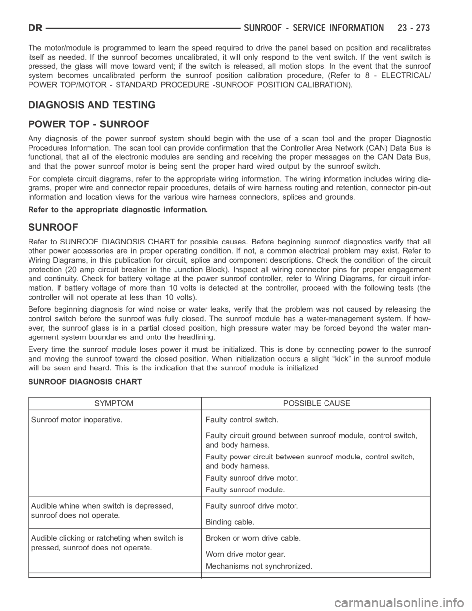
SUNROOF DIAGNOSIS CHART
SYMPTOM POSSIBLE CAUSE
Sunroof motor inoperative. Faulty control switch.
Faulty circuit ground between sunroof module, control switch,
and body harness.
Faulty power circuit between sunroof module, control switch,
and body harness.
Faulty sunroof drive motor.
Faulty sunroof module.
Audible whine when switch is depressed,
sunroof does not operate.Faulty sunroof drive motor.
Binding cable.
Audible clicking or ratcheting when switch is
pressed, sunroof does not operate.Broken or worn drive cable.
Worn drive motor gear.
Mechanisms not synchronized.
Page 4845 of 5267
B10AA–RIGHT BLEND DOOR CONTROL CIRCUIT LOW (DUAL-ZONE)
For a complete wiring diagramRefer to Section 8W.
Page 4848 of 5267

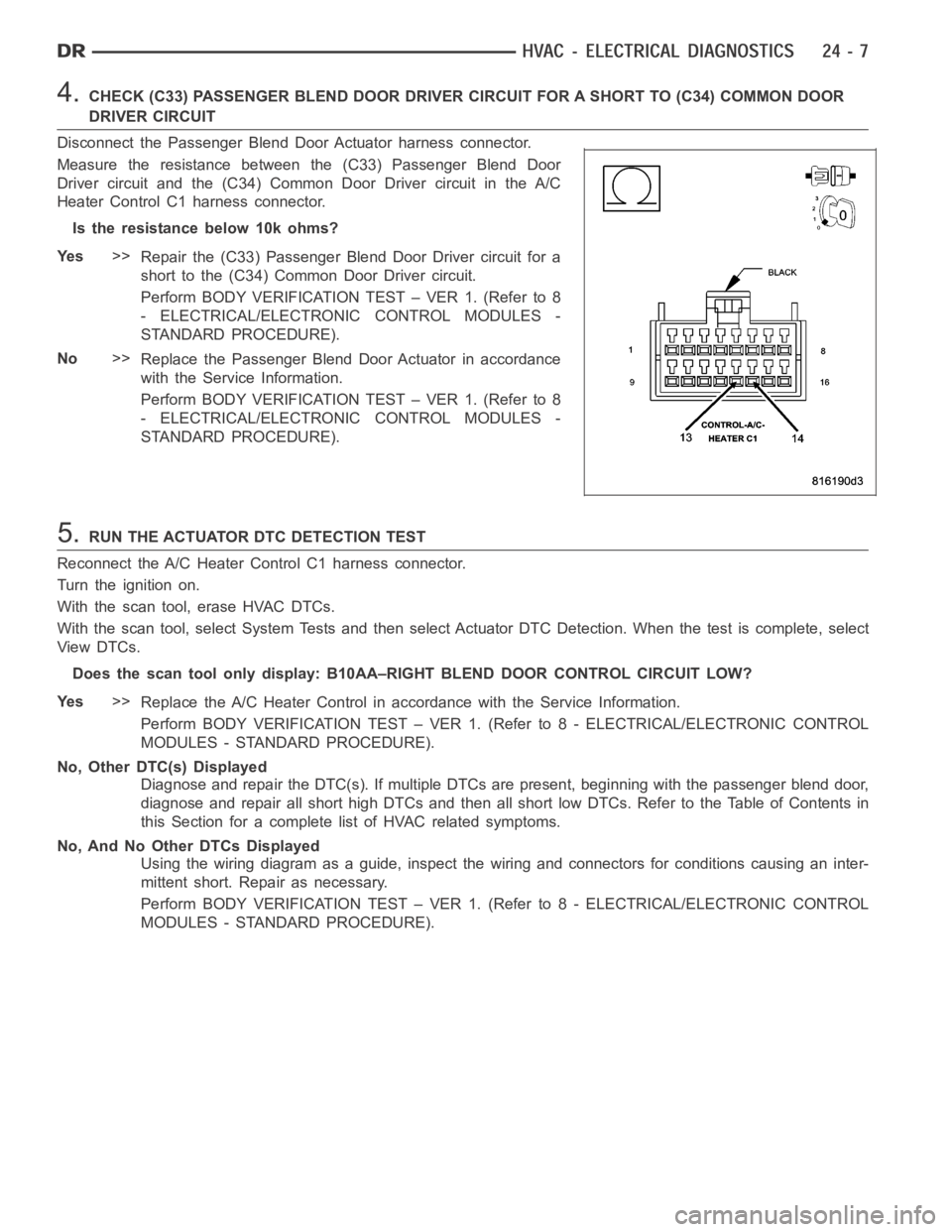
4.CHECK (C33) PASSENGER BLEND DOOR DRIVER CIRCUIT FOR A SHORT TO (C34) COMMONDOOR
DRIVER CIRCUIT
Disconnect the Passenger Blend Door Actuator harness connector.
Measure the resistance between the (C33) Passenger Blend Door
Driver circuit and the (C34) Common Door Driver circuit in the A/C
Heater Control C1 harness connector.
Istheresistancebelow10kohms?
Ye s>>
Repair the (C33) Passenger Blend Door Driver circuit for a
short to the (C34) Common Door Driver circuit.
Perform BODY VERIFICATION TEST – VER 1. (Refer to 8
- ELECTRICAL/ELECTRONIC CONTROL MODULES -
STANDARD PROCEDURE).
No>>
Replace the Passenger Blend Door Actuator in accordance
with the Service Information.
Perform BODY VERIFICATION TEST – VER 1. (Refer to 8
- ELECTRICAL/ELECTRONIC CONTROL MODULES -
STANDARD PROCEDURE).
5.RUN THE ACTUATOR DTC DETECTION TEST
Reconnect the A/C Heater Control C1 harness connector.
Turn the ignition on.
With the scan tool, erase HVAC DTCs.
With the scan tool, select System Tests and then select Actuator DTC Detection. When the test is complete, select
View DTCs.
Does the scan tool only display: B10AA–RIGHT BLEND DOOR CONTROL CIRCUIT LOW?
Ye s>>
Replace the A/C Heater Control in accordance with the Service Information.
Perform BODY VERIFICATION TEST – VER 1. (Refer to 8 - ELECTRICAL/ELECTRONIC CONTROL
MODULES - STANDARD PROCEDURE).
No, Other DTC(s) Displayed
Diagnose and repair the DTC(s). If multiple DTCs are present, beginning with the passenger blend door,
diagnose and repair all short high DTCs and then all short low DTCs. Refer tothe Table of Contents in
this Section for a complete list of HVAC related symptoms.
No, And No Other DTCs Displayed
Using the wiring diagram as a guide, inspect the wiring and connectors for conditions causing an inter-
mittent short. Repair as necessary.
Perform BODY VERIFICATION TEST – VER 1. (Refer to 8 - ELECTRICAL/ELECTRONIC CONTROL
MODULES - STANDARD PROCEDURE).
Page 4849 of 5267
B10AB–RIGHT BLEND DOOR CONTROL CIRCUIT HIGH (DUAL-ZONE)
For a complete wiring diagramRefer to Section 8W.
Page 4851 of 5267
Diagnose and repair the DTC(s). If multiple DTCs are present, beginning with the passenger blend door,
diagnose and repair all short high DTCs and then all short low DTCs. Refer tothe Table of Contents in
this Section for a complete list of HVAC related symptoms.
No, And No Other DTCs Displayed
Using the wiring diagram as a guide, inspect the wiring and connectors for conditions causing an inter-
mittent short. Repair as necessary.
Perform BODY VERIFICATION TEST – VER 1. (Refer to 8 - ELECTRICAL/ELECTRONIC CONTROL
MODULES - STANDARD PROCEDURE).