Page 3804 of 5267

5. Install new pump seal, O-ring, and gasket. Replace oil pump if cracked, porous or damaged in any way. Be sure
to loosen the front band before installing the oil pump, damage to the oil pump seal may occur if the band is still
tightened to the frontclutch retainer.
6. Loosen kickdown lever pin access plug three turns. Apply Loctite™ 592, orPermatex
No. 2 to plug threads and
tightenplugto17Nꞏm(150in.lbs.)torque.
7. Adjust front band.
8. Lubricate pump seal and converter hub with transmission fluid or petroleum jelly and install converter.
9. Install transmission and converter housing dust shield.
10. Lower vehicle.
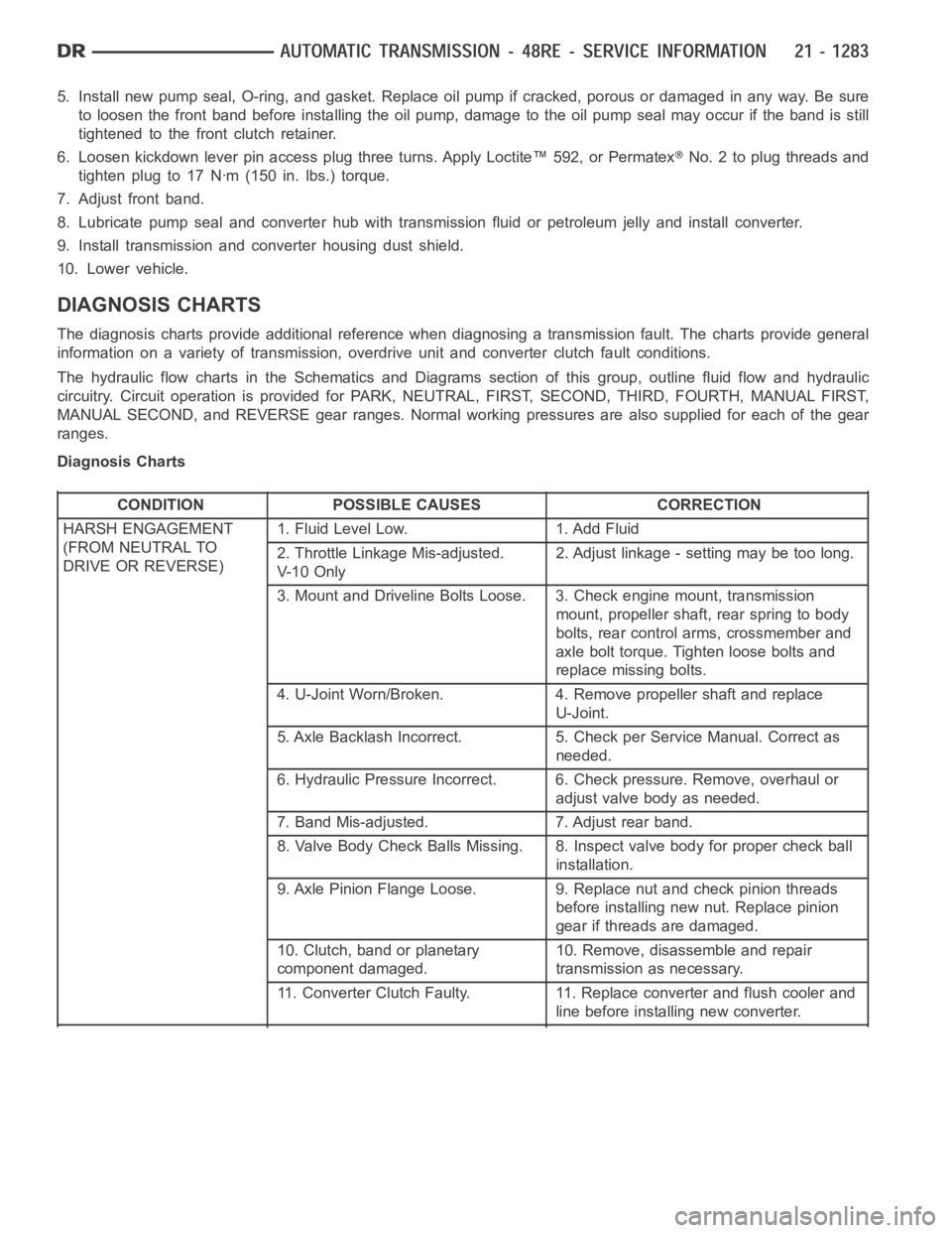
DIAGNOSIS CHARTS
The diagnosis charts provide additional reference when diagnosing a transmission fault. The charts provide general
information on a variety of transmission, overdrive unit and converter clutch fault conditions.
The hydraulic flow charts in the Schematics and Diagrams section of this group, outline fluid flow and hydraulic
circuitry. Circuit operation is provided for PARK, NEUTRAL, FIRST, SECOND, THIRD, FOURTH, MANUAL FIRST,
MANUAL SECOND, and REVERSE gear ranges. Normal working pressures are alsosupplied for each of the gear
ranges.
Diagnosis Charts
CONDITION POSSIBLE CAUSES CORRECTION
HARSH ENGAGEMENT
(FROM NEUTRAL TO
DRIVE OR REVERSE)1. Fluid Level Low. 1. Add Fluid
2. Throttle Linkage Mis-adjusted.
V- 1 0 O n l y2. Adjust linkage - setting may be too long.
3. Mount and Driveline Bolts Loose. 3. Check engine mount, transmission
mount, propeller shaft, rear spring to body
bolts, rear control arms, crossmember and
axle bolt torque. Tighten loose bolts and
replace missing bolts.
4. U-Joint Worn/Broken. 4. Remove propeller shaft and replace
U-Joint.
5. Axle Backlash Incorrect. 5. Check per Service Manual. Correct as
needed.
6. Hydraulic Pressure Incorrect. 6. Check pressure. Remove, overhaul or
adjust valve body as needed.
7. Band Mis-adjusted. 7. Adjust rear band.
8. Valve Body Check Balls Missing. 8. Inspect valve body for proper check ball
installation.
9. Axle Pinion Flange Loose. 9. Replace nut and check pinion threads
before installing new nut. Replace pinion
gear if threads are damaged.
10. Clutch, band or planetary
component damaged.10. Remove, disassemble and repair
transmission as necessary.
11. Converter Clutch Faulty. 11. Replace converter and flush cooler and
line before installing new converter.
Page 3843 of 5267
SCHEMATICS AND DIAGRAMS
HYDRAULIC SCHEMATICS
Page 3975 of 5267

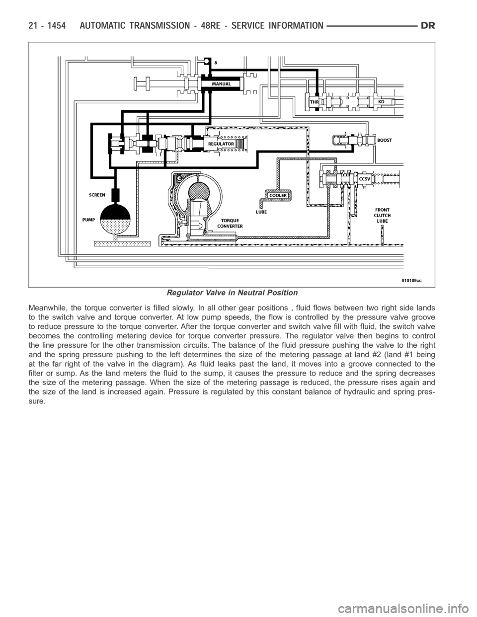
Meanwhile, the torque converter is filled slowly. In all other gear positions , fluid flows between two right side lands
to the switch valve and torque converter. At low pump speeds, the flow is controlled by the pressure valve groove
to reduce pressure to the torque converter. After the torque converter andswitch valve fill with fluid, the switch valve
becomes the controlling metering device for torque converter pressure. The regulator valve then begins to control
the line pressure for the other transmission circuits. The balance of the fluid pressure pushing the valve to the right
and the spring pressure pushing to the left determines the size of the metering passage at land #2 (land #1 being
at the far right of the valve in the diagram). As fluid leaks past the land, itmoves into a groove connected to the
filter or sump. As the land meters the fluid to the sump, it causes the pressure to reduce and the spring decreases
the size of the metering passage. When the size of the metering passage is reduced, the pressure rises again and
the size of the land is increased again. Pressure is regulated by this constant balance of hydraulic and spring pres-
sure.
Regulator Valve in Neutral Position
Page 4022 of 5267
C1401- TRANSFER CASE RANGE SELECT SWITCH CIRCUIT LOW
For a complete wiring diagramRefer to Section 8W
Page 4026 of 5267

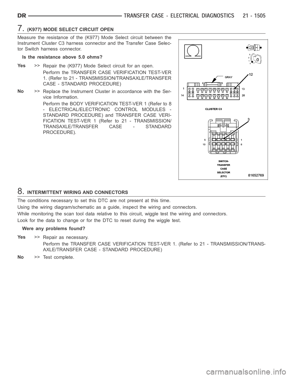
7.(K977) MODE SELECT CIRCUIT OPEN
Measure the resistance of the (K977) Mode Select circuit between the
Instrument Cluster C3 harness connector and the Transfer Case Selec-
tor Switch harness connector.
Is the resistance above 5.0 ohms?
Ye s>>
Repair the (K977) Mode Select circuit for an open.
Perform the TRANSFER CASE VERIFICATION TEST-VER
1. (Refer to 21 - TRANSMISSION/TRANSAXLE/TRANSFER
CASE - STANDARD PROCEDURE)
No>>
Replace the Instrument Cluster in accordance with the Ser-
vice Information.
Perform the BODY VERIFICATION TEST-VER 1 (Refer to 8
- ELECTRICAL/ELECTRONIC CONTROL MODULES -
STANDARD PROCEDURE) and TRANSFER CASE VERI-
FICATION TEST-VER 1 (Refer to 21 - TRANSMISSION/
TRANSAXLE/TRANSFER CASE - STANDARD
PROCEDURE).
8.INTERMITTENT WIRING AND CONNECTORS
The conditions necessary to set this DTC are not present at this time.
Using the wiring diagram/schematic as a guide, inspect the wiring and connectors.
While monitoring the scan tool data relative to this circuit, wiggle test the wiring and connectors.
Look for the data to change or for the DTC to reset during the wiggle test.
Were any problems found?
Ye s>>
Repair as necessary.
Perform the TRANSFER CASE VERIFICATION TEST-VER 1. (Refer to 21 - TRANSMISSION/TRANS-
AXLE/TRANSFER CASE - STANDARD PROCEDURE)
No>>
Te s t c o m p l e t e .
Page 4027 of 5267
C1402- TRANSFER CASE RANGE SELECT SWITCH CIRCUIT HIGH
For a complete wiring diagramRefer to Section 8W
Page 4031 of 5267
7.INSTRUMENT CLUSTER
Repair
Replace the Instrument Cluster in accordance with the Service Information.
Perform the BODY VERIFICATION TEST-VER 1 (Refer to 8 - ELECTRICAL/ELECTRONIC CONTROL
MODULES - STANDARD PROCEDURE) and TRANSFER CASE VERIFICATION TEST-VER 1 (Refer to
21 - TRANSMISSION/TRANSAXLE/TRANSFER CASE - STANDARD PROCEDURE).
8.INTERMITTENT WIRING AND CONNECTORS
The conditions necessary to set this DTC are not present at this time.
Using the wiring diagram/schematic as a guide, inspect the wiring and connectors.
While monitoring the scan tool data relative to this circuit, wiggle test the wiring and connectors.
Look for the data to change or for the DTC to reset during the wiggle test.
Were any problems found?
Ye s>>
Repair as necessary.
Perform the TRANSFER CASE VERIFICATION TEST-VER 1. (Refer to 21 - TRANSMISSION/TRANS-
AXLE/TRANSFER CASE - STANDARD PROCEDURE)
No>>
Te s t c o m p l e t e .
Page 4032 of 5267
C1404- TRANSFER CASE RANGE POSITION SENSOR CIRCUIT LOW
For a complete wiring diagramRefer to Section 8W