2006 DODGE RAM SRT-10 heating
[x] Cancel search: heatingPage 3959 of 5267
VALVE-TORQUE CONVERTER DRAINBACK
DESCRIPTION
GAS ENGINES
The drainback valve is located in the transmission cooler outlet (pressure) line.
DIESEL ENGINE
The converter drainback check valve is located in the in the TOC pressure - supply line, between the engine
mounted TOC and the air to oil TOC.
OPERATION
GAS ENGINES
The valve prevents fluid from draining from the converter into the cooler and lines when the vehicle is shut down for
lengthy periods. Production valves have a hose nipple at one end, while theopposite end is threaded for a flare
fitting. All valves have an arrow (or similar mark) to indicate direction of flow through the valve.
DIESEL ENGINE
The valve prevents fluid from draining from the converter into the cooler and lines when the vehicle is shut down for
lengthy periods. Production valves have pipe thread on one end, while the opposite end is threaded for a flare
fitting, and are threaded into the oil cooler mounted on the side of the engine. All valves have an arrow (or similar
mark) to indicate direction of flow through the valve.
STANDARD PROCEDURE
GAS ENGINES
The converter drainback check valve is located in the cooler outlet (pressure) line near the radiator tank. The valve
prevents fluid drainback when the vehicle is parked for lengthy periods. The valve check ball is spring loaded and
has an opening pressure of approximately 2 psi.
The valve is serviced as an assembly; it is not repairable. Do not clean the valve if restricted, or contaminated by
sludge, or debris. If the valve fails, or if a transmission malfunction occurs that generates significant amounts of
sludge and/or clutch particles and metal shavings, the valve must be replaced.
If the valve is restricted, installed backwards, or in the wrong line, it will cause an transmission overheating condition
and possible transmission failure.
CAUTION: The drainback valve is a one-way flow device. It must be properly orientedintermsofflowdirec-
tion for the cooler to function properly. The valve must be installed in thepressure line. Otherwise flow will
be blocked and would cause an transmission overheating condition and eventual transmission failure.
DIESEL ENGINE
The converter drainback check valve is located in the in the TOC pressure - supply line, between the engine
mounted transmission oil cooler and the air to oil transmission oil cooler. The valve prevents fluid drainback when
the vehicle is parked for lengthy periods. The valve check ball is spring loaded and has an opening pressure of
approximately 2 psi.
The valve is serviced as an assembly; it is not repairable. Do not clean the valve if restricted, or contaminated by
sludge, or debris. If the valve fails, or if a transmission malfunction occurs that generates significant amounts of
sludge and/or clutch particles and metal shavings, the valve must be replaced.
If the valve is restricted, installed backwards, or in the wrong line, it will cause an transmission overheating condition
and possible transmission failure.
Page 3960 of 5267
CAUTION: The drainback valve is a one-way flow device. It must be properly orientedintermsofflowdirec-
tion for the cooler to function properly. The valve must be installed in thepressure line. Otherwise flow will
be blocked and would cause an transmissionn overheating condition and eventual transmission failure.
Page 4329 of 5267
WHEEL DESIGN
The rim size is on the vehicle safety certification label
located on the drivers door shut face. The size of the
rim is determined by the drivetrain package. Original
equipment wheels/rims are designed for operation up
to the specified maximum vehicle capacity.
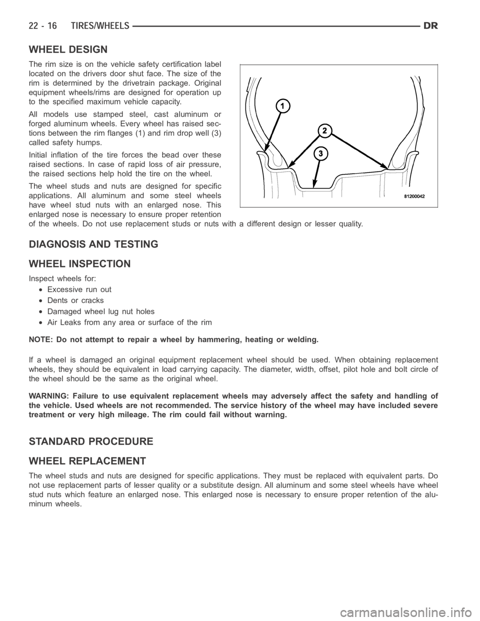
All models use stamped steel, cast aluminum or
forged aluminum wheels. Every wheel has raised sec-
tions between the rim flanges (1) and rim drop well (3)
called safety humps.
Initial inflation of the tire forces the bead over these
raised sections. In case of rapid loss of air pressure,
the raised sections help hold the tire on the wheel.
The wheel studs and nuts are designed for specific
applications. All aluminum and some steel wheels
have wheel stud nuts with an enlarged nose. This
enlarged nose is necessary to ensure proper retention
of the wheels. Do not use replacement studs or nuts with a different design orlesserquality.
DIAGNOSIS AND TESTING
WHEEL INSPECTION
Inspect wheels for:
Excessive run out
Dents or cracks
Damaged wheel lug nut holes
Air Leaks from any area or surface of the rim
NOTE: Do not attempt to repair a wheel by hammering, heating or welding.
If a wheel is damaged an original equipment replacement wheel should be used. When obtaining replacement
wheels, they should be equivalent in load carrying capacity. The diameter, width, offset, pilot hole and bolt circle of
the wheel should be the same as the original wheel.
WARNING: Failure to use equivalent replacement wheels may adversely affect the safety and handling of
the vehicle. Used wheels are not recommended. The service history of the wheel may have included severe
treatment or very high mileage. The rim could fail without warning.
STANDARD PROCEDURE
WHEEL REPLACEMENT
The wheel studs and nuts are designed for specific applications. They mustbe replaced with equivalent parts. Do
not use replacement parts of lesser quality or a substitute design. All aluminum and some steel wheels have wheel
stud nuts which feature an enlarged nose. This enlarged nose is necessary to ensure proper retention of the alu-
minum wheels.
Page 4331 of 5267
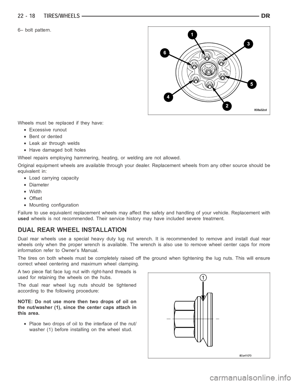
6– bolt pattern.
Wheels must be replaced if they have:
Excessive runout
Bent or dented
Leak air through welds
Have damaged bolt holes
Wheel repairs employing hammering, heating, or welding are not allowed.
Original equipment wheels are available through your dealer. Replacement wheels from any other source should be
equivalent in:
Load carrying capacity
Diameter
Width
Offset
Mounting configuration
Failure to use equivalent replacement wheels may affect the safety and handling of your vehicle. Replacement with
usedwheels is not recommended. Their service history may have included severetreatment.
DUAL REAR WHEELINSTALLATION
Dual rear wheels use a special heavy duty lug nut wrench. It is recommended to remove and install dual rear
wheels only when the proper wrench is available. The wrench is also use to remove wheel center caps for more
information refer to Owner’s Manual.
The tires on both wheels must be completely raised off the ground when tightening the lug nuts. This will ensure
correct wheel centering and maximum wheel clamping.
A two piece flat face lug nut with right-hand threads is
used for retaining the wheels on the hubs.
The dual rear wheel lug nuts should be tightened
according to the following procedure:
NOTE: Do not use more then two drops of oil on
the nut/washer (1), since the center caps attach in
this area.
Place two drops of oil to the interface of the nut/
washer (1) before installing on the wheel stud.
Page 4345 of 5267
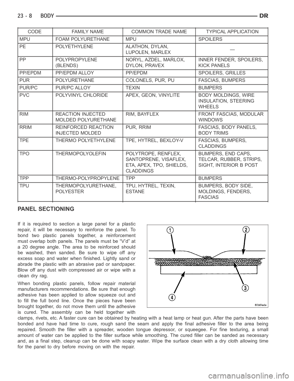
CODE FAMILY NAME COMMON TRADE NAME TYPICAL APPLICATION
MPU FOAM POLYURETHANE MPU SPOILERS
PE POLYETHYLENE ALATHON, DYLAN,
LUPOLEN, MARLEX—
PP POLYPROPYLENE
(BLENDS)NORYL, AZDEL, MARLOX,
DYLON, PRAVEXINNER FENDER, SPOILERS,
KICK PANELS
PP/EPDM PP/EPDM ALLOY PP/EPDM SPOILERS, GRILLES
PUR POLYURETHANE COLONELS, PUR, PU FASCIAS, BUMPERS
PUR/PC PUR/PC ALLOY TEXIN BUMPERS
PVC POLYVINYL CHLORIDE APEX, GEON, VINYLITE BODY MOLDINGS, WIRE
INSULATION, STEERING
WHEELS
RIM REACTION INJECTED
MOLDED POLYURETHANERIM, BAYFLEX FRONT FASCIAS, MODULAR
WINDOWS
RRIM REINFORCED REACTION
INJECTED MOLDEDPUR, RRIM FASCIAS, BODY PANELS,
BODY TRIMS
TPE THERMO POLYETHYLENE TPE, HYTREL, BEXLOY-V FASCIAS, BUMPERS,
CLADDINGS
TPO THERMOPOLYOLEFIN POLYTROPE, RENFLEX,
SANTOPRENE, VISAFLEX,
ETA, APEX, TPO, SHIELDS,
CLADDINGSBUMPERS, END CAPS,
TELCAR, RUBBER, STRIPS,
SIGHT, INTERIOR B POST
TPP THERMO-POLYPROPYLENE TPP BUMPERS
TPU THERMOPOLYURETHANE,
POLYESTERTPU, HYTREL, TEXIN,
ESTANEBUMPERS, BODY SIDE,
MOLDINGS, FENDERS,
FASCIAS
PANEL SECTIONING
If it is required to section a large panel for a plastic
repair, it will be necessary to reinforce the panel. To
bond two plastic panels together, a reinforcement
must overlap both panels. The panels must be “V’d” at
a 20 degree angle. The area to be reinforced should
be washed, then sanded. Be sure to wipe off any
excess soap and water when finished. Lightly sand or
abrade the plastic with an abrasive pad or sandpaper.
Blow off any dust with compressed air or wipe with a
clean dry rag.
When bonding plastic panels, follow repair material
manufacturers recommendations. Be sure that enough
adhesive has been applied to allow squeeze out and
to fill the full bond line. Once the pieces have been
brought together, do not move them until the adhesive
is cured. The assembly can be held together with
clamps, rivets, etc. A faster cure can be obtained by heating with a heat lamp or heat gun. After the parts have been
bonded and have had time to cure, rough sand the seam and apply the final adhesive filler to the area being
repaired. Smooth the filler with a spreader, wooden tongue depressor, or squeegee. For fine texturing, a small
amount of water can be applied to the filler surface while smoothing. The cured filler can be sanded as necessary
and, as a final step, cleanup can be done with soapy water. Wipe the surface clean with a dry cloth allowing time
for the panel to dry before moving on with the repair.
Page 4425 of 5267
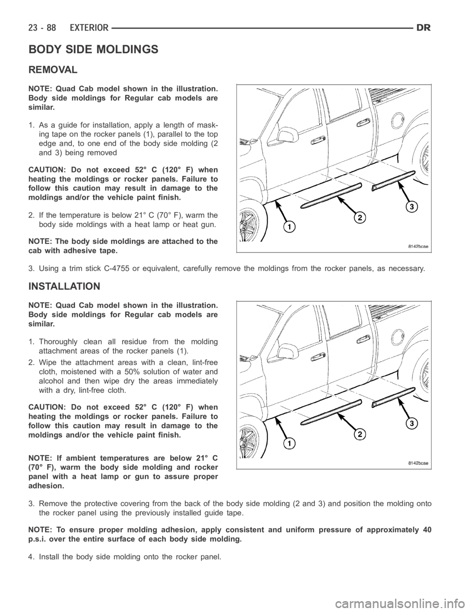
BODY SIDE MOLDINGS
REMOVAL
NOTE: Quad Cab model shown in the illustration.
Body side moldings for Regular cab models are
similar.
1. As a guide for installation, apply a length of mask-
ing tape on the rocker panels (1), parallel to the top
edge and, to one end of the body side molding (2
and 3) being removed
CAUTION: Do not exceed 52° C (120° F) when
heating the moldings or rocker panels. Failure to
follow this caution may result in damage to the
moldings and/or the vehicle paint finish.
2. If the temperature is below 21° C (70° F), warm the
body side moldings with a heat lamp or heat gun.
NOTE: The body side moldings are attached to the
cab with adhesive tape.
3. Using a trim stick C-4755 or equivalent, carefully remove the moldings from the rocker panels, as necessary.
INSTALLATION
NOTE: Quad Cab model shown in the illustration.
Body side moldings for Regular cab models are
similar.
1. Thoroughly clean all residue from the molding
attachment areas of the rocker panels (1).
2. Wipe the attachment areas with a clean, lint-free
cloth, moistened with a 50% solution of water and
alcohol and then wipe dry the areas immediately
with a dry, lint-free cloth.
CAUTION: Do not exceed 52° C (120° F) when
heating the moldings or rocker panels. Failure to
follow this caution may result in damage to the
moldings and/or the vehicle paint finish.
NOTE: If ambient temperatures are below 21° C
(70° F), warm the body side molding and rocker
panel with a heat lamp or gun to assure proper
adhesion.
3. Remove the protective covering from the back of the body side molding (2 and 3) and position the molding onto
the rocker panel using the previously installed guide tape.
NOTE: To ensure proper molding adhesion, apply consistent and uniform pressure of approximately 40
p.s.i. over the entire surface of each body side molding.
4. Install the body side molding onto the rocker panel.
Page 4430 of 5267
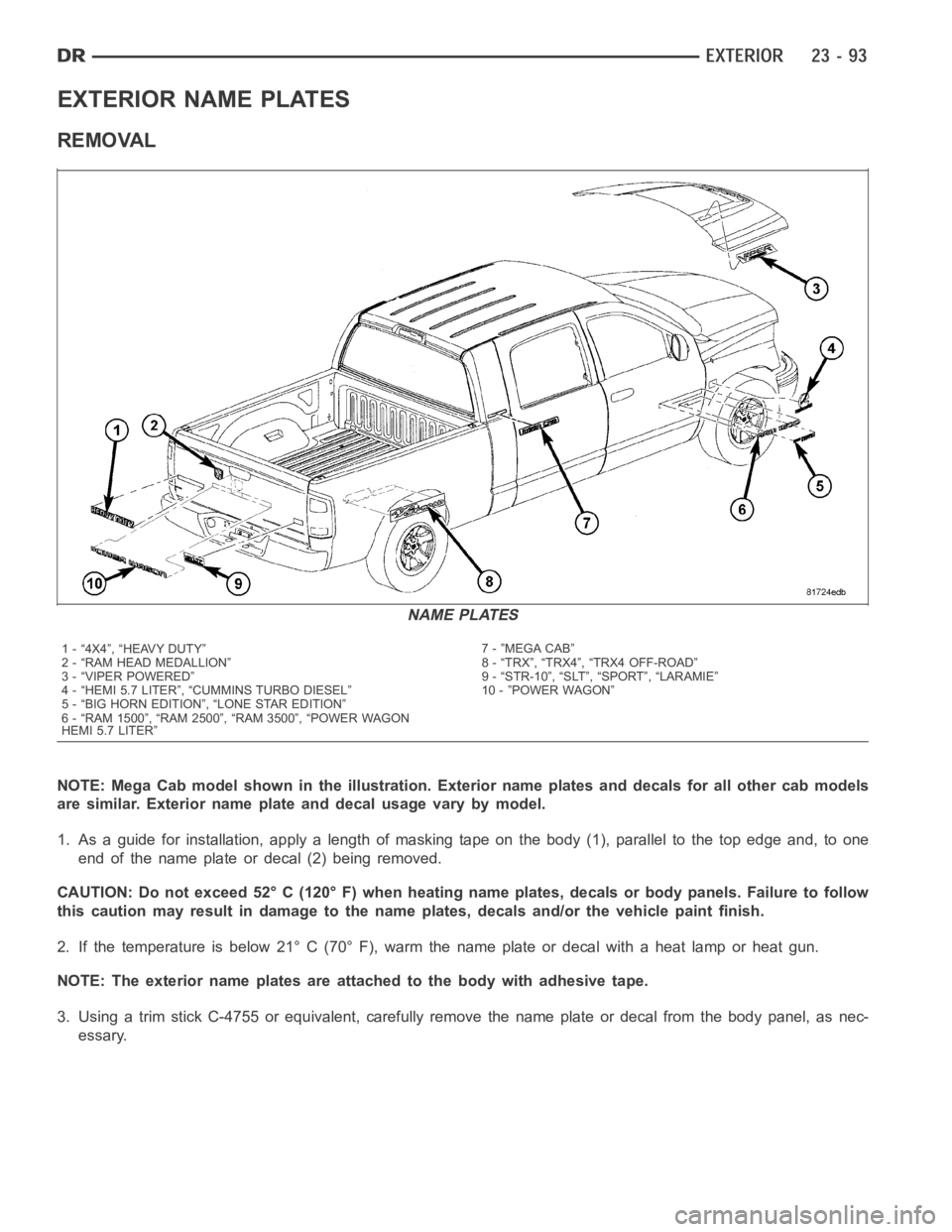
EXTERIOR NAME PLATES
REMOVAL
NOTE: Mega Cab model shown in the illustration. Exterior name plates and decals for all other cab models
are similar. Exterior name plate and decal usage vary by model.
1. As a guide for installation, apply a length of masking tape on the body (1), parallel to the top edge and, to one
end of the name plate or decal (2) being removed.
CAUTION: Do not exceed 52° C (120° F) when heating name plates, decals or body panels. Failure to follow
this caution may result in damage to the name plates, decals and/or the vehicle paint finish.
2. If the temperature is below 21° C (70° F), warm the name plate or decal witha heat lamp or heat gun.
NOTE: The exterior name plates are attached to the body with adhesive tape.
3. Using a trim stick C-4755 or equivalent, carefully remove the name plateor decal from the body panel, as nec-
essary.
NAME PLATES
1 - “4X4”, “HEAVY DUTY”
2 - “RAM HEAD MEDALLION”
3 - “VIPER POWERED”
4 - “HEMI 5.7 LITER”, “CUMMINS TURBO DIESEL”
5 - “BIG HORN EDITION”, “LONE STAR EDITION”
6 - “RAM 1500”, “RAM 2500”, “RAM 3500”, “POWER WAGON
HEMI 5.7 LITER”7 - ”MEGA CAB”
8 - “TRX”, “TRX4”, “TRX4 OFF-ROAD”
9 - “STR-10”, “SLT”, “SPORT”, “LARAMIE”
10 - ”POWER WAGON”
Page 4431 of 5267
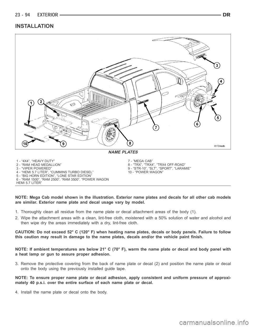
INSTALLATION
NOTE: Mega Cab model shown in the illustration. Exterior name plates and decals for all other cab models
are similar. Exterior name plate and decal usage vary by model.
1. Thoroughly clean all residue from the name plate or decal attachment areas of the body (1).
2. Wipe the attachment areas with a clean, lint-free cloth, moistened witha 50% solution of water and alcohol and
then wipe dry the areas immediately with a dry, lint-free cloth.
CAUTION: Do not exceed 52° C (120° F) when heating name plates, decals or body panels. Failure to follow
this caution may result in damage to the name plates, decals and/or the vehicle paint finish.
NOTE: If ambient temperatures are below 21° C (70° F), warm the name plate ordecal and body panel with
a heat lamp or gun to assure proper adhesion.
3. Remove the protective covering from the back of name plate or decal (2) and position the name plate or decal
onto the body using the previously installed guide tape.
NOTE: To ensure proper name plate or decal adhesion, apply consistent and uniform pressure of approxi-
mately 40 p.s.i. over the entire surface of each name plate or decal.
4. Install the name plate or decal onto the body.
NAME PLATES
1 - “4X4”, “HEAVY DUTY”
2 - “RAM HEAD MEDALLION”
3 - “VIPER POWERED”
4 - “HEMI 5.7 LITER”, “CUMMINS TURBO DIESEL”
5 - “BIG HORN EDITION”, “LONE STAR EDITION”
6 - “RAM 1500”, “RAM 2500”, “RAM 3500”, “POWER WAGON
HEMI 5.7 LITER”7 - ”MEGA CAB”
8 - “TRX”, “TRX4”, “TRX4 OFF-ROAD”
9 - “STR-10”, “SLT”, “SPORT”, “LARAMIE”
10 - ”POWER WAGON”