2006 DODGE RAM SRT-10 heating
[x] Cancel search: heatingPage 5184 of 5267
5.7L ENGINE
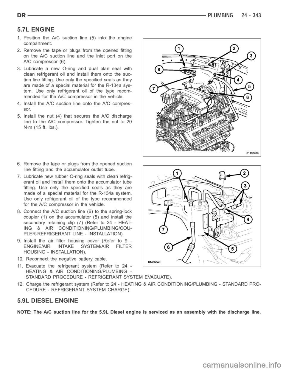
1. Position the A/C suction line (5) into the engine
compartment.
2. Remove the tape or plugs from the opened fitting
on the A/C suction line and the inlet port on the
A/C compressor (6).
3. Lubricate a new O-ring and dual plan seal with
clean refrigerant oil and install them onto the suc-
tion line fitting. Use only the specified seals as they
are made of a special material for the R-134a sys-
tem. Use only refrigerant oil of the type recom-
mended for the A/C compressor in the vehicle.
4. Install the A/C suction line onto the A/C compres-
sor.
5. Install the nut (4) that secures the A/C discharge
line to the A/C compressor. Tighten the nut to 20
Nꞏm (15 ft. lbs.).
6. Remove the tape or plugs from the opened suction
line fitting and the accumulator outlet tube.
7. Lubricate new rubber O-ring seals with clean refrig-
erant oil and install them onto the accumulator tube
fitting. Use only the specified seals as they are
made of a special material for the R-134a system.
Use only refrigerant oil of the type recommended
for the A/C compressor in the vehicle.
8. Connect the A/C suctionline (6) to the spring-lock
coupler (1) on the accumulator (5) and install the
secondary retaining clip (7) (Refer to 24 - HEAT-
ING & AIR CONDITIONING/PLUMBING/COU-
PLER-REFRIGERANT LINE - INSTALLATION).
9. Install the air filter housing cover (Refer to 9 -
ENGINE/AIR INTAKE SYSTEM/AIR FILTER
HOUSING - INSTALLATION).
10. Reconnect the negative battery cable.
11. Evacuate the refrigerant system (Refer to 24 -
HEATING & AIR CONDITIONING/PLUMBING -
STANDARD PROCEDURE - REFRIGERANT SYSTEM EVACUATE).
12. Charge the refrigerant system (Refer to 24 - HEATING & AIR CONDITIONING/PLUMBING - STANDARD PRO-
CEDURE - REFRIGERANT SYSTEM CHARGE).
5.9L DIESEL ENGINE
NOTE: The A/C suction line for the 5.9L Diesel engine is serviced as an assembly with the discharge line.
Page 5185 of 5267
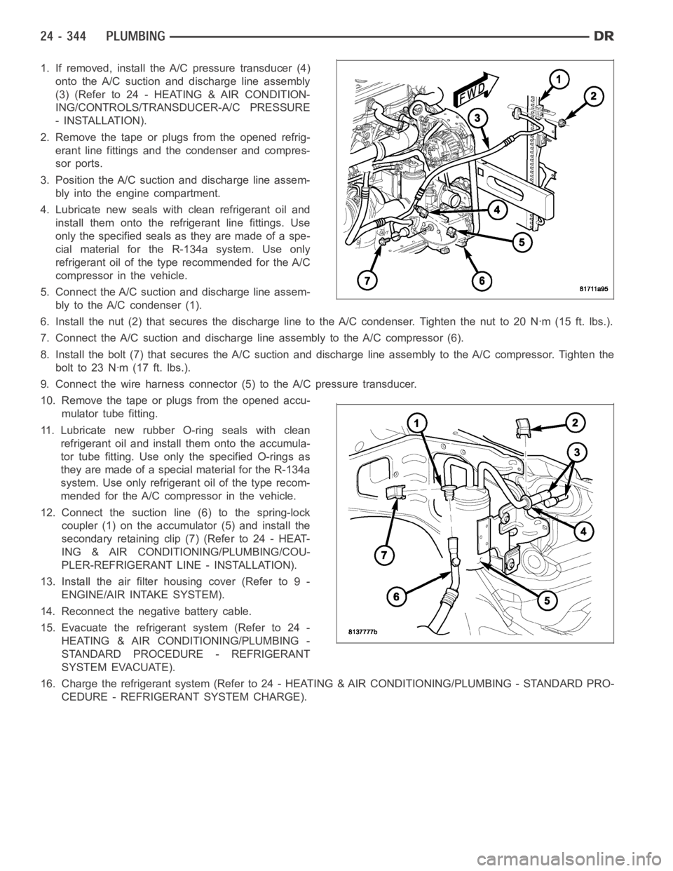
1. If removed, install the A/C pressure transducer (4)
onto the A/C suction and discharge line assembly
(3)(Referto24-HEATING&AIRCONDITION-
ING/CONTROLS/TRANSDUCER-A/C PRESSURE
- INSTALLATION).
2. Remove the tape or plugs from the opened refrig-
erant line fittings and the condenser and compres-
sor ports.
3. Position the A/C suction and discharge line assem-
bly into the engine compartment.
4. Lubricate new seals with clean refrigerant oil and
install them onto the refrigerant line fittings. Use
only the specified seals as they are made of a spe-
cial material for the R-134a system. Use only
refrigerant oil of the type recommended for the A/C
compressor in the vehicle.
5. Connect the A/C suction and discharge line assem-
bly to the A/C condenser (1).
6. Install the nut (2) that secures the discharge line to the A/C condenser.Tighten the nut to 20 Nꞏm (15 ft. lbs.).
7. Connect the A/C suction and discharge line assembly to the A/C compressor(6).
8. Install the bolt (7) that secures the A/C suction and discharge line assembly to the A/C compressor. Tighten the
boltto23Nꞏm(17ft.lbs.).
9. Connect the wire harness connector (5) to the A/C pressure transducer.
10. Remove the tape or plugs from the opened accu-
mulator tube fitting.
11. Lubricate new rubber O-ring seals with clean
refrigerant oil and install them onto the accumula-
tor tube fitting. Use only the specified O-rings as
they are made of a special material for the R-134a
system. Use only refrigerant oil of the type recom-
mended for the A/C compressor in the vehicle.
12. Connect the suction line (6) to the spring-lock
coupler (1) on the accumulator (5) and install the
secondary retaining clip (7) (Refer to 24 - HEAT-
ING & AIR CONDITIONING/PLUMBING/COU-
PLER-REFRIGERANT LINE - INSTALLATION).
13. Install the air filter housing cover (Refer to 9 -
ENGINE/AIR INTAKE SYSTEM).
14. Reconnect the negative battery cable.
15. Evacuate the refrigerant system (Refer to 24 -
HEATING & AIR CONDITIONING/PLUMBING -
STANDARD PROCEDURE - REFRIGERANT
SYSTEM EVACUATE).
16. Charge the refrigerant system (Refer to 24 - HEATING & AIR CONDITIONING/PLUMBING - STANDARD PRO-
CEDURE - REFRIGERANT SYSTEM CHARGE).
Page 5187 of 5267
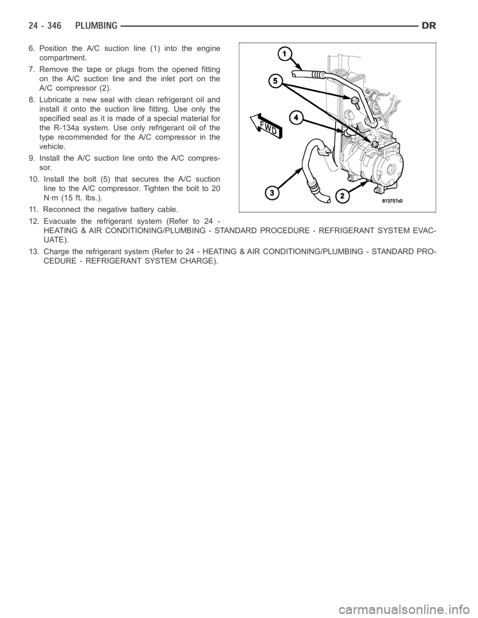
6. Position the A/C suction line (1) into the engine
compartment.
7. Remove the tape or plugs from the opened fitting
on the A/C suction line and the inlet port on the
A/C compressor (2).
8. Lubricate a new seal with clean refrigerant oil and
install it onto the suction line fitting. Use only the
specified seal as it is made of a special material for
the R-134a system. Use only refrigerant oil of the
type recommended for the A/C compressor in the
vehicle.
9. Install the A/C suction line onto the A/C compres-
sor.
10. Install the bolt (5) that secures the A/C suction
line to the A/C compressor. Tighten the bolt to 20
Nꞏm (15 ft. lbs.).
11. Reconnect the negative battery cable.
12. Evacuate the refrigerant system (Refer to 24 -
HEATING & AIR CONDITIONING/PLUMBING - STANDARD PROCEDURE - REFRIGERANT SYSTEM EVAC-
UATE).
13. Charge the refrigerant system (Refer to 24 - HEATING & AIR CONDITIONING/PLUMBING - STANDARD PRO-
CEDURE - REFRIGERANT SYSTEM CHARGE).
Page 5191 of 5267
TUBE-A/C ORIFICE
DESCRIPTION
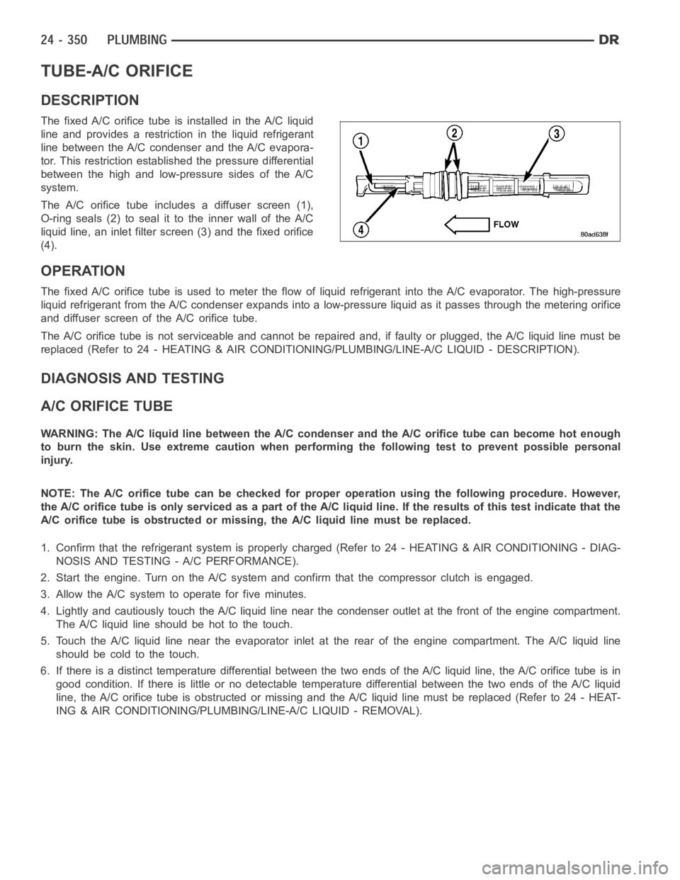
The fixed A/C orifice tube is installed in the A/C liquid
line and provides a restriction in the liquid refrigerant
line between the A/C condenser and the A/C evapora-
tor. This restriction established the pressure differential
between the high and low-pressure sides of the A/C
system.
The A/C orifice tube includes a diffuser screen (1),
O-ring seals (2) to seal it to the inner wall of the A/C
liquid line, an inlet filter screen (3) and the fixed orifice
(4).
OPERATION
The fixed A/C orifice tube is used to meter the flow of liquid refrigerant into the A/C evaporator. The high-pressure
liquid refrigerant from the A/C condenser expands into a low-pressure liquid as it passes through the metering orifice
and diffuser screen of the A/C orifice tube.
The A/C orifice tube is not serviceable and cannot be repaired and, if faulty or plugged, the A/C liquid line must be
replaced (Refer to 24 - HEATING & AIR CONDITIONING/PLUMBING/LINE-A/C LIQUID - DESCRIPTION).
DIAGNOSIS AND TESTING
A/C ORIFICE TUBE
WARNING: The A/C liquid line between the A/C condenser and the A/C orifice tube can become hot enough
to burn the skin. Use extreme caution when performing the following test toprevent possible personal
injury.
NOTE: The A/C orifice tube can be checked for proper operation using the following procedure. However,
the A/C orifice tube is only serviced as a part of the A/C liquid line. If the results of this test indicate that the
A/C orifice tube is obstructed or missing, the A/C liquid line must be replaced.
1. Confirm that the refrigerant system is properly charged (Refer to 24 - HEATING & AIR CONDITIONING - DIAG-
NOSIS AND TESTING - A/C PERFORMANCE).
2. Start the engine. Turn on the A/Csystem and confirm that the compressor clutch is engaged.
3. Allow the A/C system to operate for five minutes.
4. Lightly and cautiously touch the A/C liquid line near the condenser outlet at the front of the engine compartment.
TheA/Cliquidlineshouldbehottothetouch.
5. Touch the A/C liquid line near the evaporator inlet at the rear of the engine compartment. The A/C liquid line
should be cold to the touch.
6. If there is a distinct temperature differential between the two ends of the A/C liquid line, the A/C orifice tube is in
good condition. If there is little or no detectable temperature differential between the two ends of the A/C liquid
line, the A/C orifice tube is obstructed or missing and the A/C liquid line must be replaced (Refer to 24 - HEAT-
ING & AIR CONDITIONING/PLUMBING/LINE-A/C LIQUID - REMOVAL).
Page 5194 of 5267
The following is a list of the system monitors:
Misfire Monitor
Fuel System Monitor
Oxygen Sensor Monitor
Oxygen Sensor Heater Monitor
Catalyst Monitor
Leak Detection Pump Monitor (if equipped)
All these system monitors require two consecutive trips with the malfunction present to set a fault.
Refer to the appropriate Powertrain Diagnostics Procedures manual for diagnostic procedures.
The following is an operation and description of each system monitor:
OXYGEN SENSOR (O2S) MONITOR
Effective control of exhaust emissions is achieved by an oxygen feedback system. The most important element of
the feedback system is the O2S. The O2S is located in the exhaust path. Once it reaches operating temperature
300° to 350°C (572° to 662°F), the sensor generates a voltage that is inversely proportional to the amount of oxy-
gen in the exhaust. The information obtained by the sensor is used to calculate the fuel injector pulse width. This
maintains a 14.7 to 1 Air Fuel (A/F) ratio. At this mixture ratio, the catalyst works best to remove hydrocarbons (HC),
carbon monoxide (CO) and nitrogen oxide (NOx) from the exhaust.
The O2S is also the main sensing element for the Catalyst and Fuel Monitors.
The O2S can fail in any or all of the following manners:
slow response rate
reduced output voltage
dynamic shift
shortedoropencircuits
Response rate is the time required for the sensor to switch from lean to richonce it is exposed to a richer than
optimum A/F mixture or vice versa. As the sensor starts malfunctioning, itcould take longer to detect the changes
in the oxygen content of the exhaust gas.
The output voltage of the O2S ranges from 0 to 1 volt. A good sensor can easilygenerate any output voltage in this
range as it is exposed to different concentrations of oxygen. To detect a shift in the A/F mixture (lean or rich), the
output voltage has to change beyond a threshold value. A malfunctioning sensor could have difficulty changing
beyond the threshold value.
OXYGEN SENSOR HEATER MONITOR
If there is an oxygen sensor (O2S) shorted to voltage DTC, as well as a O2S heater DTC, the O2S fault MUST be
repaired first. Before checking the O2S fault, verify that the heater circuit is operating correctly.
Effective control of exhaust emissions is achieved by an oxygen feedback system. The most important element of
the feedback system is the O2S. The O2S is located in the exhaust path. Once it reaches operating temperature
300°C to 350°C (572°F to 662°F), the sensor generates a voltage that is inversely proportional to the amount of
oxygen in the exhaust. The information obtained by the sensor is used to calculate the fuel injector pulse width. This
maintains a 14.7 to 1 Air Fuel (A/F) ratio. At this mixture ratio, the catalyst works best to remove hydrocarbons (HC),
carbon monoxide (CO) and nitrogen oxide (NOx) from the exhaust.
The voltage readings taken from the O2S sensor are very temperature sensitive. The readings are not accurate
below 572°F (300°C). Heating of the O2S sensor is done to allow the engine controllertoshifttoclosedloopcontrol
as soon as possible. The heating element used to heat the O2S sensor must be testedtoensurethatitisheating
the sensor properly.
The O2S sensor circuit is monitored for a drop in voltage. The sensor outputis used to test the heater by isolating
the effect of the heater element on the O2S sensor output voltage from the other effects.
LEAK DETECTION PUMP MONITOR (IF EQUIPPED)
The leak detection assembly incorporates two primary functions: it must detect a leak in the evaporative system and
seal the evaporative system so the leak detection test can be run.