Page 3458 of 5267
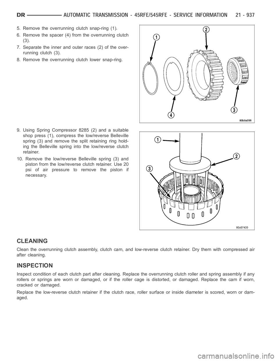
5. Remove the overrunning clutch snap-ring (1).
6. Remove the spacer (4) from the overrunning clutch
(3).
7. Separate the inner and outer races (2) of the over-
running clutch (3).
8. Remove the overrunning clutch lower snap-ring.
9. Using Spring Compressor 8285 (2) and a suitable
shop press (1), compress the low/reverse Belleville
spring (3) and remove the split retaining ring hold-
ing the Belleville spring into the low/reverse clutch
retainer.
10. Remove the low/reverse Belleville spring (3) and
piston from the low/reverse clutch retainer. Use 20
psi of air pressure to remove the piston if
necessary.
CLEANING
Cleantheoverrunningclutchassembly,clutchcam,andlow-reverseclutch retainer. Dry them with compressed air
after cleaning.
INSPECTION
Inspect condition of each clutch part after cleaning. Replace the overrunning clutch roller and spring assembly if any
rollers or springs are worn or damaged, or if the roller cage is distorted, or damaged. Replace the cam if worn,
cracked or damaged.
Replace the low-reverse clutch retainer if the clutch race, roller surface or inside diameter is scored, worn or dam-
aged.
Page 3459 of 5267
ASSEMBLY
1. Check the bleed orifice to ensure that it is not
plugged or restricted.
2. Install a new seal on the low/reverse piston. Lubri-
cate the seal with Mopar
ATF +4, Automatic
Transmission Fluid, prior to installation.
3. Install the low/reverse piston into the low/reverse
clutch retainer.
4. Position the low/reverse Belleville spring (3) on the
low/reverse piston.
5. Using Spring Compressor 8285 (2) and a suitable
shop press (1), compress the low/reverse Belleville
spring (3) and install the split retaining ring to hold
the Belleville spring into the low/reverse clutch
retainer.
6. Install the lower overrunning clutch snap-ring.
7. Assemble the inner and outer races (2) of the over-
running clutch (3).
8. Position the overrunning clutch spacer (4) on the
overrunning clutch (3).
9. Install the upper overrunning clutch snap-ring (1).
Page 3460 of 5267
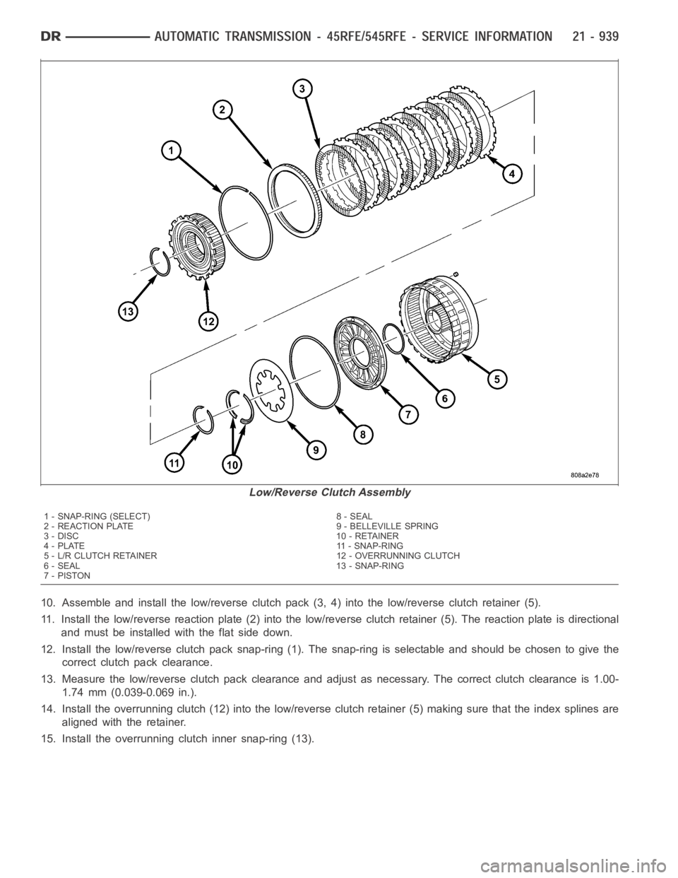
10. Assemble and install the low/reverse clutch pack (3, 4) into the low/reverse clutch retainer (5).
11. Install the low/reverse reaction plate (2) into the low/reverse clutch retainer (5). The reaction plate is directional
and must be installed with the flat side down.
12. Install the low/reverse clutch pack snap-ring (1). The snap-ring is selectable and should be chosen to give the
correct clutch pack clearance.
13. Measure the low/reverse clutch pack clearance and adjust as necessary. The correct clutch clearance is 1.00-
1.74 mm (0.039-0.069 in.).
14. Install the overrunning clutch (12) into the low/reverse clutch retainer (5) making sure that the index splines are
aligned with the retainer.
15. Install the overrunning clutch inner snap-ring (13).
Low/Reverse Clutch Assembly
1 - SNAP-RING (SELECT) 8 - SEAL
2 - REACTION PLATE 9 - BELLEVILLE SPRING
3 - DISC 10 - RETAINER
4 - PLATE 11 - SNAP-RING
5 - L/R CLUTCH RETAINER 12 - OVERRUNNING CLUTCH
6 - SEAL 13 - SNAP-RING
7-PISTON
Page 3462 of 5267
The oil pump also contains a number of valves. The
converter clutch switch (3) and control valves (2),
pressure regulator valve (5), and converter pressure
limit valve (6) are all located in the oil pump valve
body.
A front seal (2), and a bolt on reaction shaft (5) complete the oil pump assembly.
Oil Pump Reaction Shaft
1 - PUMP HOUSING 4 - SEAL RING (5)
2 - SEAL 5 - REACTION SHAFT SUPPORT
3 - OIL FILTER SEAL 6 - PUMP VALVE BODY
Page 3463 of 5267
OPERATION
As the torque converter rotates, the converter hub rotates the oil pump drive gear. As the drive gear rotates both
driven gears, a vacuum is created when the gear teeth come out of mesh. This suction draws fluid through the
pump inlet from the oil pan. As the gear teeth come back into mesh, pressurized fluid is forced into the pump outlet
and to the oil pump valves.
At low speeds, both sides of the pump supply fluid to the transmission. As the speed of the torque converter
increases, the flow from both sides increases until the flow from the primary side alone is sufficient to meet system
demands. At this point, the check valve located between the two pumps closes. The secondary side is shut down
and the primary side supplies all the fluid to the transmission.
CONVERTER CLUTCH SWITCH VALVE
The converter clutch switch valve is used to control the hydraulic pressure supplied to the front (OFF) side of the
torque converter clutch.
CONVERTER CLUTCH REGULATOR VALVE
The converter clutch regulator valve is used to control the hydraulic pressure supplied to the back (ON) side of the
torque converter clutch.
TORQUE CONVERTER LIMIT VALVE
The torque converter limit valve serves to limit the available line pressure to the torque converter clutch.
STANDARD PROCEDURE - OIL PUMP VOLUME CHECK
Measuring the oil pump output volume will determine if sufficient oil flowto the transmission oil cooler exists, and
whether or not an internal transmission failure is present.
Verify that the transmission fluid is at the proper level. Refer to the Fluid Level Check procedure in this section. If
necessary, fill the transmission to the proper level with Mopar
ATF +4, Automatic Transmission Fluid.
1. Disconnect theTo coolerline at the cooler inlet and place a collecting container under the disconnected line.
CAUTION: With the fluid set at the proper level, fluid collection should not exceed (1) quart or internal dam-
age to the transmission may occur.
2. Run the engineat 1800 rpm, with the shift selector in neutral. Verify that the transmission fluid temperature is
below 104.5° C (220° F) for this test.
3. If one quart of transmission fluid is collected in the container in 30 seconds or less, oil pump flow volume is
within acceptable limits. If fluid flow is intermittent, or it takes more than 30 seconds to collect one quart of fluid,
refer to the Hydraulic Pressure tests in this section for further diagnosis.
4. Re-connect theTo c o o l e rline to the transmission cooler inlet.
5. Refill the transmission to proper level.
Page 3472 of 5267
SENSOR-OUTPUT SPEED
DESCRIPTION
The Input and Output Speed Sensors are two-wire magnetic pickup devices that generate AC signals as rotation
occurs. They are mounted in the left side of the transmission case and are considered primary inputs to the Trans-
mission Control Module (TCM).
OPERATION
The Input Speed Sensor provides information on how fast the input shaft is rotating. As the teeth of the input clutch
hub pass by the sensor coil, an AC voltage is generated and sent to the TCM. The TCM interprets this information
as input shaft rpm.
The Output Speed Sensor generates an AC signal in a similar fashion, thoughitscoilisexcitedbyrotationofthe
rear planetary carrier lugs. The TCM interprets this information as outputshaftrpm.
The TCM compares the input and output speed signals to determine the following:
Transmission gear ratio
Speed ratio error detection
CVI calculation
The TCM also compares the input speed signal and the engine speed signal to determine the following:
Torque converter clutch slippage
Torque converter element speed ratio
REMOVAL
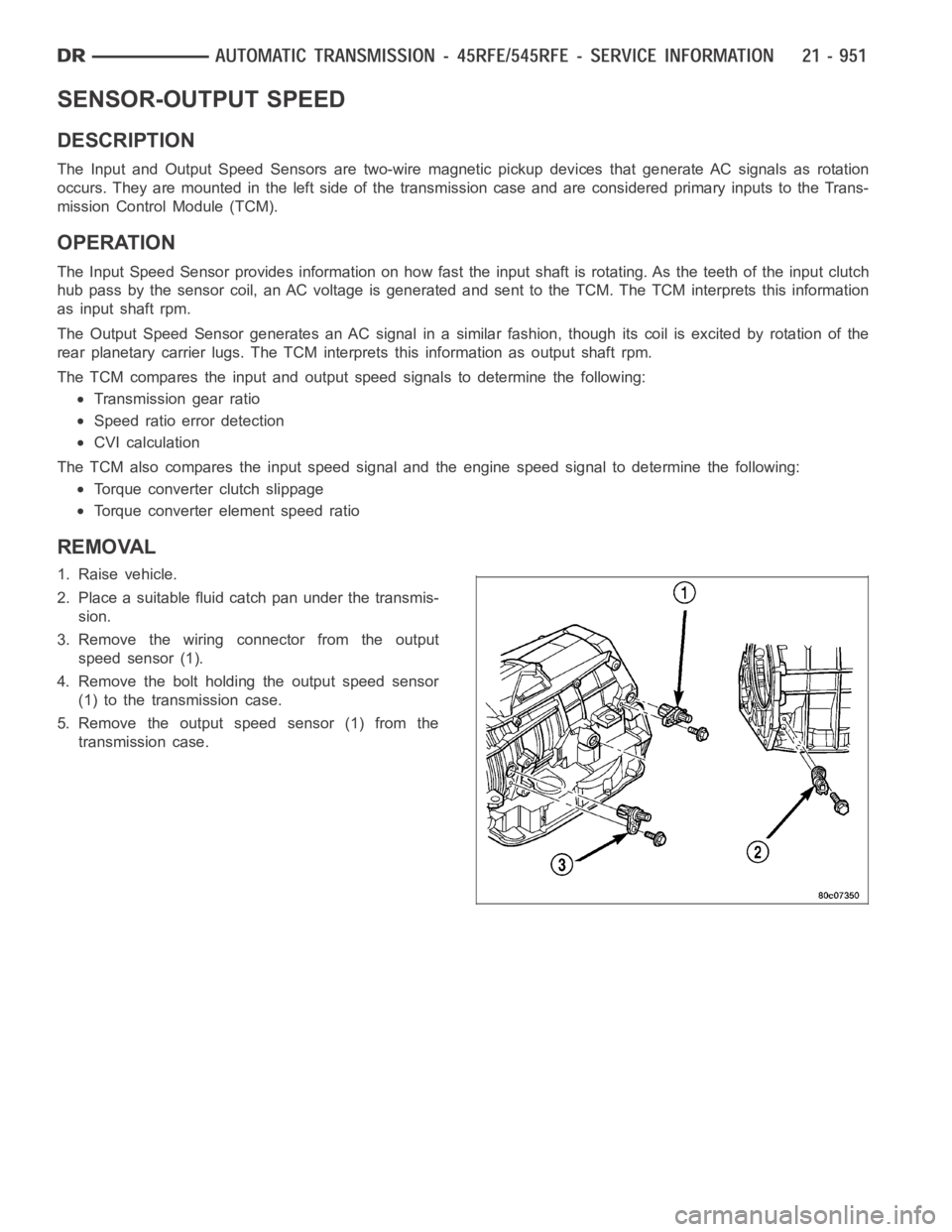
1. Raise vehicle.
2. Place a suitable fluid catch pan under the transmis-
sion.
3. Remove the wiring connector from the output
speed sensor (1).
4. Remove the bolt holding the output speed sensor
(1) to the transmission case.
5. Remove the output speed sensor (1) from the
transmission case.
Page 3477 of 5267
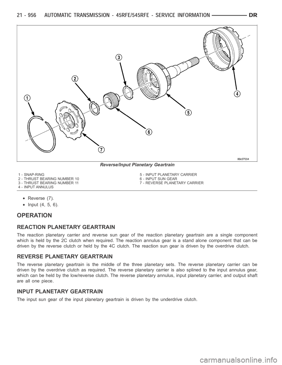
Reverse (7).
Input (4, 5, 6).
OPERATION
REACTION PLANETARY GEARTRAIN
The reaction planetary carrier and reverse sun gear of the reaction planetary geartrain are a single component
which is held by the 2C clutch when required. The reaction annulus gear is a stand alone component that can be
driven by the reverse clutch or held by the 4C clutch. The reaction sun gear is driven by the overdrive clutch.
REVERSE PLANETARY GEARTRAIN
The reverse planetary geartrain is the middle of the three planetary sets.The reverse planetary carrier can be
driven by the overdrive clutch as required. The reverse planetary carrieris also splined to the input annulus gear,
which can be held by the low/reverse clutch. The reverse planetary annulus, input planetary carrier, and output shaft
areallonepiece.
INPUT PLANETARY GEARTRAIN
The input sun gear of the input planetary geartrain is driven by the underdrive clutch.
Reverse/Input Planetary Geartrain
1 - SNAP-RING 5 - INPUT PLANETARY CARRIER
2 - THRUST BEARING NUMBER 10 6 - INPUT SUN GEAR
3 - THRUST BEARING NUMBER 11 7 - REVERSE PLANETARY CARRIER
4 - INPUT ANNULUS
Page 3481 of 5267
VALVE-SOLENOID SWITCH
DESCRIPTION
The Solenoid Switch Valve (SSV) is located in the valve body and controls the direction of the transmission fluid
when the L/R-TCC solenoid is energized.
OPERATION
The Solenoid Switch Valve controls line pressure from the LR-TCC solenoid. In 1st gear, the SSV will be in the
downshifted position, thus directing fluid to the L/R clutch circuit. In 2nd, 3rd, 4th, and 5th (if applicable) gears, the
solenoid switch valve will be in the upshifted position and directs the fluid into the torque converter clutch (TCC)
circuit.
When shifting into 1st gear, a special hydraulic sequence is performed to ensure SSV movement into the down-
shifted position. The L/R pressure switch is monitored to confirm SSV movement. If the movement is not confirmed
(the L/R pressure switch does not close), 2nd gear is substituted for 1st. ADTC will be set after three unsuccessful
attempts are made to get into 1st gear in one given key start.