Page 3385 of 5267
19. Install the number 12 thrust bearing (3) over the
output shaft and against the rear planetary gear
set. The flat side of the bearing goes toward the
planetary gearset and the raised tabs on the inner
race should face the rear of the transmission.
20. Install the reverse/input planetary assembly (1)
through the low/reverse clutch assembly.
21. Install the park sprag gear (1) onto the output
shaft.
22. Install the snap-ring (1) to hold the park sprag
onto the output shaft.
Page 3386 of 5267
23. Install the 2C reaction plate (4) into the transmis-
sion case.
24. Install the 2C clutch pack (2, 3, 4) into the trans-
mission case.
25. Install the number 8 thrust bearing (1) inside the reaction carrier with the outer race against the reaction plan-
etary carrier (3).
26. Install the reaction planetary gear set and the number 9 thrust bearing(2), with the inner race against the reac-
tion planetary carrier (3), into the transmission case.
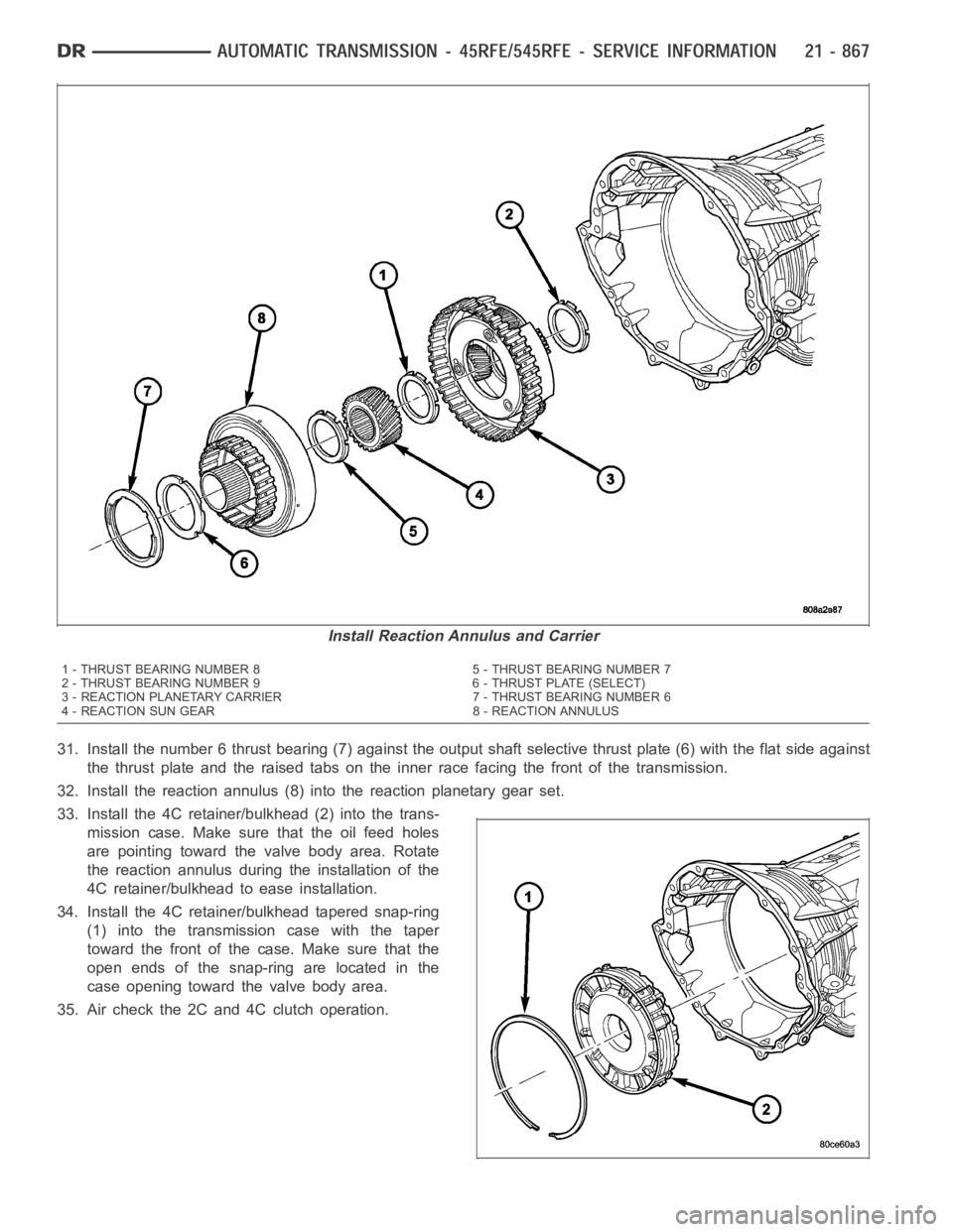
Install Reaction Annulus and Carrier
1 - THRUST BEARING NUMBER 8 5 - THRUST BEARING NUMBER 7
2 - THRUST BEARING NUMBER 9 6 - THRUST PLATE (SELECT)
3 - REACTION PLANETARY CARRIER 7 - THRUST BEARING NUMBER 6
4 - REACTION SUN GEAR 8 - REACTION ANNULUS
Page 3387 of 5267
27. Install the flat 2C clutch snap-ring into the transmission case.
28. Install the reaction sun gear (4) into the reaction planetary gear set.Make surethe small shoulder is facing the
front of the transmission.
29. Install the number 7 thrust bearing (5) onto the reaction sun gear (4) with the inner race against the sun gear.
30. Install the output shaft selective thrust plate (2)
onto the reaction annulus with the oil grooves fac-
ing the annulus gear and the lugs (1) and notches
aligned as shown.
Page 3388 of 5267

31. Install the number 6 thrust bearing (7) against the output shaft selective thrust plate (6) with the flat side against
the thrust plate and the raised tabs on the inner race facing the front of thetransmission.
32. Install the reaction annulus (8) into the reaction planetary gear set.
33. Install the 4C retainer/bulkhead (2) into the trans-
mission case. Make sure that the oil feed holes
are pointing toward the valve body area. Rotate
the reaction annulus during the installation of the
4C retainer/bulkhead to ease installation.
34. Install the 4C retainer/bulkhead tapered snap-ring
(1) into the transmission case with the taper
toward the front of the case. Make sure that the
open ends of the snap-ring are located in the
case opening toward the valve body area.
35. Air check the 2C and 4C clutch operation.
Install Reaction Annulus and Carrier
1 - THRUST BEARING NUMBER 8 5 - THRUST BEARING NUMBER 7
2 - THRUST BEARING NUMBER 9 6 - THRUST PLATE (SELECT)
3 - REACTION PLANETARY CARRIER 7 - THRUST BEARING NUMBER 6
4 - REACTION SUN GEAR 8 - REACTION ANNULUS
Page 3389 of 5267

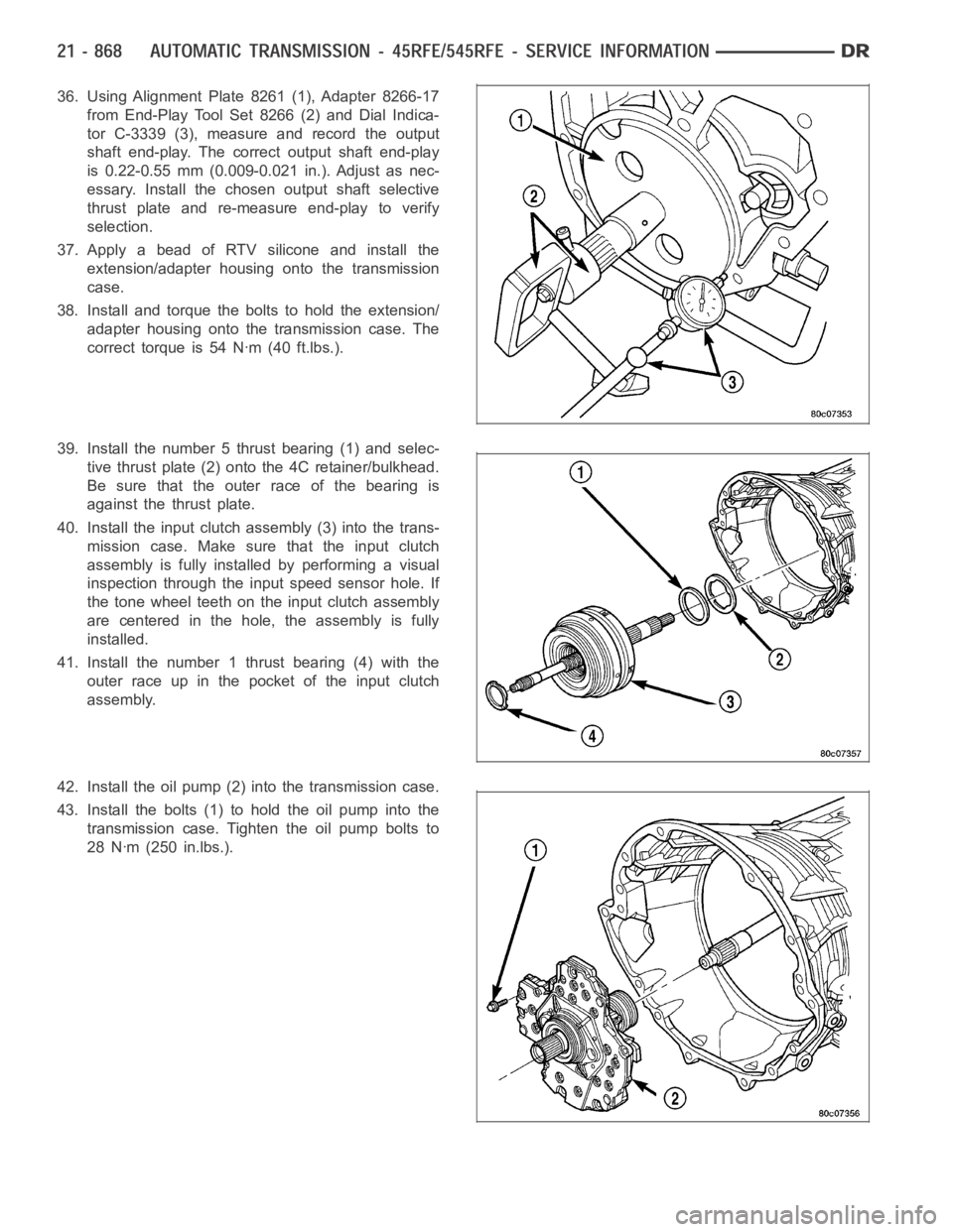
36. Using Alignment Plate 8261 (1), Adapter 8266-17
from End-Play Tool Set 8266 (2) and Dial Indica-
tor C-3339 (3), measure and record the output
shaft end-play. The correct output shaft end-play
is 0.22-0.55 mm (0.009-0.021 in.). Adjust as nec-
essary. Install the chosen output shaft selective
thrust plate and re-measure end-play to verify
selection.
37. Apply a bead of RTV silicone and install the
extension/adapter housing onto the transmission
case.
38. Install and torque the bolts to hold the extension/
adapter housing onto the transmission case. The
correct torque is 54 Nꞏm (40 ft.lbs.).
39. Install the number 5 thrust bearing (1) and selec-
tive thrust plate (2) onto the 4C retainer/bulkhead.
Be sure that the outer race of the bearing is
against the thrust plate.
40. Install the input clutch assembly (3) into the trans-
mission case. Make sure that the input clutch
assembly is fully installedbyperformingavisual
inspection through the input speed sensor hole. If
the tone wheel teeth on the input clutch assembly
are centered in the hole, the assembly is fully
installed.
41. Install the number 1 thrust bearing (4) with the
outer race up in the pocket of the input clutch
assembly.
42. Install the oil pump (2) into the transmission case.
43. Install the bolts (1) to hold the oil pump into the
transmission case. Tighten the oil pump bolts to
28 Nꞏm (250 in.lbs.).
Page 3390 of 5267

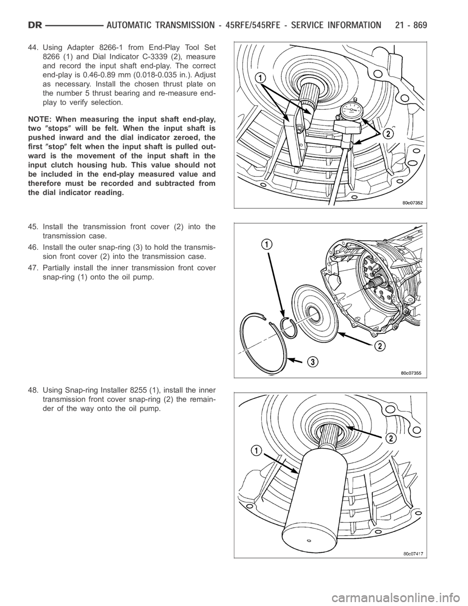
44. Using Adapter 8266-1 from End-Play Tool Set
8266 (1) and Dial Indicator C-3339 (2), measure
and record the input shaft end-play. The correct
end-play is 0.46-0.89 mm (0.018-0.035 in.). Adjust
as necessary. Install the chosen thrust plate on
the number 5 thrust bearing and re-measure end-
play to verify selection.
NOTE: When measuring the input shaft end-play,
two
stopswill be felt. When the input shaft is
pushed inward and the dial indicator zeroed, the
first
stopfelt when the input shaft is pulled out-
wardisthemovementoftheinputshaftinthe
input clutch housing hub. This value should not
be included in the end-play measured value and
therefore must be recorded and subtracted from
the dial indicator reading.
45. Install the transmission front cover (2) into the
transmission case.
46. Install the outer snap-ring (3) to hold the transmis-
sion front cover (2) into the transmission case.
47. Partially install the inner transmission front cover
snap-ring (1) onto the oil pump.
48. Using Snap-ring Installer 8255 (1), install the inner
transmission front cover snap-ring (2) the remain-
der of the way onto the oil pump.
Page 3394 of 5267
CAUTION: It is essential that correct length bolts
be used to attach the converter to the driveplate.
Bolts that are too long will damage the clutch sur-
face inside the converter.
25. Install torque converter-to-driveplate bolts. Tighten
boltsto31Nꞏm(270in.lbs.).
26. Install starter motor and cooler line bracket.
27. Connect cooler lines to transmission.
28. Install transmission fill tube.
29. Install exhaust components, if necessary.
30. Install the structural dust cover (2) (Refer to 9 -
ENGINE/ENGINE BLOCK/STRUCTURAL COVER
- INSTALLATION) onto the transmission and the
engine.
31. Align and connect propeller shaft(s).
32. Adjust gearshift cable if necessary.
33. Install any skid plates removed previously. (Refer
to 13 - FRAMES & BUMPERS/FRAME/TRANS-
FER CASE SKID PLATE - INSTALLATION)
34. Lower vehicle.
35. Fill transmission with Mopar
ATF +4, Automatic Transmission Fluid.
Page 3417 of 5267

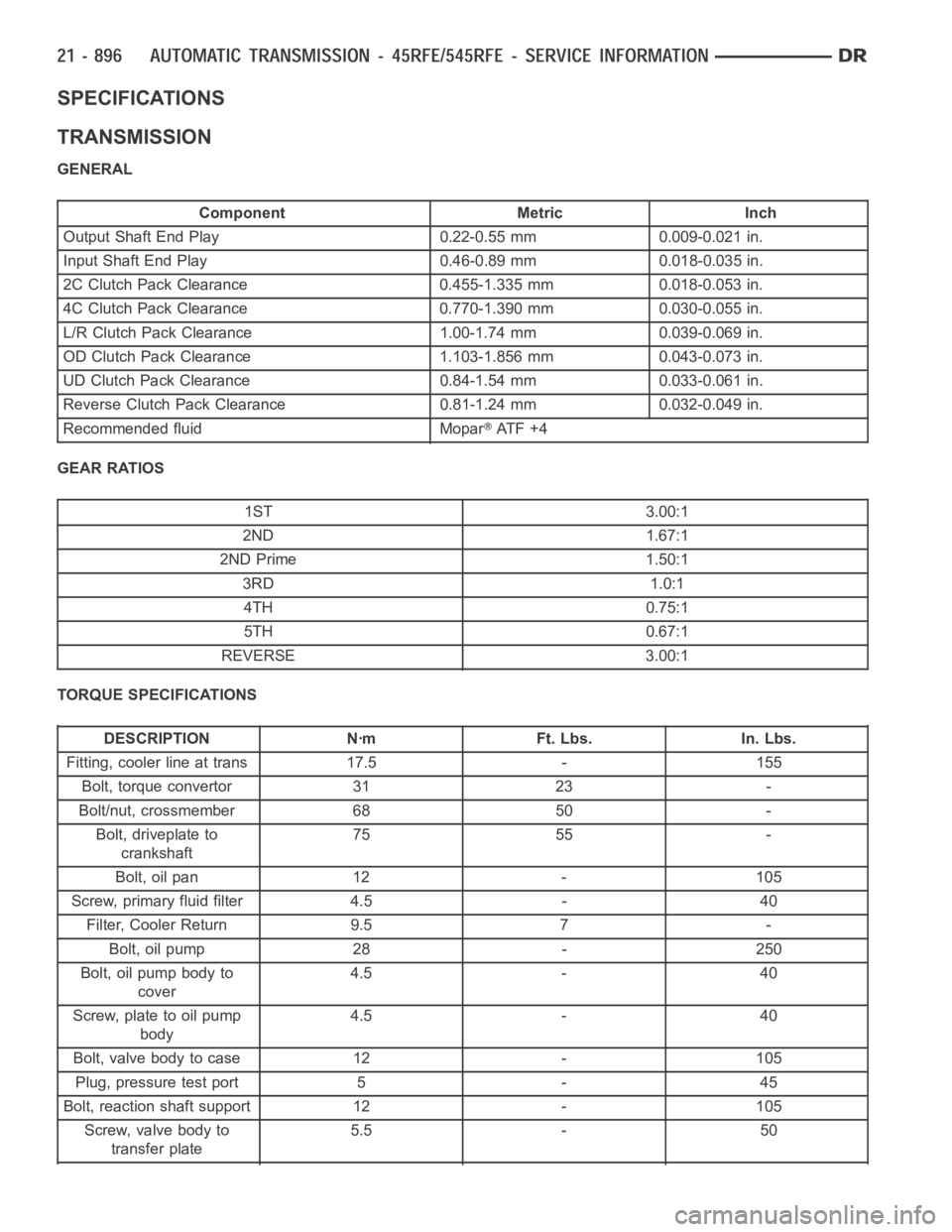
SPECIFICATIONS
TRANSMISSION
GENERAL
Component Metric Inch
Output Shaft End Play 0.22-0.55 mm 0.009-0.021 in.
Input Shaft End Play 0.46-0.89 mm 0.018-0.035 in.
2C Clutch Pack Clearance 0.455-1.335 mm 0.018-0.053 in.
4C Clutch Pack Clearance 0.770-1.390 mm 0.030-0.055 in.
L/R Clutch Pack Clearance 1.00-1.74 mm 0.039-0.069 in.
OD Clutch Pack Clearance 1.103-1.856 mm 0.043-0.073 in.
UD Clutch Pack Clearance 0.84-1.54 mm 0.033-0.061 in.
Reverse Clutch Pack Clearance 0.81-1.24 mm 0.032-0.049 in.
Recommended fluid Mopar
AT F + 4
GEAR RATIOS
1ST 3.00:1
2ND 1.67:1
2ND Prime 1.50:1
3RD 1.0:1
4TH 0.75:1
5TH 0.67:1
REVERSE 3.00:1
TORQUE SPECIFICATIONS
DESCRIPTION Nꞏm Ft. Lbs. In. Lbs.
Fitting, cooler line at trans 17.5 - 155
Bolt, torque convertor 31 23 -
Bolt/nut, crossmember 68 50 -
Bolt, driveplate to
crankshaft75 55 -
Bolt, oil pan 12 - 105
Screw, primary fluid filter 4.5 - 40
Filter, Cooler Return 9.5 7 -
Bolt, oil pump 28 - 250
Bolt, oil pump body to
cover4.5 - 40
Screw, plate to oil pump
body4.5 - 40
Bolt, valve body to case 12 - 105
Plug, pressure test port 5 - 45
Bolt, reaction shaft support 12 - 105
Screw, valve body to
transfer plate5.5 - 50